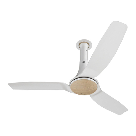
Nex Glyde A50 User manual

Have more questions? Talk to us at care@nexlife.com
This handy guide will help you
put your Nex fan together.
INSTRUCTION
MANUAL

Note:- Kindly use same serial number blade as these are precisely balanced for same weight.Note:- Kindly use same serial number blade as these are precisely balanced for same weight.
1. Place the motor on thermo buffer to avoid any scratches as shown in (Figure 1).
2. Unscrew the blade screw from Motor and align the blade with the motor as
shown in (Figure 1).
3. Screw the Blade to the Motor and ensure a tight fit.
Figure 1 Figure 2
Figure 5Figure 4Figure 3
Classification | Internal
CONNECTION
WIRES
CANOPY STOPPER
DOWN ROD
6
7
9
11
10
8
MOTOR
CONNECTION
WIRES
BOTTOM CANOPY
THERMO BUFFER
BLADE FIXING SCREW
BLADE
MOTOR

1. Hold the down-rod vertically with Slit side downward.
2. Pass the connection wires through slit hole at the Bottom end of
down rod (3) and remove them from the top end of down rod
(Figure 2). Slide canopy stopper (4a) from bottom side & ensure
connection wire will be aligned with stopper slot (Figure 6a).
3. Insert the bottom end of down rod (3) (with slit) on spindle (6)
and insert bolt (7) Place the plain washer (8), spring washer (9),
and fully tighten nut (10), insert the split pin (11) in the small
hole on the bolt end and open the ends, so that it does not fall
off. The assembly of bolt (7), plain washer (8), spring washer
(9), nut (10), split pin (11) is separately packed with hanger
assembly (18).
4. Align hole in downrod (3) and slot in canopy stopper(4a) and
push canopy stopper (4a) from top to rest it on bolt (3) &
connect connection wire to the terminal block. (Figure 3).
5. Slide the bottom canopy (4) from top end of down rod (3) and
rest it on canopy stopper (4a) (Figure 4).
6. Slide the top Canopy(5) in Bottom canopy (4) and push it
downward. (Figure 5)
7. Slide the false ceiling cover (5b) from top end of down rod (3)
and rest it on top canopy (5) (Figure 5).
8. Remove the split pin (17), nut (16), spring washer (15), plain
washer (14), bolt (13), at the bottom end of hanger assembly
(12).(Figure 6)
9. Place hanger assembly (12) in ceiling hook in such a way that
rubber reel (18) rests on the ceiling hook.
10. Insert the top end of down rod (3) between the steel clamps of
hanger assembly (12). Match the holes with holes in down rod
(3). Insert bolt (13), place plain washer (14), spring washer (15),
and fully tighten nut (16), insert the split pin (17) in the small hole
on bolt end and open the ends, so that it does not fall off.
11. Assemble top canopy (5) and false ceiling cover (5b) together
and lift the Top canopy (5) and false ceiling cover (5b) to cover
hanger assembly and fix with screw (5a) (Figure 6).
12. Connect the regulator (not supplied along with fan) in the series
with fan.
Figure 6
Figure 6 a
Classification | Internal
CONNECTION
WIRES
TERMINAL
BLOCK
16
14
17
15
12
13
TOP END OF
DOWN ROD
6
7
9
11
10
8
1
2
7a
BOTTOM END OF
DOWN ROD
WITH SLIT
MOTOR
BODY
THERMO BUFFER
18
4
5
3
SCREW
5a
Canopy stopper
4a
5b
CONNECTION
WIRES
CANOPY
STOPPER

1. Assemble top canopy (5) and false ceiling cover (5b) togather (figure 7) and slide it up
from bottom end of down rod (already mounted).
2. Slide the bottom canopy(4) from down side of top canopy(5).
3. Slide canopy stopper (4a) from bottom end of down rod (already mounted) (Figure 7).
4. Insert the bottom end of down rod (already mounted) (with slit) on spindle (6) and insert
bolt (7) Place the plain washer (8), spring washer (9), and fully tighten nut (10), insert
the split pin (11) in the small hole on the bolt end and open the ends, so that it does not
fall off. The assembly of bolt (7), plain washer (8), spring washer (9), nut(10) split pin
(11) is separately packed with hanger assembly (12). & connect connection wire with
terminal block.
5. Push canopy stopper (4a) from top to rest it on bolt (7) (Figure 7). Slide down bottom
canopy and rest it on canopy stopper.
6. Lift the Top Canopy (5) and false ceiling cover (5b) assembly as per requirement to cover
false ceiling hole and Tighten the screw (5a) to fix it (Figure 6).
Figure 8Figure 7
Note:- If there, is not sufficient
space to accommodate top
canopy (5), kindly cut the top
canopy (5) from top side /
Bottom Side (Figure 8),
assemble false ceiling cover
(5b) in Top canopy (5), and
assemble as per instruction
(Figure 8).
Classification | Internal
TERMINAL
BLOCK
6
7
9
11
10
8
1
2
7a
BOTTOM END OF
DOWN ROD
MOTOR
BODY
Down Rod (already mounted)
Top canopy
False Ceiling cover
Bottom Canopy
Canopy Stopper
4a
4
5
5b
CONNECTION
WIRES
TERMINAL
BLOCK
16
14
17
15
12
13
TOP END OF
DOWN ROD
6
7
9
11
10
8
1
2
7a
BOTTOM END OF
DOWN ROD
WITH SLIT
MOTOR
BODY
18
4
3
Canopy stopper
4a
5b
CANOPY CUT

The diagram of fan are just the general representation of ceiling fan and not the actual fan.
Read the instructions carefully. Open the packing and arrange the fan parts as per the
numers marked on diagram. Assemble & install fan as per the assembly, wiring diagram
and written instruction. Check the assembled fan & regulator, ensure proper installation
before switching ON the fan.
Warning:- The installation of the fans would be as per instruction manual to avoid any fans ans other moving parts
breakage. the moving parts breakage due to improper installation may lead to injury.
Classification | Internal
Problem Causes Solutions
Excessive gap
between Bottom
canopy and
Top Cover
Opposite Placement of
Canopy Stopper
Bottom Canopy not rest on
Canopy stoppe
Down rod length is short
because of false ceiling
Remove the top canopy of the Fan and
fix the Ceiling cap above Bottom Canopy
at wider diameter groove side.
Ensure the slotted bush of canopy
stopper must be on upper side
Pull Bottom Canopy downward up
to canopy stopper
All 2 canopies not
fitting in false ceiling
Power is ON but fan
is not working
Circuit breaker tripped
Loose connection of wire
Regulator setting is at OFF
Reset the breaker
Tighten the wire connections
Reset the regulator
Noisy operation Bottom canopy touching the
top cover of Fan
Fan blade not tighten properly
Input wire coming out from the down
rod and touching the top cover
Place the canopy stopper in down rod
Tight the mounting screw of the blade
Reduce the length of the wire to avoid
touching the top cover
Excessive Shaking Down rod not fitted tightly
Initial Jerk &
Starting Problem
Shackle kit is loose Tighten the shackle kit properly
Tighten the bolt and nut as per
Instruction Manual

Classification | Internal
Room Size
Less than 8 X 8 ft
8-10 ft X 8-10 ft
11-13 ft X 11-13 ft
14-16 ft X 14 -16 ft
Fan Sweep
600mm (24 ”)
900mm (36 ”)
1200mm (48 ”)
1300mm (52 ”), 1400mm (56 ”)
Ceiling Fan
recommend
Sweep for different
room sizes.
ALL DIMENSIONS ARE IN mm
OD of Downrod
must be Ø 18.5 mm
minimum
Ø 18.5
Ø 8
Down Rod
SLIT MUST
BE STRAIT
2.5 MINIMUM
1.6
Ø 7.5
Thickness of Down rod
must be 1.6 mm minimum
This Dimension Must be
8mm From Down Rod end to
ø7.5mm Hole End
8
Figure 10
Figure 9
REGULATOR
P P
N N
FAN MOTOR BODY
YELLOW
RED
BLUE
SUPPLY

For service / complaint please write to us at : care@nexlife.in or Consumer Care Cell, Bajaj Electricals Ltd.,
Rustomjee Aspire, Bhanu Shankar Yagnik Marg, Off. Eastern Express Highway, Sion (East), Mumbai 400 022.
CONSUMER CARE NO. - 022-41930000 WHATSAPP NO. - 7045130000
Fig- 1
CAUTION
Installation of Secondary Support Cable
The purpose of Secondary support Cable is to temporarily hold the fan with ceiling hook, in case
of failuse of primary suspension system, which may happen due to faulty installation, inadequate
tightening of fasteners like nut & bolts etc. The fan should be switched off immediately & faulty
system should be corrected before using again.
Fig- 3
Un wind the support cable (2) and remove the
metal clamp (3).
Pass the Cable through the support clip (1) so
that it stops at the beaded end.
Thread the Cable (2) thro' the two holes on
cable clamp (3) & then thro" the ceiling hook
(4). Loop it & thread the free and thro another
set of hole in the clamp. Ensure that the Cable
is slack & approximately about an inch losse
and in no case supporting the fan directly as
shown in Fig - 3 & Fig - 4. Then fully tighten
the clamp by tightening nut & screw to ensure
that the secondary support is rigidly held.
2
34
5
2
13
Fig- 2 2
1
Fig- 4
Push the free end of cable (2) thro' the hole in
the down rod (thro' which supply
wires are not run) till it comes out of the shack-
le end.
Fold the free and of the Cable (2). Raise the
canopy to appropriate position. Likewise place
the condensor cover in it's desire position.
This manual suits for next models
2
Other Nex Fan manuals
Popular Fan manuals by other brands
Kendal Lighting
Kendal Lighting Virtua Installation and operation manual
Loren Cook
Loren Cook Centri-Vane CV Series Installation, operation and maintenance manual

Streetwize
Streetwize Cyclone II manual

Luminance Brands
Luminance Brands kathy ireland ARLO INDOOR owner's manual
Hunter
Hunter Hepburn owner's manual

Fanelite
Fanelite KYT-30BR user manual

aireRyder
aireRyder FN66636 Instructions for installation and use
Gibbons Fans
Gibbons Fans FP5005 Instruction manual and warranty information

Faro
Faro vedra installation guide
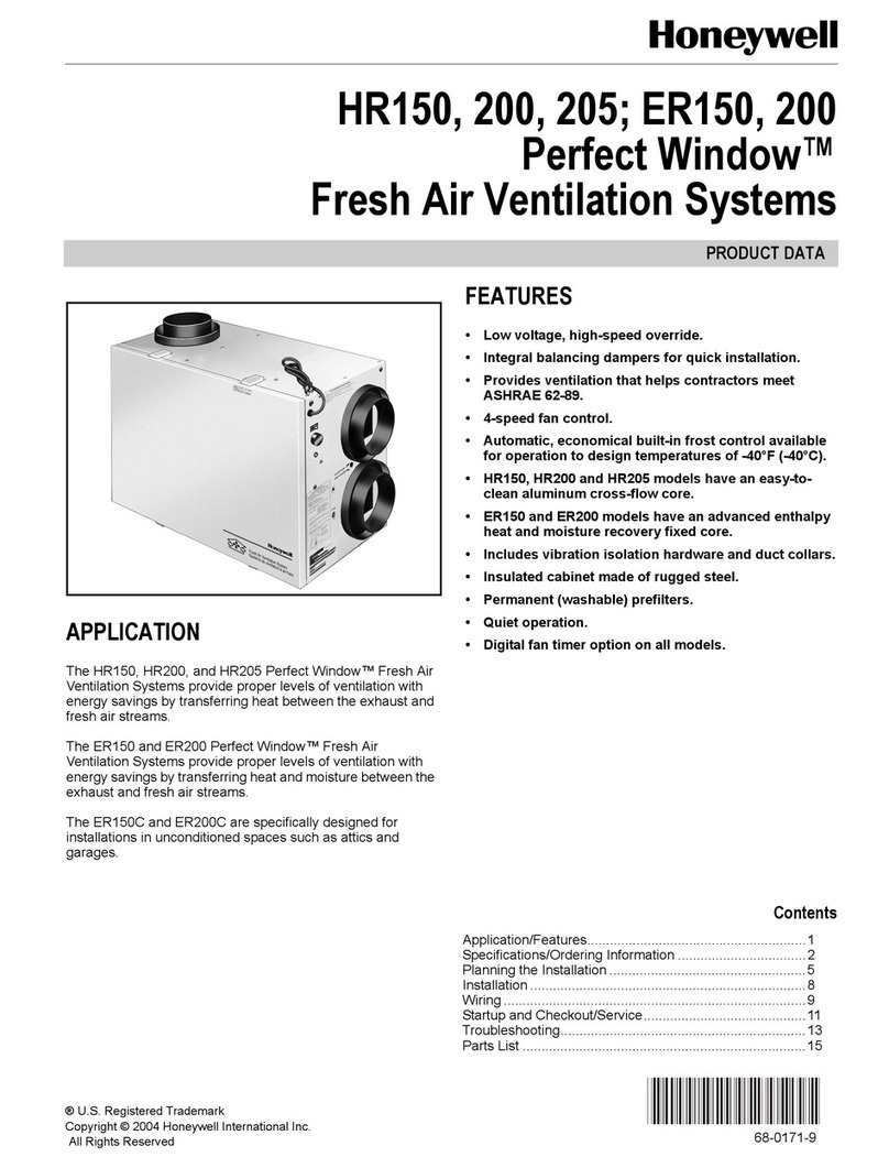
Honeywell
Honeywell PERFECT WINDOW HR150 Product data

Reece
Reece KADO 250 installation instructions
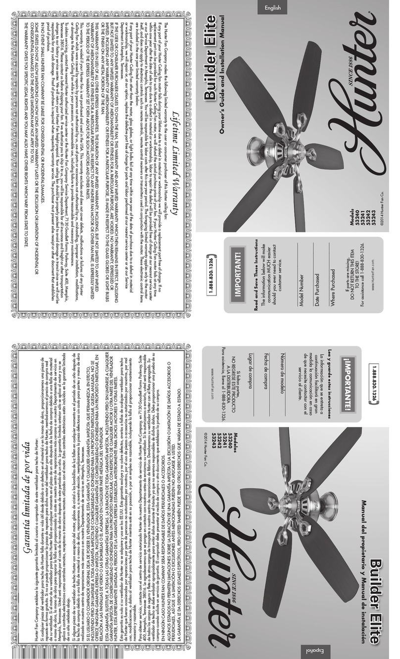
Hunter
Hunter 53240 Owner's guide and installation manual
