Nexans Blackbox G.652 User manual

BLACKBOX G.652
AVEC PLATEAU DE LOVAGE
WITH COILING PLATE
Document : ABS1431/B
Date : 14/03/2017
NOTICE DE MISE EN ŒUVRE
IMPLEMENTATION MANUAL
Tous les schémas, dessins, spécifications, plans et détails de poids, tailles et dimensions figurant dans la
documentation technique ou commerciale de Nexans ont un caractère purement indicatif et ne sauraient
engager Nexans ou être traités comme constitutifs d’une garantie de la part de Nexans.
All drawings, designs, specifications, plans and particulars of weights, size and dimensions contained in the
technical or commercial documentation of Nexans is indicative only and shall not be binding on Nexans or be
treated as constituting a representation on the part of Nexans.
20225064.png

ABS1431/B
BLACKBOX G.652
Table des matières
2/32
Table Of Contents
1. INTRODUCTION
OVERVIEW .......................................................................................................4
1.1. CARACTÉRISTIQUES TECHNIQUES
TECHNICAL CHARACTERISTICS .................................................................................4
1.2. COMPOSITION
CONTENTS............................................................................................................... 5
1.3. ACCESSOIRES FOURNIS
PROVIDED ACCESSORIES..........................................................................................8
2. ACCÈS AU BOÎTIER
ACCESSING THE CLOSURE ...............................................................................9
2.1. OUVERTURE - FERMETURE DU BOÎTIER
OPENING - CLOSING THE CLOSURE......................................................................... 9
2.2. OUVERTURE - FERMETURE DE L’ORGANISEUR CASSETTES
OPENING - CLOSING THE TRAY ORGANIZER............................................................9
2.3. OUVERTURE DU CAPOT ESCAMOTABLE
OPENING THE REAR COVER .....................................................................................9
3. PRÉPARATION DU BOÎTIER
PREPARING THE CLOSURE .............................................................................10
3.1. MISE EN PLACE DES BOUCHONS ET JOINTS D’ÉTANCHÉITÉ
INSTALLING THE PLUGS AND SEALS........................................................................ 10
3.2. MISE EN PLACE DES ÉTRIERS
INSTALLING THE CLAMPS........................................................................................ 11
3.3. MISE EN PLACE DES VIS DE FIXATION
INSTALLING THE FIXING SCREWS............................................................................11
3.4. PRÉPARATION DES CASSETTES
PREPARING THE TRAYS............................................................................................12
3.5. FIXATION MURALE
WALL MOUNTING ..................................................................................................13
4. CÂBLAGE CÔTÉ RÉSEAU
NETWORK CABLE WIRING ............................................................................13
4.1. PRÉPARATION DU CÂBLE
CABLE PREPARATION .............................................................................................. 13
4.2. MISE EN PLACE DU CÂBLE RÉSEAU
NETWORK CABLE INSTALLATION ............................................................................14
4.3. CHEMINEMENT DU/DES MICRO-MODULE(S) VERS LA/LES CASSETTE(S)
MICROMODULES ROUTING TOWARDS THE TRAYS .................................................19
5. RACCORDEMENT DES CLIENTS
CONNECTING THE CUSTOMERS ....................................................................22

ABS1431/B 3/32
BLACKBOX G.652
5.1. PRÉPARATION D’UN CÂBLE CLIENT
PREPARING A CUSTOMER CABLE ............................................................................ 22
5.2. MISE EN PLACE DU CÂBLE
CABLE INSTALLATION.............................................................................................. 23
5.3. FIXATION DU CÂBLE DANS LE BOÎTIER
FIXING THE CABLE IN THE CLOSURE .......................................................................25
5.4. CHEMINEMENT DU(DES) MICRO-MODULE(S) JUSQU’À LA CASSETTE
ROUTING THE MICROMODULE(S) TOWARDS THE TRAY..........................................26
5.5. ÉPISSURAGE DES FIBRES
FIBRES SPLICING..................................................................................................... 28
6. PRESSURISATION
PRESSURISATION...........................................................................................29
ANNEXES/APPENDICES
A. ORDRE DE RACCORDEMENT DES CÂBLES CLIENTS
CONNECTION ORDER OF THE CUSTOMER CABLES .......................................30
B. TABLEAU DE CORRESPONDANCE ENTRE KITS D’ÉTANCHÉITÉ ET DIAMÈTRES
DE CÂBLES CLIENT
TABLE OF CORRESPONDENCE BETWEEN SEALING KITS AND CUSTOMER
CABLES DIAMETRES........................................................................................32
OUTILS NÉCESSAIRES
– Tournevis Torx T25 (6IP) Ø5 mm)
– Tournevis Pozidriv n°2
– Tournevis petit modèle
– Pince coupante spéciale câbles
– Outils de dénudage des câbles et
de préparation des fibres optiques
– Outil coupant
– Ciseaux
– Alcool
– Ruban adhésif
REQUIRED TOOLS
–Torx screwdriver T25 (6IP) Ø5mm
–Pozidriv screwdriver no.2
–Small screwdriver
–Cutting pliers for cables
–Cable stripping and optical fibre
preparation tools
–Cutting tool
–Scissors
–Alcohol
–Adhesive tape

ABS1431/B 4/32
BLACKBOX G.652
1. INTRODUCTION
OVERVIEW
Le boîtier optique Blackbox d’épissurage
et d’extraction a été conçu pour assurer la
protection des épissures de câbles optiques
enterrés,souterrainset aériens.Leboîtierexiste
en version pressurisable.
Un joint placé entre le coffret et son couvercle
assure l’étanchéité du boîtier.
Doté de 4 entrées de câble opérateur, de
4sortiesde câbleclient,d’un plateaudelovage
et d’une à deux cassettes articulées permettant
chacuneleraccordement de12 fibres,leboîtier
a été conçu pour recevoir jusqu’à 24 épissures
de fibres G652.
The Blackbox splicing and extraction unit
has been designed to protect buried,
underground, and overhead cable splices.
The unit can be pressurisable.
A seal fitted between the unit and its cover
ensures the tightness of the unit.
The closure is equipped with 4 cable entries
for operator cables , 4 outputs for customer
cables and a coiling plate. It includes one
or two trays, each tray allowing to connect
12 fibres. The closure can shelter up to
24 splices of G652-type fibre.
1.1. Caractéristiques techniques
Technical characteristics
– Poids (à vide): 1 kg
– Température : -20°C/+60°C
– Protection : IP68 / IK09
– Couleur : Noir
– Dimensions (mm) :
–Weight (empty): 1 kg
–Temperature: -20°C/+60°C
–Protection: IP68 / IK09
–Colour: Black
–Dimensions (mm):

ABS1431/B 5/32
BLACKBOX G.652
1.2. Composition
Contents
A. un corps équipé de
1- quatregrenouillèresarticulées
de fermeture du boîtier et de
maintien du capot,
2- quatre tubulures à étanchéité
type presse étoupe pour l’entrée
des câbles clients,
3- deux pattes de fixation pour
une installation en façade ou en
chambre,
4- une valve de pressurisation
duboîtier pourvalider lemontage
correct des kits d’étanchéité,
5- un trou de sécurisation du
capot,
B. un capot arrière pour la fixation
hors tout du câble réseau. Composé
d’une seule pièce, il se fixe sur le corps
du boîtier à l’aide de 6 vis Torx.
Deux joints doubles identiques (6)
sont positionnés dans les logements du
capot arrière et du corps.
A. a body equipped with
1- four articulated draw latches
to lock the closure and hold the
cover into position,
2- four threaded ports with cable
gland-type seals for inlet of the
customer cables,
3- two fixing legs for facade or
chamber mounting,
4- a pressurisation valve to
validate the correct mounting of
the tightness kits,
5- a hole to secure the cover,
B. a rear cover for overall mounting of the
network cable. Made up of a single part, it
is fastened onto the closure using 6 Torx
screws.
Two identical double seals (6) are
mounted in the dedicated slots of the rear
cover and of the body.

ABS1431/B 6/32
BLACKBOX G.652
C. un organiseur comportant
6- un plateau fixe arrimé sur le
fond du boîtier,
7- des pattes de fixation des
câbles clients,
8- des éléments de guidage
central ou latéral des fibres ou
des micro-modules jusqu’aux
cassettes,
9- uneou2 cassettesd’épissurage
et de lovage des fibres clients et
réseau (selon commande),
10- un plateau de lovage des
fibres en passage,
11- des anneaux de lovage,
D. un capot avec un trou (13) permettant
de relier le corps du boîtier à l’aide d’une
cordelette, via le trou de sécurisation (5).
C. an organizer made up of
6- a fixed plate clamped at the
bottom of the closure,
7- fixing legs to clamp customer
cables,
8- guiding parts for central or
lateral routing of the fibres or
micromodules to the trays,
9- one or 2 trays for coiling and
splicing customer and network
fibres (depending on the order),
10- a coiling plate for crossing
fibres,
11- coiling rings,
D. a cover with a hole (13) allowing to bind
together the cover and the closure, using
a cord and hole (5).

ABS1431/B 7/32
BLACKBOX G.652

ABS1431/B 8/32
BLACKBOX G.652
1.3. Accessoires fournis
Provided accessories
Désignation Description
Kit de fixation du câble résau composé
de :
- 6 vis autotaraudeuses M5 x 25 mm,
- 2 vis autotaraudeuses ST4 x 12 mm,
- 2 étriers pour la fixation des mèches
aramides,
- 2 colliers métalliques pour la fixation
des câbles,
- 4 colliers plastiques type rilsan pour la
fixation des bouchons.
Kit for fixing the network cable
made up of:
- 6 M5x25mm self-thread screws
- 2 ST4x12mm self-thread screws
- 2 plates for fixing the aramid
yarns
- 2 metallic collars for fixing the
cables
- 4 rilsan-type plastic collars for
fixing the plugs.
Kit de fixation des câbles clients
composé de :
- 12 vis autotaraudeuses ST3,5 x 7 mm
pour la fixation des mèches aramides,
- 16 colliers type rilsan pour la fixation
de la gaine du câble.
Kit for fixing the customer cables
made up of:
- 12 ST3.5x7mm self-thread screws
for fixing the aramid yarns
- 16 rilsan-type collars for fixing
the outer sheath.
Kit de fixation murale composé de :
- 2 chevilles,
- 2 rondelles,
- 2 vis ST5 x 38 mm.
Wall mounting kit made up of:
- 2 anchors
- 2 washers
- 2 ST5x38mm screws.
Kit d’étanchéité du câble résau
composé de :
- 2 joints doubles (non illustrés) instal-
lés sur le capot arrière et au fond du
boîtier,
- 4 bouchons obturateurs,
- 2 longueurs de mastic,
- 2 longueurs de toile abrasive.
Tightness kit for the network cable
made up of:
- 2 double seals (not illustrated)
fitted on the rear cover and inside
the closure
- 4 plugs
- 2 lengths of mastic
- 1 length of abrasive cloth.
Kit d’étanchéité des câbles clients
composé de :
- 4 écrous,
- 4 joints d’étanchéité (voir tableau en
Annexe B),
- des bouchons translucides.
Tightness kit for the customer
cables made up of:
- 4 nuts
- 4 seals (see table of Annex B)
- Translucent plugs.
Kit de fixation des micro-modules
et fibres 900 µm dans les cassettes
composé de :
- 6 peignes clipsables,
- des outils d’aide à la mise en place
des fibres ou micro-modules.
Kit for fixing micromodules and
900µm fibres in the trays made
up of:
- 6 combs with clip mechanism
- Tools to help install the fibres or
micromodules.

ABS1431/B 9/32
BLACKBOX G.652
2. ACCÈS AU BOÎTIER
ACCESSING THE CLOSURE
2.1. Ouverture - fermeture du boîtier
Opening - closing the closure
2.2. Ouverture - fermeture de l’organiseur cassettes
Opening - closing the tray organizer
2.3. Ouverture du capot escamotable
Opening the rear cover
Grenouillère
Draw latch
Appuyer
Push
Patte d’encliquetage
Latching tab
ABS1431/B 10/32
BLACKBOX G.652
3.1. Mise en place des bouchons et joints d’étanchéité
Installing the plugs and seals
3. PRÉPARATION DU BOÎTIER
PREPARING THE CLOSURE
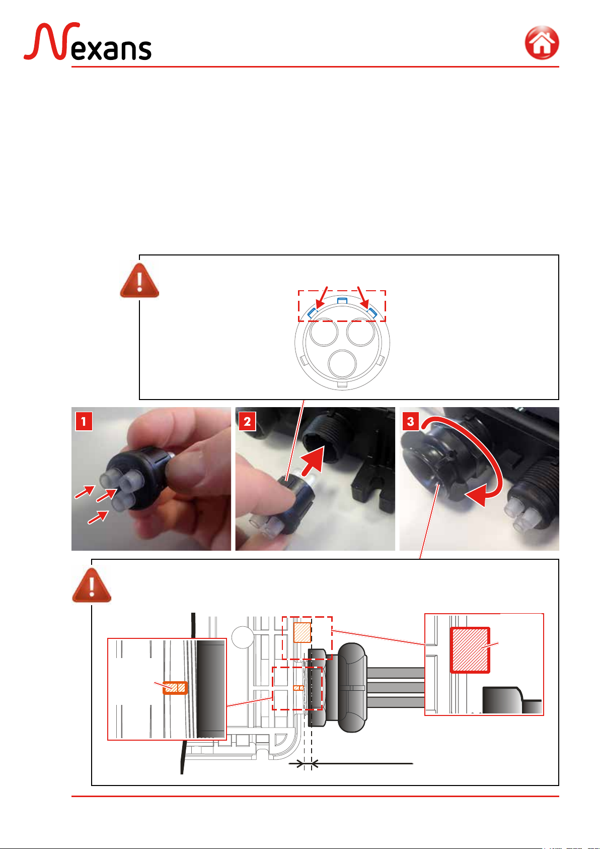
1. Placer les bouchons translucides dans les
joints en poussant jusqu’en butée.
2. Placer les joints dans les tubulures en
respectantl’orientation indiquéeci-contre.
3. Visser manuellement les écrous sur les
tubulures.
1. Push the translucent plugs in the seals
down to the stop.
2. Push the seals in the threaded tubes by
respecting the orientation prescribed.
3. Screw the nuts onto the threaded tubes
by hand.
Pour assurer l’étanchéité du boîtier,
l’écrou doit arriver entre la butée 1
et le repère 2.
MIN.
Repère
2
Mark 2
MAX.
Butée 1
Stop 1
To ensure closure tightness, the
nut must reach the interval be-
tween stop 1 and mark 2.
Intervalle de serrage
Tightening interval
Les joints sont
indexés. HAUT
TOP
BAS
BOTTOM
2 sections rapprochées
2 closer sections The seals are
indexed.

ABS1431/B 11/32
BLACKBOX G.652
3.2. Mise en place des étriers
Installing the clamps
3.3. Mise en place des vis de fixation
Installing the fixing screws
Mettre en place les vis de fixation des porteurs
des câbles clients.
Install the screws for fixing the customer
cables strength members.
Visser complètement sans forcer. Tighten completely but without force.
Orientate the clamps as illustrated
to allow rear cover clipping.
Orienter les étriers comme illus-
tré pour permettre la clipsation
du capot arrière.
Installer les étriers de fixation des aramides ou
des porteurs sur le capot arrière.
Mount on the rear cover the clamps allowing
to fix the aramid yarns or strength members.

ABS1431/B 12/32
BLACKBOX G.652
3.4. Préparation des cassettes
Preparing the trays
1. Enleverle papierdeprotectionducouvercle
en plexiglass de la cassette supérieure.
2. Détacher les volets de la cassette et les
clipser à chaque entrée de la cassette.
3. Mettre en place les peignes fournis dans
le kit.
1. Remove the paper from the plexiglass cover
of the upper tray.
2. Remove the shutters of the tray and clip
them at each entry of the tray.
3. Install the combs provided in the kit.
Volet
Shutter
12 x Ø 250µm
Peigne en mousse pour
micromodule
Foam comb
Outil à détacher
Tool to detach
25 x Ø 900µm
Peigne spécial
pigtails
Special comb for
pigtails

ABS1431/B 13/32
BLACKBOX G.652
3.5. Fixation murale
Wall mounting
Fixer directement le boîtier sur un mur à l’aide
des vis et chevilles fournies dans le kit.
Fix the box on the wall using the screws and
anchors provided in the kit.
En cas de fixation sur un poteau en
bois, utiliser des vis tire-fond (non
fournies).
In case of mounting on a wooden pole,
use coach screws (not provided).
1. Enlever la gaine du câble sur 250 cm.
2. Couper les mèches aramides à
20 cm de la gaine et les tresser
sur 10 cm en terminant par un
noeud.
3. Couper le porteur à 8 cm de la
gaine. Dénuder si nécessaire 2,5
cm pour le passage sous l’étrier.
1. Remove the cable sheath on 250cm.
2. Cut the aramid yarns 20cm away
from the sheath. Plait the aramid
yarns on 10cm and stop with
a node.
3. Cut the strength member
8cm away from the sheath.
Unstrip it if necessary on
2.5cm for locking under the clamp.
4. CÂBLAGE CÔTÉ RÉSEAU
NETWORK CABLE WIRING
4.1. Préparation du câble
Cable preparation
Câble réseau
Network cable
Micro-modules
Micromodules Noeud
Node
Mèches aramides tressées
Plaited aramid yarns
20 cm
10 cm
8 cm
250 cm
20 cm
10 cm
8 cm
Porteur
Strength member
ABS1431/B 14/32
BLACKBOX G.652
2. Nettoyer à l’alcool.
3. Couperleslongueursdemasticd’étanchéité
nécessaires en fonction du diamètre de
câble, comme indiqué dans le tableau
ci-dessous.
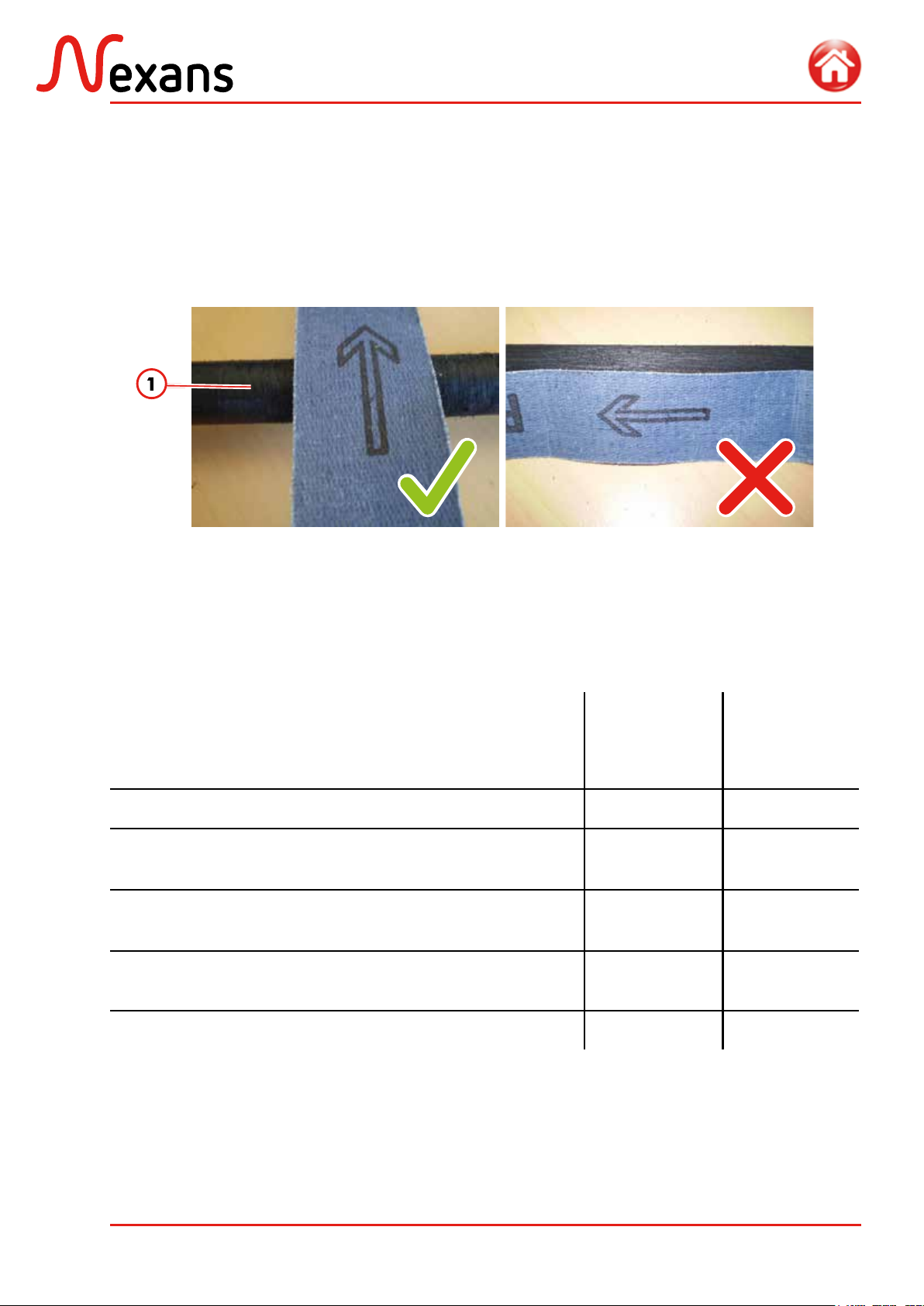
1. Abraser la (les) gaine(s) de câble à l’aide
dela toilefournie(1), perpendiculairement
à l’axe du (des) câble(s) sur 3 cm depuis
l’extrémité.
1. Abrade the cable sheath using the cloth
(1) provided, in a perpendicular position to
the cable, 3cm away from the cable end.
2. Clean with alcohol.
3. Cut the required lengths of sealant
according to the cable diameter, as shown
in the table below.
4.2. Mise en place du câble réseau
Network cable installation
Type de câble
Cable type
Diamètre des
câbles (mm)
Cables diameter
(mm)
Longueur de
mastic (mm)
Sealant length
(mm)
4-6 70
L 1091 mod 6 (6 et/and 12FO); L1092 mod 6 (6 et/and 12FO)
L 1092 mod 12 (12,24 et/and 36FO); L 1018 (6 et/and 12 FO) 6-8 60
L 1091 mod 6 (18 à/to 48 FO); L 1092 mod 12 (24 et/and 36 FO)
L 1091 mod 12 (48 et/and 72 FO). 8-10 50
L 1091 mod 6 (54 à/to 72 FO); L 1092 mod 6 (42 à/to 72 FO)
L 1092 mod 12 (48 à/to 72 FO) 10-14 45
14-15 40

ABS1431/B 15/32
BLACKBOX G.652
4. Poser le mastic sur la gaine extérieure, à
10 mm de l’extrémité de la gaine.
4. Apply sealant on the sheath at a distance
of 10mm from the sheath end.
5. Positionner le mastic sur les rainures
crantées du joint d’étanchéité.
6. Fixer la gaine extérieure du câble sur
le capot à l’aide d’un collier métallique
Serflex (2).
5. Install the sealant on the ribbed grooves
of the seal.
6. Clamp the cable sheath onto the rear cover
using a Serflex metallic collar (2).
10 mm
Enrouler le mastic autour du
câble et sur lui-même en le
tendant légèrement.
Roll the sealant around the cable
and on itself by stretching it
slightly.
Bien faire adhérer le mastic à
la gaine du câble lors du début
de la pose.
When starting to apply the
sealant, make it strongly
adhere to the cable sheath.
10 mm

ABS1431/B 16/32
BLACKBOX G.652
7. Répéter l’opération pour fixer la gaine du
deuxième câble (3).
8. Serrer les vis pour bloquer les renforts
souples tressés sous l’étrier.
7. Repeat the procedure to clamp the second
cable sheath (3).
8. Tighten the screws to block the aramid
yarns under the clamp.
Fig. Arrimage en épi
Butt midspan
9. Mettre en place des bouchons (4) sur les
entrées non utilisées et les arrimer à l’aide
des colliers plastiques (5) fournis.
9. Insert the plugs (4) on the unused
entries and clamp them using the plastic
collars (5) provided.
Attention à l’orientation des
étriers. Voir section 3.2.
Pay attention to the orientation of
the clamps. See section 3.2.
Fig. Piquage en épi
Butt midspan
Utiliser les colliers plas-
tiques grand format.
Use the largest plastic
collars.
Placer les bouchons en
butée contre la gorge, à
l’INTÉRIEUR de la gorge.
Gorge
Groove
Install the plugs into abut-
ment against the groove,
INSIDE the groove.

ABS1431/B 17/32
BLACKBOX G.652
Fig. Piquage droit
Straight midspan
10. Couper au ras de la gaine les micro-
modules qui seront acheminés dans les
cassettes.
10. Cut level with the sheath the micromodules
to be routed towards the trays.
11. Passer les micro-modules à travers le
boîtier et pré-fixer (encliqueter) le capot
amovible sur le fond du boîtier.
11. Route the micromodules through the closure
and pre install (by clipping) the removable
cover at the rear of the closure.

ABS1431/B 18/32
BLACKBOX G.652
13. Mettre en place et serrer les 4 autres vis :
si le serrage a été correctement effectué,
le capot doit être en butée contre le
fond du boîtier.
13. Install and tighten the 4 other screws: if
the tightening is correct, the rear cover
must rest firmly against the closure.
Contact entre le fond
et le capot esca-
motable lorsque le
serrage est optimisé.
When the tightening is
correct, the closure and
the removable cover must
rest against each other.
12. Fixer le capot amovible sur le boîtier à
l’aide des 6 vis fournies, en commençant
par les 2 vis centrales.
12. Fasten the removable cover onto the closure
using the 6 screws provided , starting with
the two central screws.
Vis centrales à serrer en
premier.
Central screws to be tightened
first.
SERRAGE
INSUFFISANT
TIGHTENING
TOO LOOSE
SERRAGE
CORRECT
CORRECT
TIGHTENING

ABS1431/B 19/32
BLACKBOX G.652
A. Acheminer tous les micro-modules à
travers le boîtier jusqu’au plateau de
lovage.
A. Route all the micromodules through the
closure to the coiling plate.
Respecter le rayon de courbure
minimum de la fibre.
4.3. Cheminement du/des micro-module(s) vers la/les cassette(s)
Micromodules routing towards the trays
Respect the minimum bending ra-
dius of the fibre.
Fig. Cheminement des micro-modules dans le boîtier - Piquage épi
Routing of the micromodules in the closure - Butt midspan
Passage
dans les
pattes de
guidage
Routing in
the guiding
legs

ABS1431/B 20/32
BLACKBOX G.652
B. Lover les micro-modules dans le plateau
en terminant par un S.
C. Couper les micromodules à raccorder au
centre du plateau (milieu du S) et délover
les micro-modules.
B. Coil the micromodules in the plate by
performing a S-shaped loop.
C. Cut the micromodules to be connected at
the centre of the plate (at the centre of
the S shape) and uncoil the micromodules.
Fig. Lovage des fibres en passage - Piquage épi
Coiling of crossing fibres - Butt midspan
Plateau de lovage
Coiling plate
Lovage
en « S »
‘S‘-shaped
coiling
Couper ici
Cut here
Table of contents
Other Nexans Conference System manuals


