AURATON 3003 User manual

AURATON 3003
Owner’s Manual
for software version F0F
3003
www.auraton.pl

3
Congratulations on purchasing a wired temperature controller
based on cutting-edge technological solutions.
AURATON 3003
FrostGuard function
protects the room against freezing
Option to temporarily reduce the programmed
temperature
For 6 hours, every day at the same time.
Backlit LCD display
Backlit display makes it possible to supervise the device
operation even in poorly lit rooms.
LCD
5
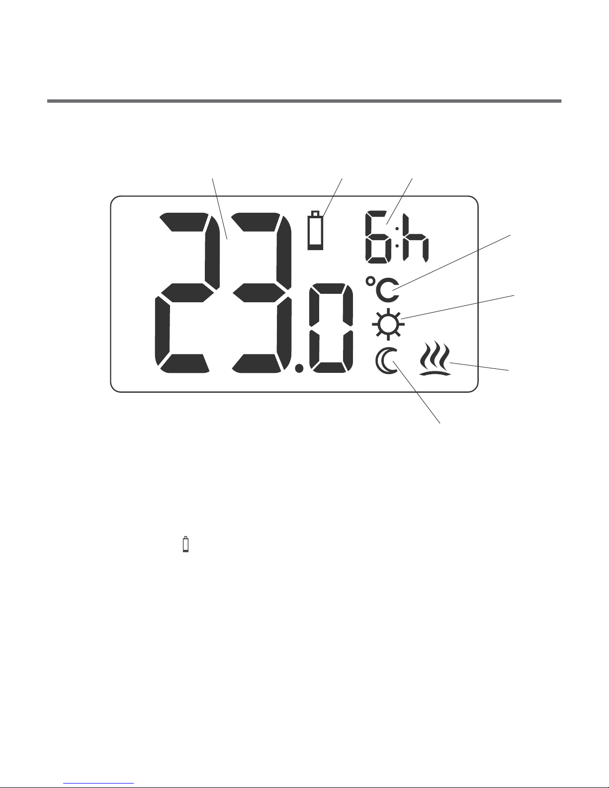
Display
1 2 3
4
5
6
7
1. Temperature
In normal mode, the controller displays the temperature in the
room in which it is installed.
2. Battery low ( )
This symbol appears when the battery voltage has dropped
below the acceptable level. Replace the battery ASAP.
NOTE: to maintain the settings the battery replacement should
last less than 30 seconds.
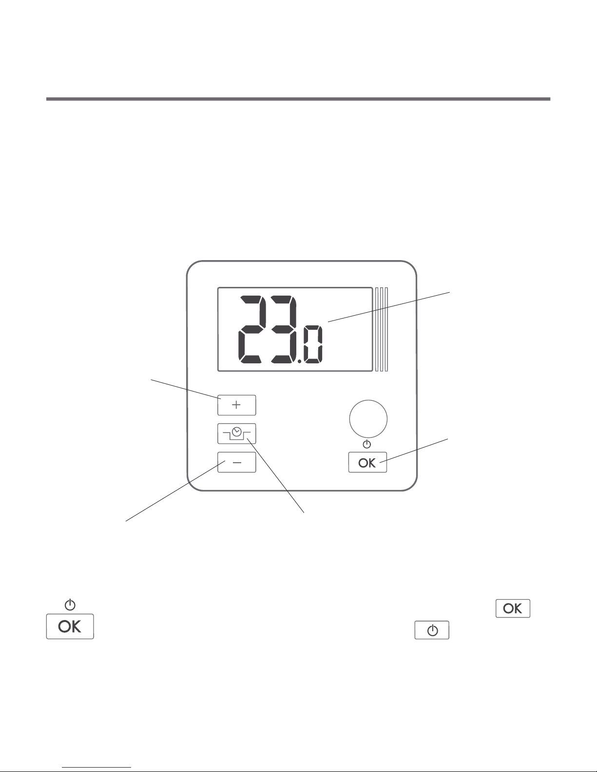
Description of AURATON 3003 temperature
controller
AURATON 3003
LCD display
The front panel of the enclosure includes a backlit LCD display and
four function buttons.
4
increase
temperature
button
temporary temperature
reduction button
confirm
or controller
ON/OFF button
reduce
temperature
button
ź
ź
press briefly – confirm the temperature setting
press and hold – controller ON/OFF
5
Display
1 2 3
4
5
6
7
1. Temperature
In normal mode, the controller displays the temperature in the
room in which it is installed.
2. Battery low ( )
This symbol appears when the battery voltage has dropped
below the acceptable level. Replace the battery ASAP.
NOTE: to maintain the settings the battery replacement should
last less than 30 seconds.
Description of AURATON 3003 temperature
controller
AURATON 3003
LCD display
The front panel of the enclosure includes a backlit LCD display and
four function buttons.
4
increase
temperature
button
temporary temperature
reduction button
confirm
or controller
ON/OFF button
reduce
temperature
button
ź
ź
press briefly – confirm the temperature setting
press and hold – controller ON/OFF

7
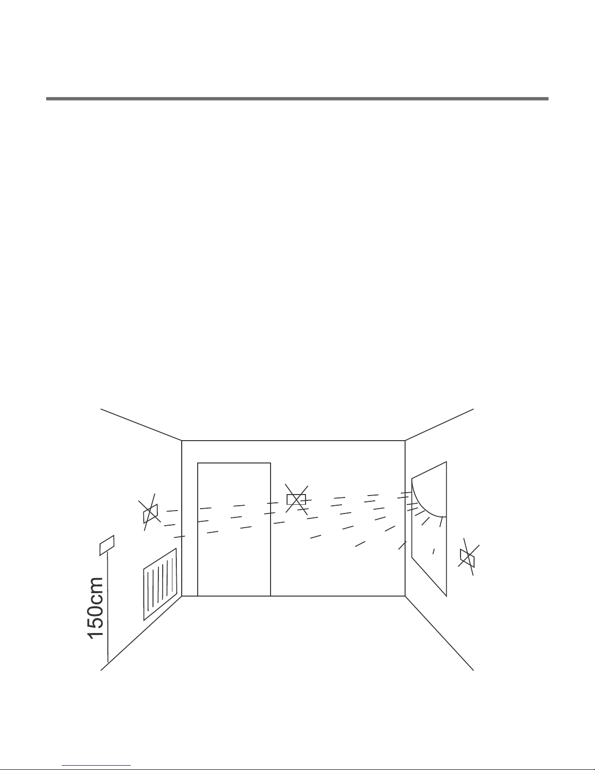
Location can significantly affect the controller operation. Controller
located in a place with no air circulation or exposed to direct sunlight
may not work correctly. Install the controller on the internal wall of
the building (partition wall), in a place with air circulation. Avoid
installing it in the vicinity of heat generating devices (TV set, heater,
fridge) or in places exposed to direct sunlight. Installing the
controller near a door may also cause problems as the controller will
be exposed to vibrations.
Selecting a correct location
for the AURATON 3003 temperature controller
6
3. Temporary temperature reduction time
This symbols shows how long the temporary temperature
reduction mode will be on.
4. Temperature unit ( )
Shows that the temperature is displayed in degrees Celsius.
5. Indicator that the temporary temperature reduction
is programmed ( )
Indicates that the user has programmed the temporary
temperature reduction mode. It appears when the mode is not
currently on, but the function of temporary temperature
reduction is active (more information in the “Setting the
temporary temperature reduction mode” section).
6. Controller on indicator ( )
Indicates the device status. It appears when the controlled
equipment is turned on.
7. Indicator of temporary temperature reduction mode ( )
Appears when the temporary temperature reduction program is
running.
7
Location can significantly affect the controller operation. Controller
located in a place with no air circulation or exposed to direct sunlight
may not work correctly. Install the controller on the internal wall of
the building (partition wall), in a place with air circulation. Avoid
installing it in the vicinity of heat generating devices (TV set, heater,
fridge) or in places exposed to direct sunlight. Installing the
controller near a door may also cause problems as the controller will
be exposed to vibrations.
Selecting a correct location
for the AURATON 3003 temperature controller
6
3. Temporary temperature reduction time
This symbols shows how long the temporary temperature
reduction mode will be on.
4. Temperature unit ( )
Shows that the temperature is displayed in degrees Celsius.
5. Indicator that the temporary temperature reduction
is programmed ( )
Indicates that the user has programmed the temporary
temperature reduction mode. It appears when the mode is not
currently on, but the function of temporary temperature
reduction is active (more information in the “Setting the
temporary temperature reduction mode” section).
6. Controller on indicator ( )
Indicates the device status. It appears when the controlled
equipment is turned on.
7. Indicator of temporary temperature reduction mode ( )
Appears when the temporary temperature reduction program is
running.

9
lead terminals
3.
NO COM NC
lead
terminals
NC
COM
NO
It is a typical single-pole two-state relay. In most cases, the NC
terminal is not used.
NOTE: After connecting the leads replace the plastic cover.
cover
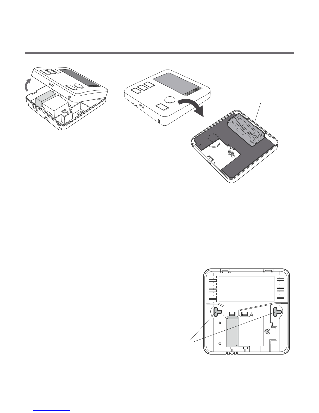
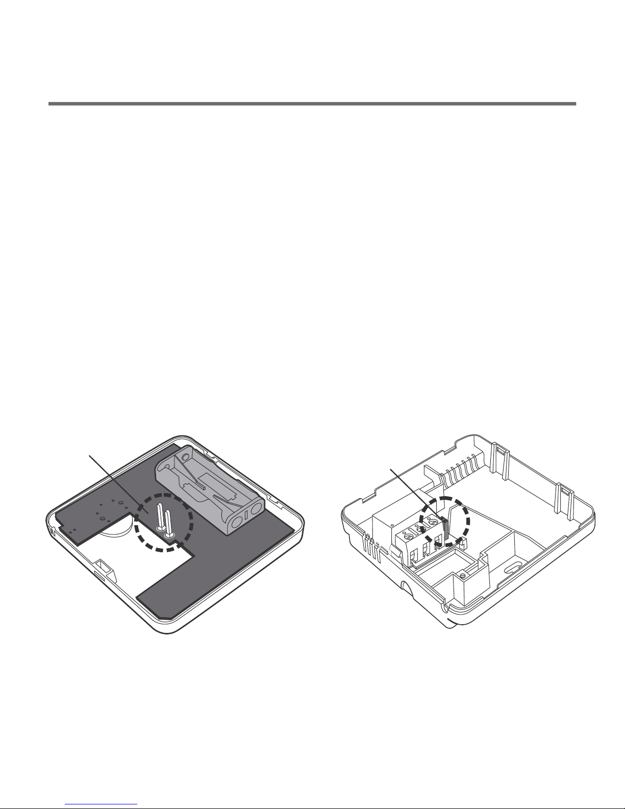
Installing/replacing batteries
The battery compartment is located inside the controller, in the
front part of the enclosure. To place the batteries remove the front
panel as shown in the section ”Connecting the leads to
AURATON 3003”.
8
Connecting the leads to AURATON 3003
To connect the leads remove the front panel as shown below:
1. 2.
The lead terminals are on the controller's back wall, under the
plastic cover.
cover
screw
1. 2.
1. 2.

9
lead terminals
3.
NO COM NC
lead
terminals
NC
COM
NO
It is a typical single-pole two-state relay. In most cases, the NC
terminal is not used.
NOTE: After connecting the leads replace the plastic cover.
cover
Installing/replacing batteries
The battery compartment is located inside the controller, in the
front part of the enclosure. To place the batteries remove the front
panel as shown in the section ”Connecting the leads to
AURATON 3003”.
8
Connecting the leads to AURATON 3003
To connect the leads remove the front panel as shown below:
1. 2.
The lead terminals are on the controller's back wall, under the
plastic cover.
cover
screw
1. 2.
1. 2.
11
3. Place the expansion plugs into the drilled holes (plugs are
included in the kit).
4. Fasten the rear panel to the wall using the screws included
in the kit.
5. Replace the front panel.
NOTE: In case of wooden wall you don't have to use expansion plugs. Just drill
the 2.7 mm dia holes (instead of 6 mm) in screw the bolts directly into the
wood.
FRONT PANEL REAR PANEL
Placing the front panel: NOTE
When replacing the front panel onto the rear panel pay attention to
the pin connection which transmits the control signals.
Pins Pin socket
When replacing the front cover make sure that the pins are
inserted into the pin socket.
10
battery
compartment
2x AAA 1.5 V
Put two AAA 1.5V batteries into the
compartment, observing the polarity.
To fasten the AURATON 3003 controller to the wall::
1. Remove the controller front panel (as shown in the section
”Connecting the leads to AURATON 3003”).
2. Drill two 6mm dia holes in
the wall (set the holes spacing
using the controller rear panel).
Fastening the controller on the wall
NO COM NC
opening
for the screw

If for any reason you want to have the temperature in
the room reduced by 3°C every day at the same time,
then you can do it for 6 hours. To reduce the
temperature:
1. Press the button and hold it for
3 seconds.
The display will show the symbol of
moon ( ) and the hour counter ( ).
2. The controller goes to the temporary
temperature reduction mode and
every day at the same time it will
reduce the temperature by 3°C for 6
hours.
2. Using the and buttons set the desired temperature
in the room with the 0.2°C accuracy.
3. Confirm your settings by briefly pressing the button.
Setting the temporary temperature
reduction mode
1312
First start of the controller
After a correct placement of batteries
in the compartment all segments will
appear on the display for a second
(display test), followed by the software
version number.
The current temperature in the room
will be displayed after a moment.
The controller is ready for operation.
Setting the temperature
NOTE: T
the display backlight on, only the second pressing activates a
given function.
To set the required temperature in the normal operation mode:
1. Press the or button.
The temperature display segment will
go into the edit mode and will start
flashing.
he first pressing of any function button always turns

The AURATON 3003 controller features a special FrostGuard
function which prevents freeze damage to your room. The function
is activated when the controller is off.
When the controller is off and the temperature in the room drops to
2°C, the display will show the symbols Fr ( ) and , and the
relay will activate. When the temperature rises to 2.2°C the display
will turn off again and the relay will disconnect the contacts.
15
FrostGuard function
NOTE: After 6 hours the controller will revert to the basic
temperature setting. On the display the moon symbol ( )
will be replaced by the sun symbol ( ).
NOTE: The temporary temperature reduction mode always starts
when the function is activated. This means that the possible
temporary temperature reduction should be programmed
at the time when you want the temperature change to
happen.
Switching off the temporary temperature reduction mode
To switch off the temporary temperature reduction mode, press and
hold this button for 3 seconds.
The display will show the current temperature in the room and the
controller will revert to the normal mode of operation.
14
Changing hysteresis
Hysteresis prevents the device from switching on too often due to
insignificant temperature fluctuation.
E.g. with HI2 hysteresis and temperature setting of 20°C, the boiler
switches on at 19.8°C and switches off at 20.2°C. With HI4 hysteresis
and temperature setting of 20°C, the boiler switches on at 19,6°C
and switches off at 20.4°C.
To change hysteresis, press ,
and simultaneously and
hold for 3 seconds. When hysteresis
change mode is active, message HI is
displayed.
Use and to change hysteresis settings.
HI 2 – ±0,2°C (factory setting)
HI 4 – ±0,4°C
HI P – PWM mode (see chapter “PWM mode”)
Press to confirm your selection.
The controller resumes normal operation.
(++++)
(----) (xxxxx)
(+++++) (-------)
[OKkkk]

1716
ź
ź
ź
You can switch on and off the controller any time by briefly
pressing the button.
The first pressing of any function button always turns the display
backlight on, only the second pressing activates a given
function.
During programming, failure to press any button for 10 seconds
is the same as pressing the button .
Notes
Pulse-Width Modulation mode (PWM)
When changing hysteresis settings, you can enable PWM mode.
In PWM mode, the controller switches on the heating device in
cycles to minimize temperature fluctuations. The controller
monitors the temperature rise and drop time.
Temperature
Time
Preset
temperature
Room
temperature
With these values determined, the controller switches the heating
device on and off in cycles that enable maintaining temperature as
close to the setpoint as possible.
CAUTION: In PWM mode, the controller can switch on the heating
device even though the temperature in the room is higher than
preset temperature. This is because the PWM algorithm tries to
maintain the preset temperature and stays ahead of the heating
system behaviour.
Technical specification
Operating temperature: 0 – 45°C
Temperature measurement range: 0 – 35°C
Temperature control range: 5 – 35°C
Hysteresis: ±0,2°C /
Default temperature setting: 20°C
Additional function: FrostGuard
Operation cycle:daily
Operation status indication:LCD
Maximum load current ~ 16A 250VAC
on relay contacts:
Power supply:2x AAA 1.5V
alkaline batteries
±0,4°C / PWM
Disposal
The controller bears the WEEE crossed waste bin mark. According
to the Directive 2002/96/CE and the Waste Electrical and
Electronic Equipment Act, this marking means that after its life
such equipment may not be disposed of together with the
household waste.
The user should deliver it to a collection centre of waste
electrical and electronic equipment.
18

www.auraton.pl
Table of contents
Other AURATON Thermostat manuals

AURATON
AURATON Auriga User manual

AURATON
AURATON 2100 TX User manual

AURATON
AURATON R30 RT User manual

AURATON
AURATON 2005 User manual

AURATON
AURATON Libra User manual

AURATON
AURATON T-1 RT User manual

AURATON
AURATON Tucana User manual

AURATON
AURATON 1300 User manual

AURATON
AURATON 2020 User manual

AURATON
AURATON 2005 TX User manual


Popular Thermostat manuals by other brands

Honeywell
Honeywell Prestige THX9321R01 operating manual

JUMO
JUMO B 70.1050.0 operating instructions

Lux Products
Lux Products P711 Installation and operation instructions

Aube Technologies
Aube Technologies TH115 A owner's guide

Pelican
Pelican TCM1 installation guide

Heatmiser
Heatmiser PRTHW-TS operating instructions


