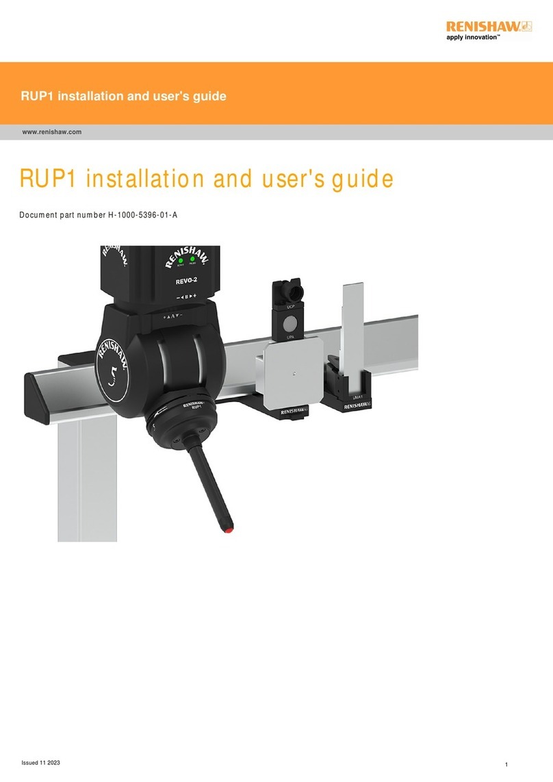
Metal Work ONE User guide

BEDIENUNG UND WARTUNG
USE AND MAINTENANCE

2
TECHNISCHE DATEN
Durchfluss bei 6.3 bar (0.63 Mpa; 91 psi)
Nl/min
∆p 0.5 bar (0.05 Mpa; 7 psi) scfm
Durchfluss bei 6.3 bar (0.63 Mpa; 91 psi)
Nl/min
∆p 1 bar (0.1 Mpa; 14 psi) scfm
Durchfluss bei Entlüftung bei 6 bar Nl/min
(0.6 Mpa; 87 psi) scfm
1/4” Durchfluss an der Luftabnahme Nl/min
(ungeregelte Luft) bei 6.3 bar scfm
(0.63 Mpa; 91 psi) ∆p 1 bar
*Durchfluss jeder Luftabnahme Nl/min
1/4” für gefilterte und geregelte scfm
Luft bei 6.3 bar
(0.6 Mpa; 91 psi) ∆p 1 bar
Medium
Einstellbereich des Druckes bar
Filterfeinheit mm
Maximaler Eingangsdruck bar
Betriebstemperaturbereich °C
°F
Schutzart
Isolationsklasse der Spule
Einschaltdauer
Elektrischer Anschluss
Leistungsaufnahme W
Elektrische Spannung / Magnetspule V
Einstellbereich des Druckschalters bar
Hysterese des Druckschalters (nicht einstellbar)
bar
Maximale Strombelastbarkeit des Druckschalters
A
Betriebsspannung des Druckschalters V
Schaltfunktion des Druckschalters
Lebensdauer / Schaltspiele
Gewicht kg
Wandbefestigung
(Schalttafelbefestigung max. Dicke 10 mm)
Einbaulage
Durchflussrichtung
1/4’’ 3/8’’ 1/2’’ 3/4’’ 1’’
2200 2900 3600
78 102 127
2400 3300 4000
85 116 141
1600
56
1800
64
2400
85
Druckluft
0.5 ÷ 2; - 0.5 ÷ 4; - 0.5 ÷ 8
5 (gelb) oder 20 (weiß)
10 (1 Mpa - 145 psi)
-10 ÷ 50
-14 ÷ 122
IP 65 mit Steckdose
F155
100% ED
M12 x 1.5-polig
nach CEI IEC 60947-5-2
3/0.3
24 DC± 10%
0.5 ÷ 10
0.4 bis 0.8 (siehe Diagramm)
0.5 (Vor Überlastung und Kurzschluss geschützt)
3 ÷ 30 AC/DC
Schließer (NO)
und Öffner (NC)
5 x 10⁶
Von 1.15 bis 1.25 je nach Konfiguration
Von vorn mit M5x 75 Schrauben oder von
hinten mit M6 x 70 Schrauben Die Schrauben
sind Bestandteil der Leiferung
Vertikal
Von links nach rechts
* Der Gesamtdurchfluss aller Luftabnahmen und des Hauptflusses kann den Wert
von 4000 Nl/min bei 6.3 bar mit ∆P=1 nicht überschreiten!
TECHNISCHE SPEZIFIKATIONEN SPECIFICATIONS
TECHNICAL DATA
Flow rate at 6.3 bar (0.63 Mpa; 91 psi)
Nl/min
∆p 0.5 bar (0.05 Mpa; 7 psi) scfm
Flow rate at 6.3 bar (0.63 Mpa; 91 psi)
Nl/min
∆p 1 bar (0.1 Mpa; 14 psi) scfm
Flow rate on discharge at 6 bar Nl/min
(0.6 Mpa; 87 psi) scfm
1/4” port flow rate of non-regulated Nl/min
filtered air at 6.3 bar scfm
(0.63 Mpa; 91 psi) ∆p 1 bar
*Flow rate of each supplementary Nl/min
1/4” filtered and regulated scfm
air port at 6.3 bar
(0.6 Mpa; 91 psi) ∆p 1 bar
Fluid
Setting range bar
Degree of filtration mm
Maximum inlet pressure bar
Operating temperature range °C
°F
Class of protection
Insulation class of the solenoid valve
Switching time
Electrical connector
Solenoid valve power W
Solenoid valve voltage V
Pressure interval settable on the bar
pressure switch
Pressure switch hysteresis (not adjustable) bar
Maximum pressure switch current A
Maximum pressure switch voltage V
Pressure switch contacts
Number of switching
Weight kg
Wall fixing (max. panel thickness 10 mm)
Mounting position
Direction of flow
1/4’’ 3/8’’ 1/2’’ 3/4’’ 1’’
2200 2900 3600
78 102 127
2400 3300 4000
85 116 141
1600
56
1800
64
2400
85
Compressed air
0.5 ÷ 2; - 0.5 ÷ 4; - 0.5 ÷ 8
5 (yellow) or 20 (white)
10 (1 Mpa - 145 psi)
-10 ÷ 50
-14 ÷ 122
IP 65 with connector
F155
100% ED
M12 x 1 5-pin to
CEI IEC 60947-5-2
3/0.3
24 DC± 10%
0.5 ÷ 10
0.4 to 0.8 (see diagram)
0.5
(protected against overload and short-circuit)
3 ÷ 30 AC/DC
Normally open (NO)
and Normally closed (NC)
5 x 10⁶
from 1.15 to 1.25 according to configurations
Front, with M5x 75
screws or back, with M6 x 70 screws
The screws are included in the supply
Vertical
From left to right
* Total flow rate from two supplementary outlets and the main one cannot exceed
4000 Nl/min at 6.3 bar with ∆P=1

3
DURCHFLUSSDIAGRAMME
3/8”
Druckfluss / Flow rate
Pm = 8 bar - 0.8 MPa - 116 psi
Einstelldruck / Preset pressure
psi Mpa bar
0
1
500
Nl/min
bar
1000 1500 2000 2500 3000 3500
2
3
4
5
6
0.5
1.5
2.5
3.5
4.5
5.5
6.5
0
12040 10060 80200
scfm
psi
0.7
60
70
80
90
100
0
10
20
30
40
50
MPa
0
0.1
0.2
0.3
0.4
0.5
0.6
7
1/4”
Druckfluss / Flow rate
Pm = 8 bar - 0.8 MPa - 116 psi
Einstelldruck / Preset pressure
psi Mpa bar
bar
Nl/min
02
500500100015002000
1
2
3
4
5
6
0.5
0
1.5
2.5
3.5
4.5
5.5
6.5
psi
7
0.7
scfm
060804020
60
70
80
90
100
0
10
20
30
40
50
MPa
0
0.1
0.2
0.3
0.4
0.5
0.6
1/2” - 3/4” - 1”
Druckfluss / Flow rate
Pm = 8 bar - 0.8 MPa - 116 psi
Einstelldruck / Preset pressure
psi Mpa bar
bar
1
2
3
4
5
6
0.5
1.5
2.5
3.5
4.5
5.5
6.5
0
0 4000 4500500100015002000250030003500 Nl/min
40 10060 80200
scfm
120140
psi
0.7
60
70
80
90
100
0
10
20
30
40
50
MPa
0
0.1
0.2
0.3
0.4
0.5
0 .6
7
FLOW CHARTS

4
Es gibt 3 Möglichkeiten:
MONTAGE FIXING
BEDIENUNG
1. Von vorn
Mit M5 x 75 Schrauben.
Es werden mitgeliefert:
2 Schrauben M5 x 75
2 Scheiben 5 x 10
2 Muttern M5
2. Von hinten
Mit M6 x 70 Schrauben.
Es werden mitgeliefert:
2 Schrauben M6 x 70
2 Scheiben 6 x 12,5
(die M6 Muttern sind vorhanden)
3. Schalttafel
In diesem Falle muss der
Montagesatz für
Schalttafelmontage bestellt
werden Bestellnummer:
9200702
ONE wurde zur Druckluftwartung konstruiert.
Es darf kein anderes Medium ohne
ausdrückliche Zustimmung durch Metal Work
verwendet werden!
Vorzugsweise ist UNGEÖLTE Luft zu
verwenden.
Wenn Aktoren existieren, die eine
Schmierung benötigen, ist ein Öler hinter der
ONE, so dicht wie möglich an den zu
ölenden Aktoren zu montieren.
MEDIUM FLUID
NEIN / NO
JA / YES
ONE has been designed to treat compressed
air.
No other fluid can be used without express
authorisation by Metal Work.
It is preferable to use UNLUBRICATED air.
If there are devices requiring lubrication,
it is advisable to install the lubricator
downstream ONE as close as possible to the
devices involved.
There are three possible:
1. At the front
with M5 x 75 screws.
The supply includes:
No. 2 screws M5 x 75
No. 2 washers 5 x 10
No. 2 nuts M5
2. At the rear
with M6 x 70 screws
The supply includes:
No. 2 screws M6 x 70
No. 2 washers 6 x 12,5
(the M6 nuts are included
in the group)
3. Panel
In this case the kit of “panel
mounting brackets” must be
purchased Code 9200702
HOW TO USE

5
A - Nicht geregelte, gefilterte Luftabnahme
Dazu ist ein Anschluß 1/4” links oben, der
Luft hinter dem Filter und vor dem Regler, den
Ventilen und dem Druckschalter abnimmt.
Dieser kann zum Beispiel für den Betrieb einer
Druckluftpistole genutzt werden.
Der A7 - Gewindestöpsel ist zu entfernen.
HINWEIS: Druckluftversorung abschalten, bevor
der Stöpsel entfernt wird.
Wenn keine andere Methode möglich ist, dann
ist der Deckel des Filters zu entfernen und das
automatische Abschaltventil unterbricht dann
die Luftzufuhr zum Filter.
B - Geregelte, gefilterte Luftabnahmen
Dazu sind die Anschlüsse 1/4” oben und unten
rechts am Gehäuse, die parallel zum
Druckluftausgang hinter dem Regler, den
Ventilen, dem Druckschalter usw. geschaltet
sind, zu verwenden. Die entsprechenden
Gewindestöpsel sind zu entfernen.
HINWEIS: Druckluftversorgung abschalten,
bevor die Stöpsel entfernt werden.
Es ist lediglich das manuelle V3V Ventil zu
betätigen, wenn vorhanden oder die elektrische
Versorgung abzuschalten. Wenn keine andere
Möglichkeit vorhanden ist, so ist der Deckel
des Filters zu entfernen und das automatische
Abschaltventil unterbricht dann die Luftzufuhr
zum Filter.
ZUSÄTZLICHE LUFTABNAHME
A - Non-regulated filtered air intake
This is a 1/4” port situated at the top on the left
that takes air downstream of the filter before the
regulator and the valves, pressure switches, etc.
It is used for example for a compressed air gun.
To use it, remove the A7 plug.
NB: switch off the compressed air supply before
removing the plug. If there is no alternative
method, unscrew the filter plug, the automatic
valve incorporated in the unit will cut off air
flow after the filter.
B - Regulated filtered air intakes
There is a 1/4” port at the top on the right and
one bottom right, connected in parallel the main
threaded outlet port, so downstream of the
regulator, the valves, the pressure switch and so
on. To use it, remove the A7 plug.
NB: switch off the compressed air supply before
removing the plug. Merely turn the manual V3V
valve, if there is one, to off, or switch off the
electricity supply to any solenoid valves. If there
is no alternative method, unscrew the filter plug,
the automatic valve incorporated in the unit will
cut off air flow after the filter.
Die Anschlüsse sind durch Drehen der
ausgezeichnet geeigneten
Gewindeverschraubungen der ONE (A)
zu verbinden.
Setzen Sie die Einheit keinen Querkräften
oder Drehmomenten aus, die diese zerstören
könnten (B).
GEWINDEANSCHLÜSSE THREADED PORT CONNECTION
A
B
Connect the ports to the thread by rotating
the fitting or ONE’s rotary threaded port as
most appropriate (A).
Do not subject the unit to transversal stresses
or tilting torques that may damage it (B).
AB
G1/4” G1/4”
B
G1/4”
SUPPLEMENTARY AIR INTAKES

6
Ein integriertes effizientes System entfernt das meiste Kondensat aus der
Druckluft und sammelt dies in einem Sichtbehälter unten an der Einheit.
Dieses Wasser muss abgelassen werden.
Bei Ablass “RMSA” muss die Druckluftversorgung von Zeit zu Zeit
abgeschaltet werden, um das Kondensat abzulassen.
Alternativ muss die Ringmutter am Ablass manuell gedreht werden.
Bei vollautomatischem Ablass (RA) wird das Kondensat immer dann
abgelassen, wenn das Niveau im Behälter erreicht wird, bei dem das
Schwimmerventil anspricht.
Zur Beförderung des ablaufenden Wassers einen Schlauch mit 6 mm
Innendurchmesser im unteren Bereich einsetzen.
HINWEIS: Wenn der Durchmesser des Schlauches zu klein ist, oder
es gibt Biegungen oder Engstellen, so kann das Wasser nur schlecht
abfließen und der automatische Ablass funktioniert nicht exakt.
KONDENSATABLASS CONDENSATE DRAIN
An efficient internal system separates most of the water condensate in the
compressed air and collects it in a clear bowl at the bottom of the unit.
This water has to be drained out.
If an RMSA device is present, the compressed air supply must be
switched off periodically to drain out the condensate or, alternatively, the
ring nut must be pushed upwards by hand.
If there is an automatic drain RA, the condensate is drained out
automatically whenever the level in the bowl reaches the point of
intervention of the float valve.
To convey the draining insert the pipe having internal diameter 6 mm in
the lower part.
NB: If the diameter of the pipe is too small, or there are bends or
bottlenecks, it is difficult for the water to flow through it and the
automatic drain does not work properly.
The semi-auto
condensate drain is
the normally open
type. When there
is pressure in the
bowl, the drain
closes. When there
is no pressure in the
bowl,
it opens and the
condensate drains out.
Wenn es notwendig
ist, ist es auch möglich
das Kondensat unter
Druck abzuleiten. Die
einfache manuelle
Bewegung “Ventil
nach oben drücken”
ermöglicht den
Kondensatablass.
Bei Drehung des
Knopfes im
Uhrzeigersinn, wird
das Ventil verrastet
und es kann nur
dann arbeiten, wenn
der Knopf in die
zentrale Position
gestellt wird.
RMSA RA
ONE hat ein einziges Druckentlüftungsventil unten an der Einheit.
Abluft wird freigesetzt, wenn:
1. Das manuelle V3V geschlossen ist.
2. Das elektrische V3V oder APR abgeschaltet ist.
3. Der Sekundärdruck am Regler den Einstellwert überschreitet.
Das Entlüftungsventil hat einen Gewindeanschluss 1/4” mit einem
Schalldämpfer in Metallgeflecht.
Wenn die Abluft geführt werden soll, so ist der Schalldämpfer durch eine
geeignete Verschraubung zu ersetzen. Ein Schlauch mit mindestens 6 mm
Durchmesser wird dazu empfohlen.
ENTLÜFTUNG AIR EXHAUST
Entlüftung 1/4” / Air exaust G1/4”
ø mindestens 6 mm / ø at least MIN 6 mm
ONE has a single compressed air relief valve at the bottom.
Downstream air is discharged when:
1. The V3V manual valve is closed.
2. The V3V electric valve or the APR is switched off.
3. The downstream pressure exceeds the reading on the regulator.
The exhaust valve has a 1/4” threaded port supplied standard with a
metal mesh silencer.
If you wish to convey the air out, replace the silencer with a suitable
fitting. A pipe with a diameter of at least 6 mm is recommended.
Der halbautomatische
Ablass ist normal
offen. Wenn Druck
im Behälter ist,
schließt der Ablass.
Wenn kein Druck
im Behälter ist,
öffnet er sich und
das Kondensat wird
abgeleitet.
If necessary, it is
possible to drain the
condensate whilst
the bowl is
pressurised.
The simple manual
operation of
“pushing up the
valve” will allow the
condensate to drain.
When rotating the
button clockwise,
the valve becomes
in locked position,
and can only work
when the button
is returned to the
central position.

7
Es ist nur ein 5-poliger Stecker M12 x 1 für die Versorung des Magnet-
ventiles und die Übertragung der Druckschaltersignale erforderlich.
Auch wenn eine dieser Funktionen nicht benutzt wird, ist dieser 5-polige
Stecker vorhanden. Die Pins sind wie in nebenstehendem Diagramm
gezeigt, anzuschließen.
Der elektrische Kreis des Druckschalters ist durch eine rücksetzbare
Sicherung vor Überlastung geschützt. Wird die Sicherung ausgelöst, wird
das elektrische Signal unterbrochen, die LEDs bleiben aber eingeschaltet.
Zur Wiederherstellung des Betriebs muss die Stromversorgung unterbro-
chen und der Grund der Störung behoben werden.
Nachstehend die Farbfolge für die Varianten Stecker mit Kabel
W0970513002 und W0970513004:
1 - braun
2 - weiß
3 - blau
4 - schwarz
5 - grau
ELEKTRISCHER ANSCHLUSS ELECTRICAL CONNECTION
A single 5-pin M12x1 connector is used to supply the solenoid valve
and handle the pressure switch signals.
Even if one of these functions is not present, it is always a 5-pin
connector. Only the correct connectors must be connected as shown in
the diagrams below.
The electrical circuit of the pressure switch is protected against overloads
by a resettable fuse. In the case of intervention, the electrical signal is
interrupted but the LEDs stay on.
To restore operation, disconnect the power supply and remove the cause
of failure.
Herewith you will find the sequence of the colours for the versions
of the connector with cable W0970513002 and W0970513004:
1 - brown
2 - white
3 - blue
4 - black
5 - gray
Ausführung mit Magnetventil und Druckschalter
Version with solenoid valve and pressure switch Ausführung allein mit Druckschalter
Version with pressure switch
Ausführung allein mit Magnetventil
Version with solenoid valve
Die - ONE elektrisch - hat immer drei LEDs, jedoch arbeiten nur
die, für die die betreffenden Funktionen aktiviert sind.
- ON: GRÜNE LED. Anzeige der Betriebsbereitschaft des V3V-Ventiles
oder des Softstartventiles (APR).
-NC:ROTE LED. Der Druckschalter ist geöffnet. Dies gilt, wenn der
tatsächliche Druck kleiner ist als der Einstellwert des Druckschalters
und der elektrische Stromkreis geöffnet ist.
- NO:GELBE LED. Der Druckschalter ist geschlossen. Dies gilt, wenn der
tatsächliche Druck höher ist als der Einstellwert des Druckschalters
und der elektrische Stromkreis geschlossen ist.
LEDs LEDs
The ONE electrical unit always has three LEDs, but only those associated
with the current functions are active.
- ON: GREEN LED. On if the electric V3V valve or the APR is powered
on.
- NC:RED LED. Pressure switch’s normally-closed contact. It is on if the
actual pressure is lower than the pressure switch setting and if an
electrical circuit is connected.
- NO: YELLOW LED. Pressure switch’s normally-open contact. It is on if
the actual pressure is higher than the pressure switch setting and if
an electrical circuit is connected.
Leds

8
Wenn das Filter so verschmutzt ist, dass ein starker Druckanstieg
beim Druckluftdurchfluss entsteht, hebt sich die orange Anzeige
einige Millimeter von der Oberfläche der Einheit.
Diese bleibt nur dann sichtbar, wenn ein Druckabfall wirksam ist.
Wenn z.B. der Durchfluss absinkt, kann sich die Anzeige zurückstellen.
FILTERVERSCHMUTZUNGSANZEIGE CLOGGED FILTER SIGNAL
If the filter gets so clogged up that it causes an excessive drop in pressure
as the air passes through, the orange indicator will project from the body
by a few millimetres.
It only remains visible while there is effectively a drop in pressure.
If for example the required flow rate drops, the indicator will retract.
im Falle einer Anzeige / in course of signalling
Die Filterpatrone ist horizontal eingebaut. Um diese auszuwechist
lediglich der Deckel von vorn abzuschrauben. Die Einheit bebesitzt
ein automatisches Abschaltventil, für den Fall der Entfernung
des Deckels. Der Eingangsdruck muss nicht abgeschaltet
werden und es besteht kein Risiko, dass der Deckel weggeschleudert
wird. Da die Luft in der Patrone von innen nach außen fließt,
sammelt sich der Schmutz in der Patrone und greift nicht die anderen
Oberflächen an.
Es ist jedoch immer ratsam, den Sitz der Patrone und den Deckel zu
reinigen.
Wird der Deckel wieder eingesetzt, sollte dieser mit einem maximalen
Drehmoment von 6 Nm angezogen werden, um ihn nicht zu zerstören.
Falls erforderlich Imbusschlüssel 8 mm verwenden.
FILTER FILTER
The filter cartridge is positioned horizontally. To replace it, merely
unscrew the plug on the front. The unit contains an automatic on-off
valve, so the valve closes automatically when you remove the plug.
There is no need for a tap upstream and there is no risk of the plug
being blown out.
Considering that the air in the cartridge flows outwards, the dirt collects
inside the cartridge and does not affect the other internal surfaces.
It is always advisable, however, to clean the inside of the unit and the
plug.
When you replace the plug, tighten it to a maximum torque of 6 Nm,
taking care not to damage it. Use an 8-mm Allen wrench if necessary.
5 µm (gelb), 20 µm (
weiß
) / 5 µm (yellow), 20 µm (white)
8
NEIN / NO
JA / YES

9
MANUELLES 3/2-WEGEVENTIL (V3V)
ELEKTRISCHES 3/2-WEGEVENTIL (V3V)
1. Es ist der Knopf bis zum gewünschten Wert am Manometer zu drehen.
2. Dann ist der Knopf hinein zu drücken um ihn zu arretieren.
Durch eine gesteuerte Entlüftung ist die Regelung verbessert.
HINWEIS: Der Druck in Standardreglern muss immer von kleineren zu
größeren Werten eingestellt werden.
1. Turn the knob until you read the desired value on the gauge.
2. Then press the knob to lock it.
Controlled air relief is provided to improve the pressure regulation.
NB: the pressure in standard regulators must always be set upwards.
DRUCKREGELUNG PRESSURE REGULATION
1 2
V3V MANUAL VALVE
Wenn das Ventil in der On-Position steht, ist die Luftzufuhr eingeschaltet.
Wenn das Ventil in der Off-Position steht, wird die Luftzufuhr
abgeschaltet und die Einheit wird entlüftet.
Wenn es sich um die verschießbare Version handelt, kann das Schloss
bei Off eine Drehung des Schalters verhindern.
HINWEIS: Wenn zusätzlich ein elektrisches V3V oder APR vorhanden
ist, so kann die Luftzufuhr nur erfolgen, wenn diese Ventile auch
eingeschaltet sind.
When the valve is in the On position, the air supply is enabled.
When the valve is in the Off position, the air supply is shut off and the
air downstream is discharged.
If the V3V valve is the padlock type, you can attach the padlock when the
valve is on Off to present it from being rotated.
NB: if there is also an electric V3V or APR, the air supply is only enabled
if the power supply is on.
On Off
Wenn dieses Ventil eingeschaltet ist, ist die Luftzufuhr vorhanden.
Bei unbetätigtem Ventil wird die Druckluftzufuhr gestoppt und die
Einheit wird entlüftet.
Das Ventil kann auch ohne elektrische Betätigung geschaltet wer-
den, indem der Testknopf gedrückt wird. Es ist eine monostabile
Betätigung, die beim Loslassen in die Ausgangslage zurück geht.
HINWEIS: Wenn zusätzlich ein manuelles V3V-Ventil integriert ist,
wird die Luftzufuhr nur eingeschaltet, wenn dieses auch geöffnet ist.
When this valve is powered on, the air supply is enabled.
When the power supply is switched off, the compressed air supply is cut
off and air downstream is relieved.
The valve can also be opened without powering it on by pressing the test
button. This is a monostable button which returns to the closed position
when released.
NB: if there is also a manual V3V valve, the air supply is only enabled if
it is in the On position.
V3V ELECTRIC VALVE

10
Das Softstartventil der ONE ist gänzlich verschieden, von denen, die
gegenwärtig auf dem Markt bekannt sind. Der Druck steigt unabhängig
vom Durchfluss der Aktoren allmählich an.
Wenn das Magnetventil (bei der elektrische Variante) oder das manuelle
V3V-Ventil (bei der nichtelektrischen Variante) auf On betätigt wird,
beginnt der Ausgangsdruck zu steigen.
Wenn er etwa 30-40% des geregelten Wertes erreicht, öffnet sich das
Ventil vollständig und der Druck steigt bis zum geregelten Wert an.
Die Flanke des Druckanstieges kann exakt mit dem Drehknopf vorn
eingestellt werden.
1. In Richtung “Slow” erhöht sich die Zeit des Druckaufbaues.
Bei Drehung bis zum Anschlag bleibt der Ausgangsdruck auf Null und
der Druck erhöht sich nicht.
2. In Richtung “Quick”verkürzt sich die Zeit bis das Ventil vollständig
öffnet. Bei Drehung bis zum Anschlag öffnet das Ventil nahezu sofort.
Die Softstartfunktion ist dann deaktiviert.
Nach der Einstellung ist der Drehknopf hineinzudrücken, um diesen zu
verrasten.
SOFTSTARTVENTIL (APR) SOFT START VALVE (APR)
ONE’s soft start valve is completely new compared to others currently on
the market. The pressure is increased gradually whatever the flow rate of
the utilities.
When the solenoid valve is powered on (if there is an electric soft start
valve) or you turn the manual V3V valve to On (if there is a non-electric
soft start valve), the downstream pressure starts to increase.
When it reaches about 30-40% of the set value, the valve opens
completely and the pressure rises to the set value.
The pressure increase can be regulated with precision on the knob on the
front:
1. Turn in the “Slow”direction to increase the ramp time.
If you rotate as far as it will go, this cuts off the flow of air completely,
and the pressure does not increase.
2. Turn in the “Quick” direction to decrease the time it takes to open the
valve. If you rotate as far as it will go, the valve will open almost
immediately, deactivating the progressive actuator function.
After regulation, press the knob to lock it.
Der Druckschalter hat elektrische Schaltkontakte, die es ermöglichen
zwischen “normal offen” oder “normal geschlossen” zu wählen.
Die Anzeige dazu erfolgt über die LEDs NC und NO, die ansprechen,
wenn der tatsächliche Druck kleiner oder größer als der eingestellte Wert
ist. Die LEDs sprechen nur an, wenn die elektrische Versorgung (max 0.5 A)
angeschlossen ist (siehe Abschnitt zu LEDs).
Der elektrische Kreis des Druckschalters ist durch eine rücksetzbare
Sicherung vor Überlastung geschützt. Wird die Sicherung ausgelöst, wird
das elektrische Signal unterbrochen, die LEDs bleiben aber eingeschaltet.
Zur Wiederherstellung des Betriebs muss die Stromversorgung unterbro-
chen und der Grund der Störung behoben werden.
Die Einstellung erfolgt mit einer Rändelschraube. In Richtung “+” erhöht
sich der Ansprechdruck und umgekehrt.
Für eine korrekte Einstellung ist folgendes zu beachten:
- Die Schraube bis zu Anschlag nach “-“ drehen.
- Einstellen des Druckwertes, bei dem der Druckschalter ansprechen soll
und Ablesen des gewünschten Druckes. Die gelbe LED leuchtet und die
rote LED leuchtet nicht.
- Den Dehknopf in Richtung “+” drehen bis rote LED aufleuchtet.
- Drehknopf drücken, um ihn zu verrasten
- Mit dem Regler zum normalen Betriebsdruck zurückkehren.
DRUCKSCHALTER PRESSURE SWITCH
The pressure switch has a switching contact, which means you can have
a normally-open signal or a normally-close signal. It is also connected
to the NC and NO LEDs which come on if the actual pressure is less or
greater than the set pressure, respectively.
The LEDs only come on if an electric charge (max 0.5 A) is connected to
them, as shown in the diagram (see subsection on LEDs).
The electrical circuit of the pressure switch is protected against overloads
by a resettable fuse. In the case of intervention, the electrical signal is
interrupted but the LEDs stay on. To restore operation, disconnect the
power supply and remove the cause of failure.
Regulation is by means of the knurled knob. Turn towards “+”to increase
the pressure and vice versa.
Proceed as follows to make a correct setting.
- Turn the knob towards “-“as far as it will go.
- Set on the pressure regulator the value at which you wish the pressure
switch to activate and read it on the gauge. The NO LED is on and the
NC LED is off.
- Turn the knob towards “+”until switching takes place.
- Press the knob to lock it.
- Reset the desired value for normal operation on the pressure regulator.

11
SCHALTPLAN DES DRUCKSCHALTERS / PRESSURE SWITCH WIRING DIAGRAM
DRUCKSCHALTER -HYSTERESE-DIAGRAMM / PRESSURE SWITCH HYSTERESIS CHART
Niedriger Schaltdruck (bar)
Low switching pressure (bar)
Hoher Schaltdruck (bar)
High switching pressure (bar)
Den Drehkopf vom Druckschalter abziehen. Die Sicherungskappe
einlegen und den gewünschten Schaltpunkt einstellen.
Dann die Sicherungskappe fest in die Endlage pressen.
Wenn eine nochmalige Verstellung notwendig wird, ist die Kappe seitlich
mit einem Schraubendreher lösbar (A).
SICHERUNGSKAPPE SECURITY KNOB
Pull outwards to remove the knob from the APR/pressure switch on the
unit. Insert the security knob and regulate the APR/ pressure switch. Then
press the handle firmly to lock it in position. If the APR/pressure switch
needs to be reset, remove the security knob by forcing it laterally with a
screwdriver (A).
A

12
Als einzige kontinuierliche Wartung ist die Filterpatrone auszuwechseln.
Dies geschieht, wie im Abschnitt “FILTER” erläutert.
Die Einheit kann manchmal eine besondere Wartung erfordern.
Im folgenden sind einige Beispiele und Abhilfen aufgeführt:
1. REGLER
2. FILTER
3. DRUCKSCHALTER
The only routine maintenance required is replacement of the filter
cartridge. Refer to the section entitled “FILTER” for instructions.
The unit may sometimes require extraordinary maintenance.
A few examples and possible remedies are given below.
1. REGULATOR
2. FILTER
3. PRESSURE SWITCH
PROBLEM URSACHE ABHILFE
1.1 Der Regler bläst Luft
über das Entlüftunsventil
ab
Ausgangsdruck ist höher
als der eingestellte Druck Die Entlüftung ist beendet, wenn
der Druck ausgeglichen ist
1.2 Der Regler bläst Luft
über das Entlüftungsventil
ab
Die Entlüftung an der
Betätigung des Pilot- reglers
läßt hörbar eine Luftmenge
entweichen
Dies ist kein Fehler. Es ist für
diese Art Druckregler normal
1.3 Der Regler erreicht
nicht den erforderlichen
Druckwert
Eingangsdruck ist höher als
der Einstellwert
Einstelldruck zu klein
Zu starke Luftabnahme
Eingangsdruck einstellen
Einstellwert am Regler prüfen
Vergleichen der
Druck/Durchfluss-Diagr-amme
für Regler im Katalog
1.4 Feinregelung ist
nicht möglich Einstelldruck zu hoch Um die Empfindlichkeit zu
erhöhen, ist ein Regler mit mit
einem Einstellbereich so dicht
als möglich am Einstellwert zu
wählen
1.5 Nach Luftentnahme
ist der Druck geringer als
der eingestellte Wert
Der Regler wurde von
höherem zu niedrigem
Druck eingestellt
Der Druck ist aufsteigend -von
niedrigem zu höherem Wert
einzustellen
1.6 Der Drehknopf läßt
sich nicht bewegen Drehknopf in verrasteter
Position Knopf durch Anheben entrasten
und dann einstellen
PROBLEM URSACHE ABHILFE
2.1 Das Filter mit dem
Kondensatablass RMSA
gibt das gesammelte
Kondensat nicht frei
RMSA -Schraube
geschlossen
Filter steht ständig unter
Druck
Schraube entgegen dem
Uhrzeigersinn drehen und damit
öffnen
Schraube mit der Hand
drücken - Kondensat ablassen
2.2 Reduzierte
Durchflussmenge Filter verschmutzt Filterpatrone ersetzen
PROBLEM URSACHE ABHILFE
3.1 Der Druckschalter
schaltet zu oft Der Einstellwert ist zu nahe
am Regeldruck Den Ansprechwert des
Druckschalters verringern
3.2 Der Drehnopf läßt
sich nicht bewegen
Drehknopf in der verrasteten
Position Knopf durch Anheben entriegeln
und dann einstellen
PROBLEM CAUSE REMEDY
1.1 The regulator
discharges air from the
relief valve
Downstream pressure
higher than set pressure The air relief stops when the
pressures are balanced
1.2 The regulator
discharges air from its
relieving
The controlled relief of
the pilot regulator lets a
quantity of audible air
through
It’s not defect, but it’s normal for
these pressure regulators
1.3 The regulator does
not reach the required
pressure
Upstream pressure lower
than set pressure
Rated pressure too low
Excessive air intake
Regulate pressure upstream
Check the rating of the regulator
Check the pressure/flow rate
charts for the regulator in the
catalogue
1.4 Fine regulation not
possible Rated pressure too high To increase sensitivity, use a
regulator with a rated pressure
as close as possible to the
desired value
1.5 After an air intake,
the pressure is lower
than the preset value
Regulator setting in
descending order (from
high to low pressure)
Pressure must be set in ascending
order (from low to high pressure)
1.6 The knob does not
rotate Knob in locked position Release the knob by pulling it
upwards and then regulate
PROBLEM CAUSE REMEDY
2.1 The filter equipped
with condensate drain
RMSA type, doesn’t
release the accumulated
condensate
RMSA tap closed
Filter continuously
pressurised
Turn tap anticlockwise to open it
Press the tap to drain out
condensate by hand
2.2 Decreased flow rate Filter clogged Replace the filtering element
PROBLEM CAUSE REMEDY
3.1 The pressure switch
intervenes too often The setting value is too
close to the regulated Lower the intervention point of
the pressure switch
3.2 The knob does not
rotate Knob in locked position Release the knob by pulling it
upwards and then regulate
WARTUNG MAINTENANCE

13
4. 3/2-WEGE-ABSCHALTVENTIL (V3V)
5. SOFTSTARTVENTIL (APR)
HINWEIS: Die Wartung ist nur von ausgebildetem und unterwiesenem
Personal auszuführen.
Bevor irgend eine Handlung vorgenommen wird ist die Druckluftversorgung
abzuschalten und der elektrische Anschluss nach lösen der Überwurfmutter
am M12-Stecker zu entfernen.
4. SHUT-OFF VALVE (V3V)
5. SOFT START VALVE (APR)
NB: Maintenance must be carried out by properly qualified and trained
personnel.
Before doing anything, switch off the compressed air supply and cut off
the power supply by unscrewing and removing the connector ring nut.
PROBLEM URSACHE ABHILFE
4.1 Kein Luftdurchgang
Bei der manuellen
Ausführung ist der Schalter
auf OFF gestellt
Die Ansteuerung der
elektropneum. Ausführung fehlt
Den Schalter in die ON-Position
stellen
Sicherstellen, dass die Spule
angeschlossen ist
4.2 Die Druckluft wird
ständig abgelassen Das manuelle V3V steht in
der Position OFF Den Schalter in die ON-Position
stellen
PROBLEM URSACHE ABHILFE
5.1 Kein Luftdurchgang Einstellknopf vollständig
geschlossen
Keine elektrische Ansteuerung
bei der
elektropneumatischen
Ausführung
Die Drossel nach Bedarf öffnen
Prüfen, ob die Spule aktiviert ist
5.2 Das Softstartventil
startet nicht (immer voller
Druck beim Einschalten)
Einstellknopf ist auf Endstel-
lung “Quick”
Nach Bedarf einstellen
5.3 Der Drehknopf läßt
sich nicht bewegen
Drehknopf in der verrasteten
Stellung Drehknopf durch Herausziehen
entrasten und dann einstellen
5.4 Unterbrechung des
elektrischen Signals,
LEDs bleiben aber
eingeschaltet
Auslösung der Sicherung
wegen Überlastung Unterbrechen Sie die
Stromversorgung und beheben
Sie die Störungsursache
PROBLEM CAUSE REMEDY
4.1 No air passes
downstream In the manual version the
knob is in OFF position
In the electropneumatic
version the electric drive
lacks
Put the knob on the ON position
Verify that the electrical coil is
energized
4.2 The air gets
continuously released The manual V3V is in OFF
position Put the knob on the ON position
PROBLEM CAUSE REMEDY
5.1 No air passes
downstream
Regulation knob fully closed
No electrical control in the
electropneumatic version
Open the needles as required
Check that the electric coil is
energised
5.2 The soft start valve
does not start (immediate
full-port passage of air
Regulation knob fully open
Adjust the needles as required
5.3 The knob does not
rotate Knob in locked position Release the knob by pulling it
upwards and then regulate
5.4 Interruption of the
electrical signal but the
LEDs stay on
Intervention of the fuse due
to overload Switch off the power supply and
remove the cause of failure
1. Die beiden M4 x 45 - Schrauben entfernen (A)
2. Den Gewindeanschluss herausnehmen (B)
3. Den Sitz im Gehäuse reinigen
4. Die Dichtung des neuen Gewindeanschlusses fetten (O-Ring) (C)
5. Den neuen Gewindeanschluss einsetzen
6. Die beiden M4x45 - Schrauben wieder einschrauben (A) und darauf
achten, diese nicht zu überdrehen!
ERSATZ EINES DRUCKLUFTANSCHLUSSES REPLACING A THREADED PORT
1. Unscrew the two M4 x 45 screws (A)
2. Extract the threaded port (B)
3. Clean the seat of the body
4. Grease the OR seal (C) of the new threaded port
5. Insert the new threaded port
6. Re-tighten the two M4x45 screws (A) taking care not to overtighten
B C BC
AA

14
1. Die Mutter am Reglerknopf entfernen (A)
2. Den Filterdeckel entfernen (B)
3. Den Knopf des Softstartventiles (C) und des Druckschalters (D)
herausziehen, wobei die Feder am Druckschalter nicht beschädigt
werden darf. Um dies zu sichern, ist der Knopf beim Ziehen auch
seitwärts zu bewegen.
4. Den Schalldämpfer aus der Entlüftung herausschrauben (E)
5. Alle 1/4” A7 Stöpsel (F)
oder andere an den zusätzlichen Luftabnahmen
montierte Fittings entfernen
6. Die 2+2+2 - Schrauben (G) an den 3 Seiten der Abdeckung
herausschrauben
7. Die Abdeckung entfernen (H), indem sie nach vorn abgezogen wird
8. Die Montage erfolgt in umgekehrter Reihenfolge
ENTFERNEN UND MONTIEREN DER ABDECKUNG HOW TO REMOVE AND REMOUNT THE GUARD
1. Unscrew the regulator ring nut (A)
2. Unscrew the filter plug (B)
3. Pull out the soft start valve knob (C) and the pressure switch knob
(D) taking care not to damage the small spring in the pressure
switch. To do this, grip the knob and pull it outwards with force,
helping yourself by pushing sideways.
4. Unscrew the silencer on the exhaust (E)
5. Remove the 1/4” A7 plugs (F) or any fittings mounted from the
supplementary outputs
6. Unscrew the 2+2+2 screws (G) on the three sides of the guard
7. Remove the guard (H) by pulling it from the front
8. Remount the guard following the above operations in the reverse
order
B
C
F
A
1. DIe Abdeckung entfernen
2. Das Manometer herausschrauben (A)
3. Einen geeigneten Dichtwerkstoff an dem neuen Manometergewinde
anbringen (B) z.B. Loctite®242E oder 542
4. Das neue Manometer einschrauben, wobei auf Ausrichtung der
Nulllage zu achten ist
5. Abdeckung wieder montieren
MANOMETERWECHSEL REPLACING THE PRESSURE GAUGE
1. Remove the guard
2. Unscrew the pressure gauge (A)
3. Apply some removable sealant on the thread of the spare pressure
gauge (B) for example Loctite®242E or 542
4. Screw on the new pressure gauge, making sure the markings are
horizonta
5. Remount the guard
B
A
G
D
G
HE
FG

15
1. Die Abdeckung entfernen
2. Den Reglerknopf enfernen (A)
3. Die Glocke mit dem geeigneten Schlüssel herausschrauben (B)
4. Alle Komponenten des Pilotreglers herausnehmen (C)
5. Wenn auch der Reglersitz ausgewechselt werden soll, die beiden
Schrauben (E) und das Sitzelement (D) und den Sitz (F) entfernen
6. Die neuen Teile mit größter Sorgfalt einsetzen
7. Die Abdeckung wieder montieren
AUSTAUSCH DES PILOTREGLERS REPLACING THE PILOT REGULATOR
1. Remove the guard
2. Remove the regulator knob (A)
3. Unscrew the bell (B) using the key provided
4. Remove all the components for the pilot regulator (C)
5. If you wish to replace the poppet as well, unscrew the 2 screws (E)
and remove the poppet presser (D) and poppet (F)
6. Remount the new parts with great care
7. Remount the guard
1. Die Abdeckung entfernen
2. Die beiden Schrauben im Magnetventil herausschrauben (A)
3. Das Magnetventil (B) ersetzen und beachten dass die Dichtung (C)
exakt platziert wird. Wenn notwendig ist diese Dichtung etwas
anzufeuchten oder zu ölen
4. Die Abdeckung wieder montieren
AUSTAUSCH DES MAGNETVENTILES REPLACING THE SOLENOID VALVE
1. Remove the guard
2. Unscrew the 2 screws in the solenoid valve (A)
3. Replace the solenoid valve (B), taking care that the gasket (C)
seats correctly in position. If necessary, wet the gasket or oil it slightly.
4. Remount the guard
B
C
A
D
E
F
B
C
A

16
1. Die Abdeckung entfernen
2. Die beiden Schrauben im Druckschalter herausschrauben (A)
3. Das Manometer entfernen (B)
4. Nach Entfernen der Schraube (Ddie durchsichtige Abdeckung des
Elektronikträgers (C) entfernen. Kleine Mengen Dichtmittel können
leicht entfernt werden.
5. Soll der Träger auch ausgetauscht werden, sind die beiden
Schrauben (E) am M12x1-Stecker zu e
6. Der Druckschalterstecker ist am Träger zu lösen
7. Der neue Druckschalter ist in umgekehrter Reihenfolge zu montieren.
Der O-Ring des Sitzventils ist zu fetten
8. Um die Schutzart IP65 zu erreichen, ist es notwendig neues
Dichtmaterial zu verwenden, weil das alte zerstört ist.
Ein Silikondichtmittel kann zu diesem Zweck verwendet werden.
9. Die Abdeckung wieder montieren
10. Den neuen Druckschalter einstellen, wie oben beschrieben
HINWEIS: Während der Demontage kann das Manometer zerstört
werden. Es sollte immer ein neues Manometer als Ersatzteil vorhanden
sein.
AUSTAUSCH DES DRUCKSCHALTERS REPLACING THE PRESSURE SWITCH
1. Remove the guard
2. Unscrew the 2 screws in the pressure switch (A)
3. Remove the pressure gauge (B)
4. Remove the clear cover of the electronic board (C) unscrewing the
screw at the back (D). There will be some sealant that can be easily
removed
5. If you wish to replace the board as well, unscrew the 2 screws (E)
securing the M12x1 connector and extract the board
6. Disconnect the pressure switch connector on the electronic board
7. Mount the new pressure switch in the reverse order. Grease the OR
seal of the valve
8. To get the class of protection IP65, it is necessary to apply new
sealant where the existing sealant is damaged. A silicon sealant
can be used for this purpose
9. Remount the guard
10. Calibrate the new pressure switch, following the instructions given
above
NB: during the disassembly stage it’s probable that the gauge gets
damaged. Buy one as spare part before effecting the replacement of
the gauge.
BC
D
AE
Es wurde beschrieben, wie Teile, die als Ersatzteile geliefert werden,
ausgetauscht werden können. Weitere Eingriffe sollten während der
Lebensdauer der Einheit nicht notwendig sein. Es ist jedoch wichtig zu
wissen, dass alle Einzelteile der ONE zerlegt werden können. Deshalb
können alle Teile am Ende der Lebensdauer der Einheit recycled werden.
Erfordert die Einheit Wartungsmaßnahmen, die nicht in diesem Handbuch
beschrieben sind, sollte das Verkaufsbüro kontaktiert werden.
Hier können weitere Hinweise zur Selbstwartung bzw. für eine Reparatur
in unserem Hause gegeben werden.
WEITERE EINGRIFFE IN DIE EINHEIT OTHER INTERVENTIONS
We have described how to replace component parts coded as spares.
No other interventions should be required during the life of the unit. It is
important, however, to bear in mind that all the component parts of ONE
can be disassembled. Therefore, at the end of its operating life, you can
recycle all the materials used.
If the unit requires maintenance not covered in this handbook, please
contact Metal Work’s Sales Office. They will either arrange for the
repairs to be made or provide you with full technical details so that you
can do it yourselves.
www.metalwork.eu
ZNEVA9002 DE_EN - IM01 - 05/2021
Other manuals for ONE
2
Table of contents
Other Metal Work Industrial Equipment manuals
