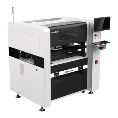
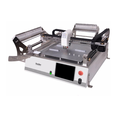
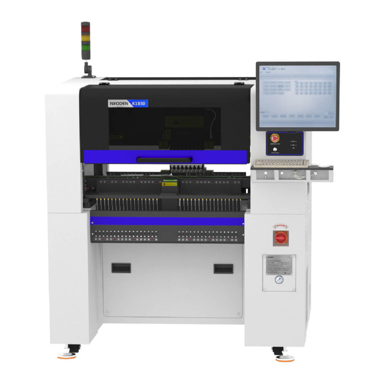
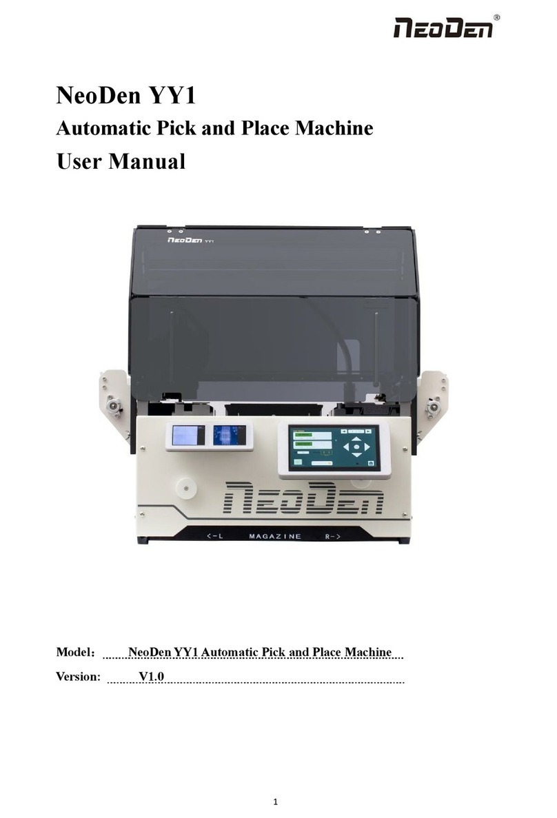
NeoDen NeoDen10 User manual

1
NeoDen10
High Speed Pick and Place Machine
User Manual

2
Model:NeoDen10 High Speed Pick and Place Machine
Version:V1.0

3
Catalog
1. Foreword................................................................................................................................. 5
2. Precautions before using the machine.................................................................................... 5
2.1 Important Notes...............................................................................................................7
2.2Machine Structure of NeoDen10.....................................................................................9
2.3 Machine dimension.......................................................................................................10
2.4 Working area structure..................................................................................................10
2.5 Operation flow chart..................................................................................................... 12
2.6 Flow chart of making a programming file....................................................................13
3. File List Introduction............................................................................................................ 14
4. PCB Information Editing...................................................................................................... 15
4.1 PCB Forward Setting.................................................................................................... 15
4.2 PCB Eject setting.......................................................................................................... 17
5. Panelized PCB Edit...............................................................................................................17
5.1 Panelized PCB origin (SMD1 coordinate)................................................................... 17
5.1.1 Single board:........................................................................................................ 18
5.1.2 Panelized board....................................................................................................19
5.1.3Mirror board..........................................................................................................20
5.2 Introduction of Lock interface......................................................................................21
6. Coordinate information.........................................................................................................22
6.1 PCB Mark setting..........................................................................................................22
6.2 Mark Point information................................................................................................ 23
6.3 Component list setting.................................................................................................. 24

4
6.3.1 Manual programming.......................................................................................... 25
6.3.2 Import the coordinate file.................................................................................... 26
7. Feeder setting........................................................................................................................ 34
7.1 Function of feeder setting interface..............................................................................34
7.2 Feeder Setting............................................................................................................... 35
8. Nozzle Information............................................................................................................... 39
9. Assembly Interface............................................................................................................... 40
10. System Setup.......................................................................................................................44
10.1Feeder Position Configuration.....................................................................................45
10.2 Component Positions Setup........................................................................................47
10.3 Basic Configuration.................................................................................................... 50
11. Manual Test.........................................................................................................................51
12. First trial and test.................................................................................................................52
12.1 Program first dry run...................................................................................................52
12.2 First production test.................................................................................................... 53
12.3 Component Inspection................................................................................................ 53
12.4 Continuous SMT production...................................................................................... 54
13. Structure and maintenance instruction............................................................................... 55
13.1 Feeder Brief Introduction........................................................................................... 55
13.2 Installing tape and reel components........................................................................... 56
13.3 Incorrect installation Samples:................................................................................ 57
14. Maintenance........................................................................................................................ 60
14.1 Take effective measures to reduce /avoid malfunction..............................................61

5
14.2 Maintenance................................................................................................................ 62
14.3 Related issues during solder paste printing process...................................................63
1. Foreword
Sincerely thank you for choosing NeoDen SMT machine.NeoDen10 is designed and used according to the following
purpose---pick and place electric components on PCB. Please do not use this machine for other purposes.
2. Precautions before using the machine
Remove the rust-proof protective film:
In order to prevent rust caused by environmental impact during transportation, we pasted a
protective film in the following parts of the machine as protection (as shown in the figure below).
This protective film needs to be manually removed before the machine is powered on. If there is
any omission, it may cause hidden trouble in operation and damage.
Notice to users:
Dear users, before the equipment starts working, please read the relevant information of this user
manual carefully, so as not to cause equipment failure affecting the use or equipment lifespan
reduction.

6
Figure A Anti-rust protective film
Figure B:rail left and right drive ball screw;
Figure C:Y-axis left and right movement linear guide;
Figure D:rail left and right movement linear guide;
Figure B

7
Figure C Figure D
2.1 Important Notes
Warning of failure risk of camera identification, refer to figure 3 and figure 4: the
following parts are forbidden to touch or strike.
front IC camera back IC camera left mark camera right mark camera
left mark camera light source right mark camera light source
Warning of accuracy failure risk, refer to figure 4: the following parts are
forbidden to touch or strike.
Back to zero point
For the risk of accuracy failure, refer to figure 4: when moving XY axis
manually,pull or push should be performed at the moving force point.

8
figure 6- oil-water separator figure 7-feeder pressure 0.55MP
the air supply shall not be less than 0.6MP
Note: when the pressure input is 0.6MPA, the air flow is 37L/min.It is recommended that users use a compressed air storage
tank of no less than 70L.
Warning of electric shock risk,be sure to follow the requirements below:
Connect to the input power supply that meets the requirements of the
machine, the electrical interface of the machine to the ground must be effectively
grounded.
Any time you enter the case or repair the placement head, you need to shut
down the machine and cut off the power supply.
Warning of machine lifespan reduction risk, be sure to follow the requirements
below:
When installing the machine, the machine must be leveled;
Correct shutdown: first shut down the operating software and the system,
before turning off the main power switch.

9
2.2Machine Structure of NeoDen10
figure 1-Ports and Appearance
(1)Warning Light(Triple Color) (7)USB port
(2)Safety cover (8)Pause button
(3)Front Feeder Slots 1-33(Reference value) (9)Mouse keyboard bracket
(4)Electric Feeder Port (10)Power Switch
(5)Display (11)Air source input
(6)Emergency Button (12)Heavy load pedestal
(8)
(3)
(9)
(12)
(1)
(2)
(4)
(5)
(6)
(7)
(10)
(11)

10
2.3 Machine dimension
figure 2 –machine dimension
2.4 Working area structure
figure 3- Main placement head camera

11

12
figure 4-top view of main mounting area
figure 5-X axis beam(pull and push at the moving force point as above picture)
2.5 Operation flow chart
NO.
Flow chart
Note
1
1. The pick and place machine is a precision equipment. In the
installation position of the machine, it is necessary to carry out horizontal
correction before and after the equipment to prevent the uneven operation
of the equipment from damaging the service life of the equipment;
2. Connect and fix the equipment interface before and after the
equipment, and connect and fix the ground wire;
3. The access power must meet the requirements of power identification;
4. No less than 0.6mp air source input and adjust the pressure value to
OK;
5. Check the safety of the working area of the mounting head;
6. The XY transmission parts are not fastened and interfered, and check
that the emergency stop switch is in normal state;
2
Power on and turn the power switch clockwise;
3
1,1. When the self-test is carried out, the head indicator light of the
mounting head and the light source of the IC camera will be on and
flash briefly to indicate that the self-test is normal;
2,XY initialization (origin reset) is normal, the software enters the file
list interface, and no error report pops up;
4
After power on, directly enter the file list page;
5
See page 10 for the introduction of machine operation for
details;
6
Suggestions on production process:
1. First component confirmation: confirm the component angle
and polarity, component picking position and mounting
position;
2. Start production after confirming solder paste printing and
temperature setting;
7
Production process;
8
After the production is finished, reset the origin and prepare to
shut down;
9
Shut down the system via computer, then power off the
machine.
10
Disconnect the electricity supply after the system being
powered off.
Software shut down
System shut down
Power OFF
Exit
Production Finished
Preparation
Power ON
Automatic
Power on page
Program and Edit;
Production
Shutdown steps
Mounting
Modify
Abnormal
Start-up steps

13
11
Keep the machine clean, daily maintenance of the nozzles
assures high utility.
2.6 Flow chart of making a programming file
Note:
A. The basic procedure of making a programming file by manual programming or import coordinate file is
similar, but there are two different parts: component list and fiducial setting.
B. Please find the detailed operation steps of the differences on relative page.

14
3. File List Introduction
(1) Excel Open:The Excel table of the file can be modified directly in the table for some routine operations,
simplifying the programming operation.
(2) Edit: select a file and click Edit to enter the corresponding editing interface.
(3) Processing: after editing the file and checking the correctness, select the file and click mount button.
(4) Export file: After connecting an U disk, select the file and click Export, after the successful notice pops up, the
export is finished.
(5) Import from U disk: for the files that have been edited offline, they can be directly imported from U disk for
mounting. After connecting U disk, click Import from U disk, select the corresponding files in the new window, and
click OK. When the imported files are showed in the file list, the operation is finished.
(6) Delete: select the corresponding file, click delete, a prompt window will pop up, and click Yes.
(7) Copy: select the corresponding file, click Copy, and the file list will generate a file of xxxcopy1. In order to
prevent misoperation, a new file can be copied before operation.
(8) Add a new file: click Add to open the input window, input the file name, and click OK. At this time, when the file
list interface displays new files, the operation is successful.

15
4. PCB Information Editing
In File List interface, select the file to edit,enter to PCB Information interface, as show in the figure:
First, set the track width,adjust the track width according to the actual PCB width(usually actual PCB width plus
1mm),click Width Set,follow the prompt window to check whether back to zero condition are met.After back to zero, the
track width will be adjusted.After placing the PCB on the track,gently push the PCB back and forth by hand to confirm that
the PCB has a small gap of about 1mm in the track, so that the PCB can pass smoothly.
Secondly,set PCB Forward Position(note:Mag Fixture mode does not need to set Forward Position),click Align,select the
Forward Position according to the image recognized by Mark camera,select the Alignment Method nozzle 1, click save and
back,Forward Position is recorded ans saved.
4.1 PCB Forward Setting
There are three ways in PCB Forward Setting---Mag Fixture,Tracks,Long Tracks
(1)Mag fixture
Select tray to fix the board feeding mode, place the PCB to be installed in the proper position in the mounting area, and then
click "top plate control" to fix the PCB.
(2)Tracks
Select the “Tracks”on PCB Feed Setting interface:

16
Tracks width setting:Set correct PCB width value until the PCB can move smoothly
PCB Feed Test:Put PCB to “Tracks Section 1”,Click “forward”, PCB will move to “Tracks section 2” and stop at the
cylinder thimble position through the sensor,cylinder will raise the PCB, then thimble will go down, PCB feeding complete.
(3)Long Tracks
Select the “Long Tracks”on PCB Forward Setting interface, first enter the number of track segments(each segment
corresponds to a file, the number of the file is corresponding to the number of the segment).Take 3-segment files as an
example, for first file, the number of segment is input 1;for second file,the number of segment is input 2;for third file, the
segment is input 3.
Secondly, set the board Forward Position. When editing long tracks file, only for first file, you need to set Forward
Position,for second file and third file, you do not need to set Forward Position.Finally,click Forward,the track will transport
PCB to the position of cylinder thimble. The blocking pin will block the PCB.The cylinder thimble will raise the PCB. The
blocking pin will return. The board feeding is completed.
The operation method of long tracks placement is as following: (1)In the long track mode(placement of three sections),
three separate files need to be edited.(2)the naming requirements are as follows:add an underscore after the second file
name and the third file name(the underscore is English format)+the corresponding number of the file, there can not be any
space in the file name, the file name is as follows:
When want to do mount of the finished working file,need choose the phase 1 file(e.g. long),then click mount.(the long
tracks also support mount 2 phases,then only need create 2 working files).
Working Step description of Long tracks mode in mounting: The long tracks sends feed signal to the front conveyor,
and feed PCB to cylinder thimble 1 position, cylinder will raise the PCB,then thimble 1 will go down,PCB feeding phase 1
is completed.After above placement is completed, the PCB in the waiting area is released, feed to cylinder thimble 2

17
position, cylinder will raise the PCB,then thimble 2 will go down,PCB feeding phase 2 is completed.After above placement
is completed, the PCB in the waiting area is released, feed to cylinder thimble 3 position, cylinder will raise the PCB,then
thimble 3 will go down,PCB feeding phase 3 is completed.
4.2 PCB Eject setting
After click “Eject”no matter under Mag fixture or Track mode,the thimble will go down in “track section 2”,track section
2 and 3 begin to work and PCB will feed to back above the sensor position. If
there’s SMT conveyor connected and release signal to pnp machine,PCB will be automatically transit into SMT conveyor.
5. Panelized PCB Edit
5.1 Panelized PCB origin (SMD1 coordinate)
Function: This is mainly to determine the first component on single or panelized PCB of manual program or imported file.
The principle is to collect and calculate the data of each board’s relative spacing, in order to achieve the calculation of the
real coordinate.

18
5.1.1 Single board:
Click “single board setting”, you will see the “align” button of the SMD1 position that means the first component on the
component setup. Click “align” to enter the vision align interface, we need find the first component that on the component
list,generally we choose the center of the component, see figure
Click “Save and back”, it will back to the previous interface, click “create panelized list” button, the data which on the
panelized list will change.Can see the “SMD1 information”on the list and do double check via “align”button.
Notice: when you program under “Manual” mode, as we cannot assume the related PCB to be absolute 90° or 0°, we need
to setting the “PCB angle” (angle deviation of PCB board compares to rails). To minimize the deviation, please select two
points in parallel positions, machine can calculate the PCB angle automatically.
When you program under the mode of import coordinate file, no need to set this step. The default angle under this mode
will be 0°

19
5.1.2 Panelized board
The steps of the panelized board programming are similar with the single board, but need pay some attention to several
points below
(1)The row and column are determined by the positioning of PCB on working area. The direction along the rails is the
column,
the direction perpendicular to the rail is row, then please enter data in the row and column.
(2)Please refer to the data collecting method of each position information as following:
●The data of “left bottom” is collected according to first component in the component list of programming file. Press
“align” of left bottom, find the left bottom panel that is nearest to the left side and nearest to the feeding position, then find
the first component which on the chip list of this panel, align the center of this component. After saving the data, it will
return to the “PCB information” automatically.
●The data of “left top”: on the alignment interface, find the left top panel that is nearest to the left side but farthest to the
feeding position, then find the component same as the component that aligned on the “left bottom”, align the center of this
component. Click save and cancel, it will return to the “PCB information” automatically.
●The data of “right top”: on the alignment interface, find the right top panel that is nearest to the right side but farthest to
the feeding position, then find the same component as the component that aligned on the “left bottom”, align the center of
this component, click save and cancel, it will return to the “PCB information” automatically.

20
After setup, click “create panelized list”, the panelized list will be generated accordingly in the blank. You can also
double-confirm each position by clicking “Align”.
5.1.3Mirror board
The steps of the Mirror board programming are similar with the Panelized board, but need pay some attention to several
points below
(1)Mirror board includes row panelized and column panelized
Row panelized: several same PCBs are arranged in horizontal direction, and the nearby rows are mirrored
Column panelized: several same PCBs are arranged in vertical direction, and the nearby columns are mirrored
(2)Panelized Board Row and Column
The row and column are determined by the positioning of PCB on working area. The direction along the rails is the column,
the direction perpendicular to the rail is row, then please enter data in the row and column.
(3)Please refer to the data collecting method of each position information as following:
After select the corresponding mirror board panelized method(column or row)and data of column&row, may occur the
situation of the align interface turn gray and can’t be edited,then no need do position align.
Based on actual mirror board data,right side is showing corresponding images and can find the first component on it.
●The data of “right top”on original board: on the alignment interface, find the right top panel that is nearest to the right side
but farthest to the feeding position, then find the first component which on the chip list of this panel, align the center of this
component, click save and cancel, it will return to the “PCB information” automatically.
●The data of “left top”on original board: on the alignment interface,find the left top panel,then find the component same as
the component that aligned on the “right top”,align the center of this component, click save and cancel, it will return to the
Table of contents
Other NeoDen Industrial Equipment manuals
Popular Industrial Equipment manuals by other brands

R.V.R. Elettronica
R.V.R. Elettronica TELINK-SNMP1 user manual

cytiva
cytiva AxiChrom 140 unpacking instructions

ABB
ABB HT568096 Operation manual

MyBinding
MyBinding Standard QC-S30 instruction manual

MK Products
MK Products CobraTurn T-260 owner's manual

Te Pari
Te Pari Racewell DR3 Installation and operator's manual

Textron
Textron GREENLEE Ultra Tugger 8 instruction manual

PEM
PEM SprayWand P-500 manual

Interpack
Interpack ipg RSA 2625-TB Operations manual & parts list

Securitron
Securitron ASSA ABLOY SAM Installation and operating instructions

Road Widener
Road Widener FH Operator, maintenance and parts manual

V.ORLANDI
V.ORLANDI EH524 PACIFIC Inspection and Maintenance Manual