Heatcraft KIRBY DROP-IN User manual

Document No.: CL276A.DOC
Page No.: 1of 19
Issue: C
Manufactured for Heatcraft Australia Pty Ltd ACN 000 056 717
KIRBY DROP-IN HANDBOOK
MEDIUM TEMP R134a (& s/seded R22), LOW TEMP R404A
THANK YOU FOR CHOOSING THE HEATCRAFT KIRBY DROP-IN UNIT.
TO ENSURE TROUBLE FREE INSTALLATION AND COMMISSIONING, PLEASE REFER TO THE
CONTENTS OF THIS HANDBOOK.
IMPORTANT INFORMATION -
REFER TO THE SECTIONS ON “WARNINGS AND SAFEGUARDS”, AND
“INSTALLATION INSTRUCTIONS” BEFORE ATTEMPTING TO COMMISSION THIS
PRODUCT.
CONTENTS
End User Notes................................................................................................................................2
Warnings and Safeguards ...............................................................................................................3
Purpose....................................................................................................................................................5
Standard Design Conditions...................................................................................................................5
Installation Instructions .................................................................................................................6
General Commissioning & Decommissioning Guide.....................................................................8
Material Safety Data Sheets –M.S.D.S................................................................................................9
Important Notes.....................................................................................................................................9
General Schematic Drawing & Outline Drawings......................................................................10
Schematic Drawings .........................................................................................................................11
General Outline Drawing .................................................................................................................15
.

Manufactured for Heatcraft Australia Pty Ltd ACN 000 056 717 Document No.: CL276A.DOC
Page No. 2of 19
End User Notes
General Notes
Kirby Drop-In units fall under the requirements for commercial electrical equipment as per
Standards Australia guidelines. Installation and major service of this unit must be carried out
by a licensed contractor and in accordance with local regulatory guidelines.
Kirby Drop-In units are supplied with a prewired connection cord for both single and three
phase units.
Under no circumstances should anyone other than a qualified person attempt to
gain access to the interior of the unit without first ensuring electric power is
disconnected.
Kirby Drop-In units have been designed for use in an outdoor (with a suitable cover) or indoor
environment. Kirby Drop-In units are not suitable for mobile and explosion-proof applications.
Auto Start-Up
Kirby Drop-In units may start automatically without any warning.
Auto Reset
Kirby Drop-In units use fans and compressors that are thermally protected. When tripped,
these components will not operate. Once sufficiently cooled however, the component will
automatically reset and may operate without warning.
The unit is equipped with a High/Low pressure switch as standard. The standard switch is a
universal manual or auto-reset type on both high and low sides. Factory setting is auto-reset on
both sides.
Routine Maintenance of Unit
Condenser:
Condenser should be cleaned at 3 monthly intervals.
System operation:
System operation should be checked every 6 months. Checks should include:
Operating conditions such as condensing and evaporating temperatures,
compressor discharge temperature, superheat and sub-cooling, etc.
Electrical connections, current draw and voltage level, etc.
Manufactured for Heatcraft Australia Pty Ltd ACN 000 056 717 Document No.: CL276A.DOC
Page No. 3of 19
Warnings and Safeguards
Heatcraft Australia is very conscious of safety issues when designing and manufacturing these
products, but it is essential that the end user, installer or service personnel also exercises care when
working with the units.
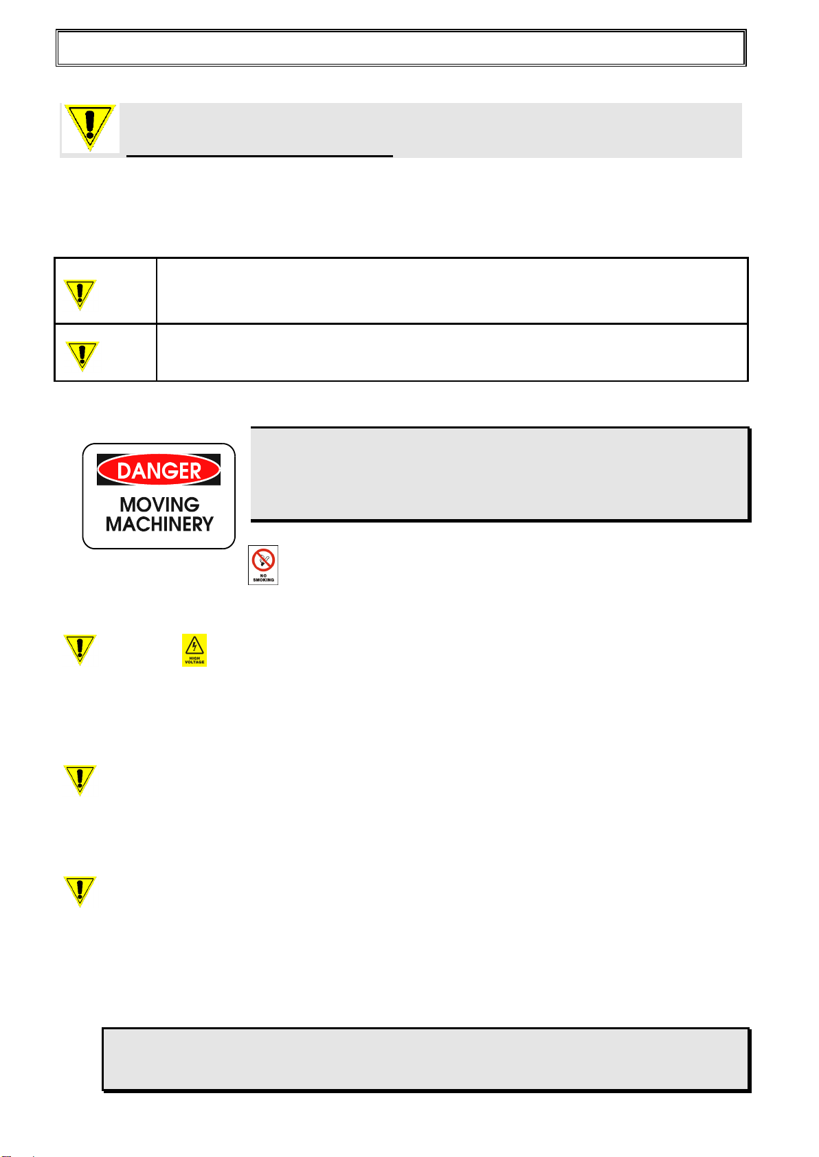
Important Notes
Do NOT remove access panels without isolating power.
Do NOT operate unit with access panels removed due to the
presence of rotating equipment.
All controls are 230/240V.
No Smoking
Heatcraft Australia recommends No Smoking within a distance of 15 metres of the unit.
Warning –Electrical Hazard
A qualified Electrician must carry out all electrical work. All field wiring must conform to the
requirements of the equipment and all applicable National and Local Codes.
Always isolate the power to the unit before checking and / or diagnosing the units. Never work
on any electrical item without isolating or disconnecting the power supply.
Caution –Unit Pressurized
All units are supplied pre-charged with the working refrigerant. Do not vent any refrigerant to
the atmosphere as this is illegal. If for any reason the unit needs to be altered engage the
services of a qualified refrigeration mechanic.
Caution –Refrigerant Type
All units are designed to work effectively with HFC refrigerants R134a (MT units from July
2011) & R404A (LT). Medium temp units made prior to July 2011 used R22 (HCFC)
refrigerant. Under no circumstances can a refrigerant such as Ammonia, Hydrocarbon, Water
or Glycol be used in this product. Do not change the refrigerant type as the performance of the
unit will be affected.
Refrigerant can be harmful if it is inhaled and/or makes contact with exposed skin.
Refrigerant must be used and recovered responsibly. Extreme care must be taken when
handling refrigerant, as personnel injury or death may occur.
Warning
This indicates contents for which, if disregarded, the possibility of human death
or severe injury can be assumed.
Caution
This indicates contents for which, if disregarded, the possibility of human injury
or the possibility of material damage can be assumed.
Manufactured for Heatcraft Australia Pty Ltd ACN 000 056 717 Document No.: CL276A.DOC
Page No. 4of 19
Caution –Lubricant Oil Type
All compressors are charged with PolyolEster (POE) oil. POE can be used with HCFC
refrigerants, such as R22 (s/seded MT units), and HFC refrigerants, such as R404A and R134a
(MT units from July 2011). Use ONLY POE oil, do NOT mix POE with other oils, when using
HFC refrigerants.
Caution –Sharp Edges
All units are manufactured with sheet metal and in this process all care is taken to ensure the
edges are concealed. Avoid contact with sheet-metal edges and the coil fins. They can be sharp
and are a potential personal injury hazard. Please take care when accessing in or around the
unit.
Warning –Qualified Personnel
All units may only be installed, commissioned, decommissioned and serviced by qualified and
trained personnel (refrigeration mechanics and/or electricians) who have sufficient knowledge
in this type of equipment. It is the purchaser’s responsibility to co-ordinate with qualified
personnel as required.
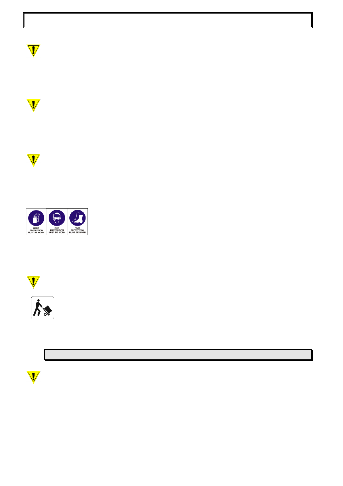
Personal Protective Equipment
Heatcraft Australia recommends as a secondary safety precaution that all personnel working
with the unit wear appropriate Personal Protective Equipment (PPE) such as gloves, eyewear
and footwear.
Caution –Lifting of Unit
Units are shipped in either timber crates or cardboard cartons depending on the size of the
unit. These units are generally considered to be heavy and may require special lifting
equipment. Units are fitted with either handles or eye bolts for lifting. Do not lift units by pipe work or
electrical cable etc. Refer to table 2 in General Outline Drawings for specific unit weights
Always take care to ensure a proper weight balance before lifting and moving unit.
Caution –High and Low Temperatures
Compressor housing and discharge line temperatures may reach 150°C due to failure of system
components. Wiring and other materials which could be damaged by these temperatures should
not come into contact with the housing or discharge line.
Moreover, even in normal working operation, the unit can generate very high (may exceed
100°C) and very low (below -40°C) temperatures on compressor housing and tubing surfaces
resulting in the possibilities of severe contact burns. Special caution must be taken when
working around the unit.

Manufactured for Heatcraft Australia Pty Ltd ACN 000 056 717 Document No.: CL276A.DOC
Page No. 5of 19
Caution –Motor Protection
WARNING: Do not insert any object into operating fans. Ignoring this warning may
result in personal injury and/or severe equipment damage and consequences.
Hermetic compressors, and external rotor motor fans, are fitted with inherent internal or
external line break motor protection. After opening, the protector may not reset for several
hours until the motor cools sufficiently. Do not assume that the motor has suffered an open
circuit failure without first allowing it to cool.
Caution –Internal Pressure Relief (IPR) Valve
Some hermetic compressors include an IPR valve. The IPR valve will open when the discharge
pressure exceeds the suction pressure by a certain value, which is set by the compressor
manufacturer. When it has opened, the compressor sump will become warm and the
compressor will trip out on the motor protector. The unit may take 2 to 3 hours to reset and
restart automatically if this happens. “AW” compressors have an IPR valve.
Do NOT assume that a compressor that is running, but not pumping, is faulty.
Stop the compressor and allow the pressures to balance, and then start the compressor
again.
Purpose
Kirby Drop-In units are standard OEM products of Heatcraft Australia including all “high”,
“medium” and “low” temperature application ranges. They are designed for continuously
supplying and receiving the refrigerant to and from the evaporator(s), and rejecting the heat
extracted from the cold space to surrounding atmosphere where the units are installed.
Kirby Drop-In units are intended for installing in a typical ventilated indoor or outdoor ( with
suitable covers) environment (Refer to the General Arrangement Drawing section for details)
with the ambient temperature between 10 and 43°C and compressor return vapour temperature
no greater than 20°C.
They are not intended for environments that may have harmful, corrosive or flammable
atmospheres. Marine environments are considered corrosive; please consult Heatcraft before
installing in this environment.
Standard Design Conditions
From July 2011, Medium / High temperature Kirby Drop-In units are designed for refrigerant
R134a, to be used in commercial cool room applications ranging from 0°C to +10°C saturated
suction. Previous models used R22 refrigerant, and those models MUST not be used with any
other refrigerant. The refrigerant used is CLEARLY marked on the unit serial plate.
Low temperature Kirby Drop-In units are designed, for primary refrigerant R404A, to be used
in commercial freezer room applications ranging from -35°C to -10°C saturated suction.
Please refer to sales data sheet CL247 for standard Kirby Drop-In unit configurations, options
offered and other detailed information such as capacity variations for other refrigerants.
For special design requirements (non standard conditions and/or refrigerants), please inquire with your
local representatives and/or Heatcraft Australia local branches, or call our national telephone number 13
23 50 for your nearest available information resources.

Manufactured for Heatcraft Australia Pty Ltd ACN 000 056 717 Document No.: CL276A.DOC
Page No. 6of 19
Installation Instructions
Kirby Drop-In Units are designed to be installed from the top of the cool/freezer room. As
such they should be inserted into the appropriate hole cut in the roof of the room. A roof gasket
is provided, to be used between the unit and the roof. Take care to install this gasket correctly
otherwise there will be excessive moisture ingress into the room causing reduced operating
efficiencies and increased running costs.
Unpacking of Unit
When unpacking, check for any damage to packing material or the unit itself which may affect
the unit’s performance. If any such damage is evident, please contact your local Heatcraft
branch.
When the unit has been removed from the packaging under no circumstances is the unit
allowed to rest on the evaporator drain tray/covers. Leave the unit on the supporting
packaging until ready to install.
Unpacking Timber Crate Units
To remove the unit from the timber crate proceed as follows
1. Remove the top of the timber crate
2. Attach the appropriate lifting equipment to the two (2) eye bolts located at either end of
the blue plastic plug.
3. Lift the unit straight up and position in the cool room. Do not allow the unit to rest on the
evaporator housing.
Unpacking Cardboard Carton Units
To remove the unit from the cardboard box proceed as follows
1. Open the top of the box
2. Lift the unit straight up using the two (2) handles provided, one at either end of the unit.
3. Position the unit in the cool room. Do not allow the unit to rest on the evaporator
housing.
Prior to installing the unit in the cool/freezer room ensure there is sufficient clearance
above the room to accommodate the full height of the unit. These units are intended to be
dropped-in to the cool room.
Installation Location (Refer to the General Arrangement Drawing section)
If the unit is to be located in close proximity to a wall or similar obstruction, the minimum
distance from the condenser coil face to the obstruction must be greater than 400 mm.
It is particularly important for the condensing unit section to allow sufficient
unobstructed air-discharge space around the unit to prevent warm air recirculation to
the condenser.
Coolroom units-
Coolroom units are induced draft discharging into the cooled space. The evaporator coil face
should be maintained at least 300mm from the nearest wall.
Evaporator section should be installed as far as possible from any room access door(s),
preferably discharging air towards the access door.
Cabinet Units-
Cabinet unit evaporators are forced draft discharge to the rear of the cabinet. The construction
of the unit prevents the evaporator from being installed too close to cabinet walls etc.

Manufactured for Heatcraft Australia Pty Ltd ACN 000 056 717 Document No.: CL276A.DOC
Page No. 7of 19
Electrical Connection
Kirby Drop-In units are supplied fitted with either a single phase or
three phase connecting plug. Single phase units may be fitted with
either a 10 Amp or a 15 Amp plug depending on the specific unit.
All three phase units are fitted with a 15 Amp three phase and neutral plug.
Pressure Settings
Kirby Drop-In units have a maximum operating pressure of 32 Bar(g) determined on
pressure vessels (such as liquid receivers). Pressure limiting device settings such as the
HP control must be 29 Bar(g) or lower in accordance with AS1677.2 that the pressure
limiting device setting is no greater than 0.9 times the maximum operating pressure.
In general, Heatcraft Australia sets the HP control to allow a maximum condensing
temperature of 60°C. The corresponding saturation pressures for the respective refrigerants
cut-out points for safety protection purpose are approximately 28 Bar(g) for R404A, 23 Bar(g)
for R22 (s/seded MT models), and 16 bar for R134a (MT models from July 2011).
Heatcraft Australia also recommends the LP switch to be used as a safety protection device.
Depending on the application and compressor, LP cut-in and differential points should be set
with the following considerations:
Set the cut-out points at 3–5 K below the respective minimum design saturated suction
temperatures (Refer to the Standard Design Conditions section for saturated suction
temperature ranges).
Set the differential to no more than 2 Bar.
The cut-out pressure shall be in the positive pressure region.
When the unit is installed in a cold ambient, the cut-out pressure shall be lower than the
pressure corresponding to the ambient temperature.
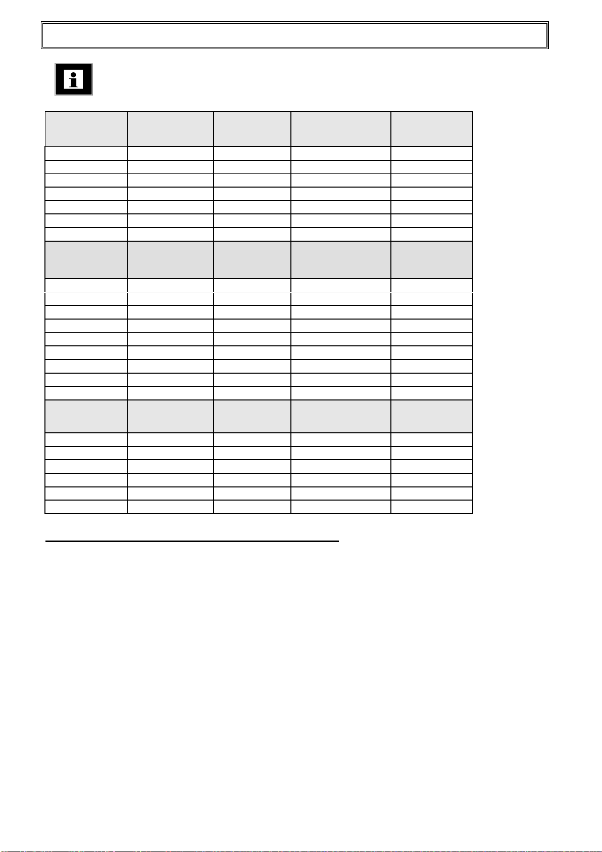
Dixell Control Settings
Dixell controls are supplied with factory default setting as listed in the Dixell instruction
manual, supplied with individual units. Heatcraft alters some of these setting as listed in the
table below.

Manufactured for Heatcraft Australia Pty Ltd ACN 000 056 717 Document No.: CL276A.DOC
Page No. 8of 19
TEMPERATURE
New R134a MT
Models from July
2011
Superseded R22
MT Models (prior to
July 2011)
CONTROL
SET POINT
(Cut In)
Cut
Out
DEFROST
TERMINATION
FANS
STOP
DEFROST
TIME
KPC800-6
KPC800-4
XR03CX
3° C
1° C
KPC1000-6
KPC1000-4
XR03CX
3° C
1° C
KPC1200-4
XR03CX
3° C
1° C
KPC1400-6
KPC1400-4
XR03CX
3° C
1° C
KPC1700-6
KPC1700-4
XR03CX
3° C
1° C
KSC1800-4
XW60K
3° C
1° C
KSC2000-6
KSC2000-4
XW60K
3° C
1° C
KSC2700-6
KSC2900-4
XW60K
3° C
1° C
KSC3500-6
KSC4100-4
XW60K
3° C
1° C
LT R404A models
KPF1000-4
XW60K
-15° C
-17° C
2° C
11° C
20 MIN
KPF1200-4
XW60K
-15° C
-17° C
2° C
11° C
20 MIN
KSF1500-4
XW60K
-15° C
-17° C
2° C
11° C
20 MIN
KSF2000-4
XW60K
-15° C
-17° C
2° C
11° C
20 MIN
KSFT2600-4
XW60K
-15° C
-17° C
2° C
11° C
20 MIN
Table 1. Dixell Control Setting
General Commissioning & Decommissioning Guide
Warning –Commissioning
Medium Temp Units from July 2011 use R134a refrigerant, with TX valve refrigerant control.
Variation of TX valve setting from factory set up is possible. Changes should ONLY be made
by a qualified refrigeration mechanic.
LT units use Capillary refrigerant control and cannot be altered from factory set up.
During commissioning please check the following for correct operation
Compressors starting and stopping –the compressor should start quickly and take no
than 0.5 second to achieve running speed. If the start is slow and the compressor
sounds to be “labouring” or the relay “chatters” please investigate to determine the
problem. On stopping, the compressor should stop within 1 second, without any
knocking noises.
Temperature Setting –check the unit is cycling on and off as expected.
Water Drains –check to ensure that water is draining away correctly. A “P” trap should
be installed in the drain tube on the outside of the room.
TX valve and bulb (R134a medium temp units from July 2011)- ensure the TX valve
insulation is firmly in place (KPC models), and the sensor bulb is firmly in place on the
suction line (all R134a MT models).
TX valve setting (R134a medium temp units from July 2011)- Superheat setting is
factory set at 4K in normal operating condition (+2°C air on). Some adjustment may be
necessary depending on the conditions during initial pulldown of the space. Always
return to 4K for normal operation.
Defrost Heater (LT Units) –manually activate the defrost cycle to make sure the
heaters are working correctly.

Manufactured for Heatcraft Australia Pty Ltd ACN 000 056 717 Document No.: CL276A.DOC
Page No. 9of 19
Warning –Decommissioning
If the unit should need to be decommissioned please proceed as follows
Remove the unit from the room.
Have the refrigerant removed from the unit by a licensed refrigeration mechanic.
Dispose of the unit in an appropriate recycling centre.
Material Safety Data Sheets –M.S.D.S.
These are available from your nearest Heatcraft Branch for all refrigerants that Kirby Drop-In
units are approved for, and for oils and other materials as needed.
Important Notes
To ensure Kirby Drop-In units operate efficiently and for a long working life, always obtain
genuine replacement parts from your local Heatcraft Wholesale Branch. Genuine replacement
parts are covered by the warranty. Refer to the Standard Terms & Conditions of Sale in the
Price Guide for warranty statements.
Continuous product improvement is our company policy. Heatcraft Australia reserves the right
to make changes in product specifications and/or this instruction manual without notice.
Heatcraft Australia is dedicated to providing safe products and protecting the environment by complying
with all applicable national laws and regulations governing environmental protection. New and used
refrigerants cannot be vented into atmosphere. Reclaim all used refrigerants. EPA regulations are
constantly updated. Ensure your refrigerant handling procedure complies with the relevant regulations.
Manufactured for Heatcraft Australia Pty Ltd ACN 000 056 717 Document No.: CL276A.DOC
Page No. 10 of 19
General Schematic Drawing & Outline Drawings
New R134a MT
Models from July
2011
Schematic
Outline
Hole Size
Unit Weight
W x D
Kg
KPC800-6
MS793-8
SK696-2
825X435
31
KPC1000-6
MS793-8
SK696-4
1040X435
33
KPC1400-6
MS793-9
SK696-4
1045X435
50
KPC1700-6
MS793-9
SK696-4
1045X435
58
KSC2000-6
MS793-10
SK696-9
660X550
90
KSC2700-6
MS793-10
SK696-10
1085X665
128
KSC3500-6
MS793-10
SK696-11
1085X665
135
Superseded R22
MT Models (prior to
July 2011)
Schematic
Outline
Hole Size
W x D
Unit Weight
Kg
KPC800-4
MS793-6
SK696-2
825X435
33
KPC1000-4
MS793-6
SK696-2
825X435
33
KPC1200-4
MS793-6
SK696-4
1045X435
46
KPC1400-4
MS793-7
SK696-4
1045X435
50
KPC1700-4
MS793-7
SK696-4
1045X435
58
KSC1800-4
MS793-1
SK696-8
660X550
88
KSC2000-4
MS793-2
SK696-9
660X550
90
KSC2900-4
MS793-2
SK696-10
1085X665
128
KSC4100-4
MS793-2
SK696-11
1085X665
135
LT R404A
Models
Schematic
Outline
Hole Size
W x D
Unit Weight
Kg
KPF1000-4
MS793-4
SK696-13
1045X435
64
KPF1200-4
MS793-4
SK696-13
1045X435
68
KSF1500-4
MS793-4
SK696-9
660X550
92
KSF2000-4
MS793-4
SK696-10
1085X665
135
KSFT2600-4
MS793-5
SK696-18
1085X665
155
Table 2 - Electrical Schematics and General Information
Manufactured for Heatcraft Australia Pty Ltd ACN 000 056 717 Document No.: CL276A.DOC
Page No. 11 of 19
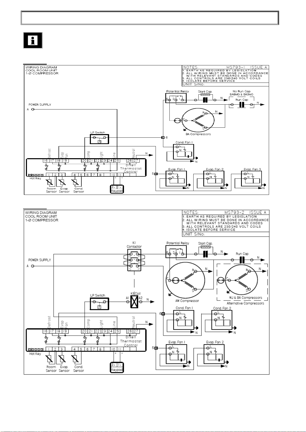
Schematic Drawings
MS793-1
MS793-2

Manufactured for Heatcraft Australia Pty Ltd ACN 000 056 717 Document No.: CL276A.DOC
Page No. 12 of 19
MS793-4
MS793-5

Manufactured for Heatcraft Australia Pty Ltd ACN 000 056 717 Document No.: CL276A.DOC
Page No. 13 of 19
MS793-6
MS793-7
MS793-8

Manufactured for Heatcraft Australia Pty Ltd ACN 000 056 717 Document No.: CL276A.DOC
Page No. 14 of 19
MS793-9
MS793-10

Manufactured for Heatcraft Australia Pty Ltd ACN 000 056 717 Document No.: CL276A.DOC
Page No. 15 of 19
General Outline Drawing
SK696-2
SK696-4

Manufactured for Heatcraft Australia Pty Ltd ACN 000 056 717 Document No.: CL276A.DOC
Page No. 16 of 19
SK696-8
SK696-9

Manufactured for Heatcraft Australia Pty Ltd ACN 000 056 717 Document No.: CL276A.DOC
Page No. 17 of 19
SK696-10
SK696-11

Manufactured for Heatcraft Australia Pty Ltd ACN 000 056 717 Document No.: CL276A.DOC
Page No. 18 of 19
SK696-13
SK696-18

Manufactured for Heatcraft Australia Pty Ltd ACN 000 056 717 Document No.: CL276A.DOC
Page No. 19 of 19
COMMISSIONING NOTES
Table of contents
Other Heatcraft Industrial Equipment manuals


