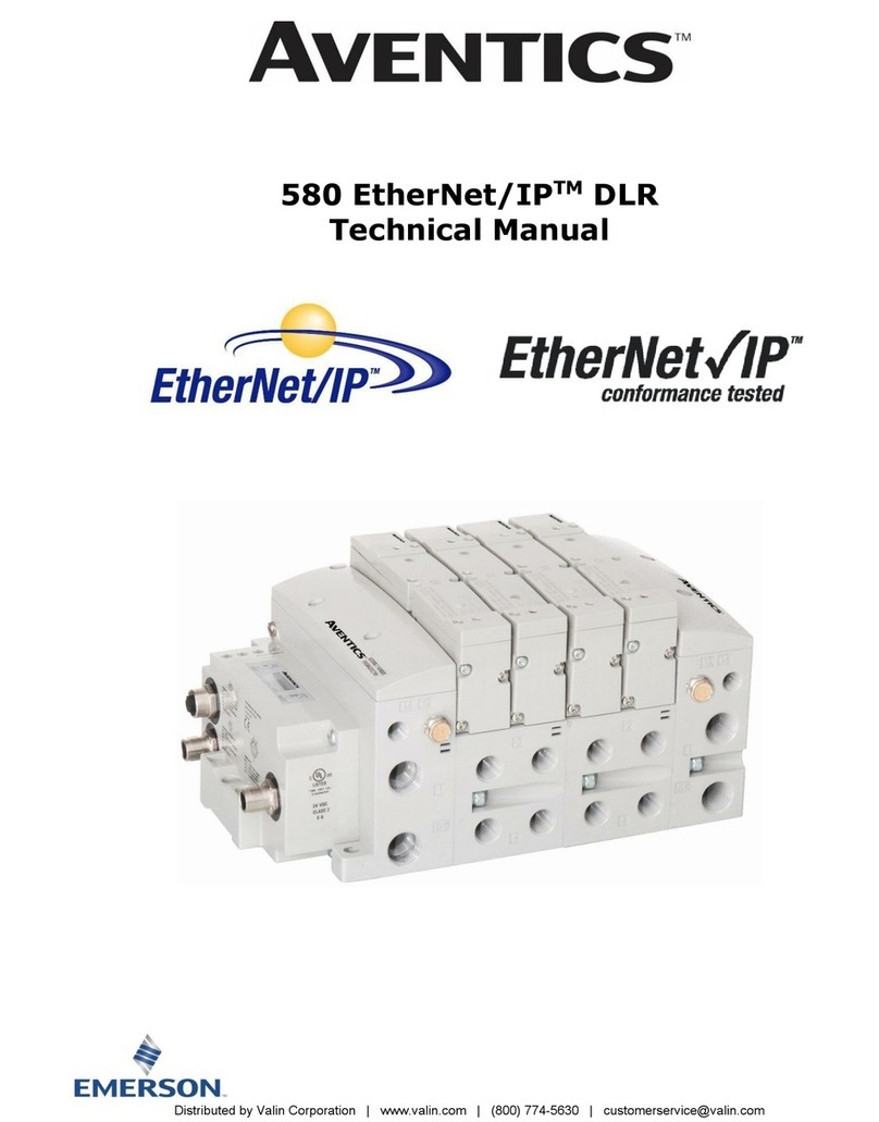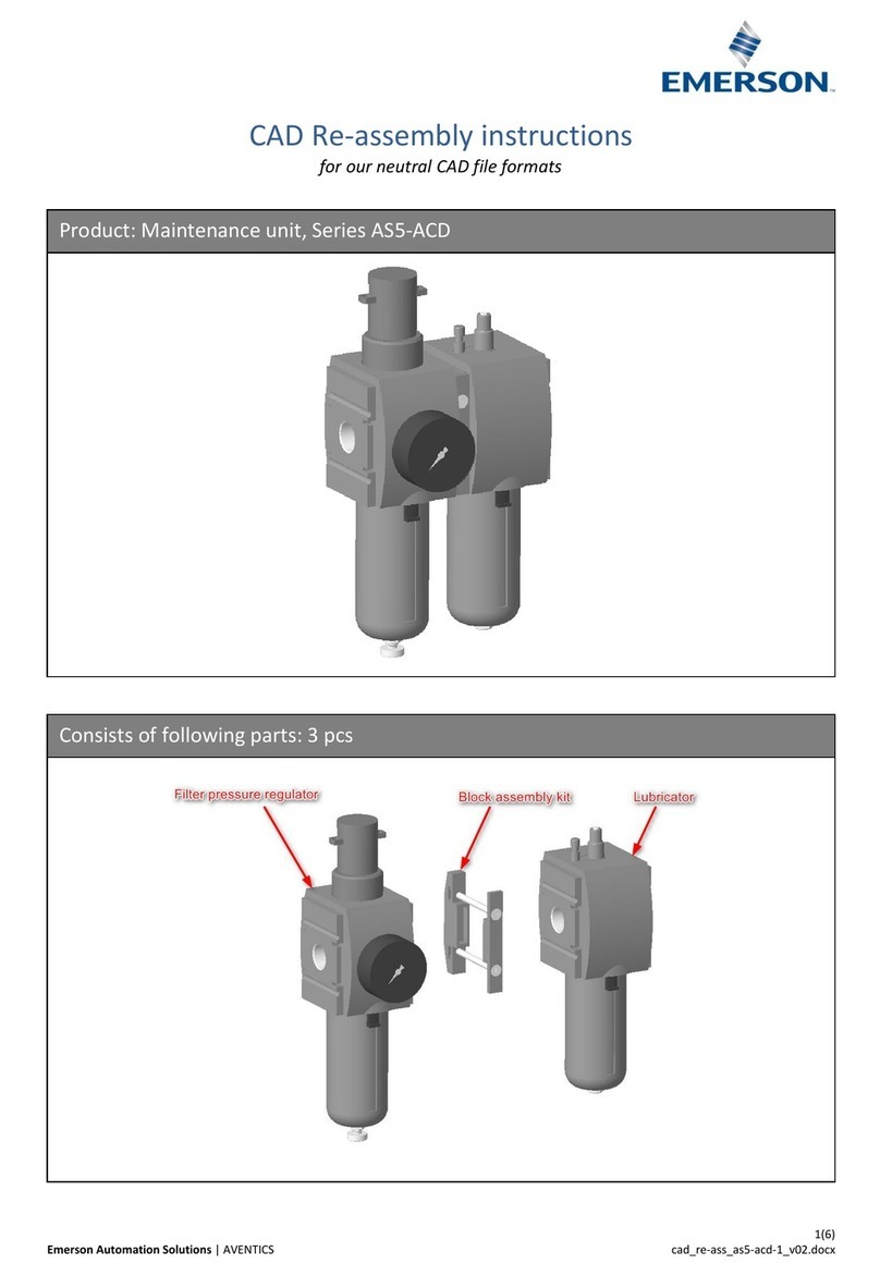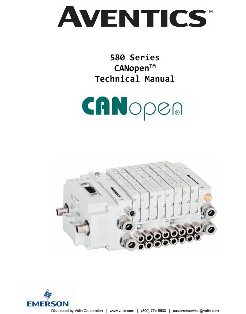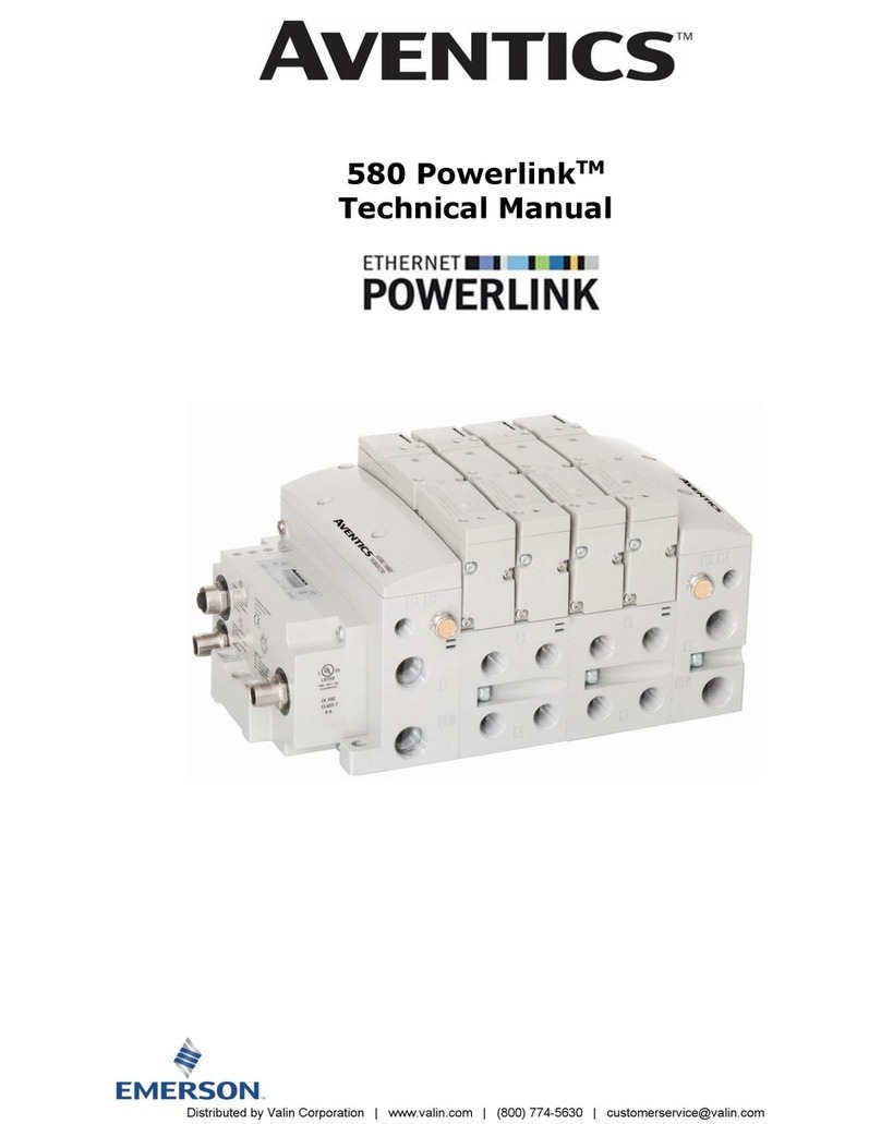
580 IO-LinkTM Technical Manual
Page 4
TD580IOLTM1-9EN 5/23
Subject to change without notice
www.emerson.com
Table of Contents
PAGE
1. About IO-LinkTM ................................................................................................................................................. 5
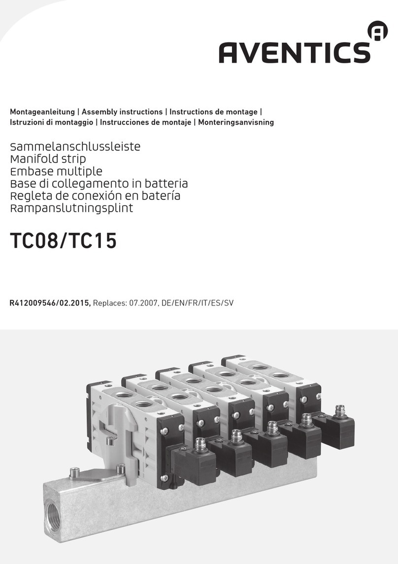
2. 580 Introduction................................................................................................................................................. 5
2.1 Pneumatic Valve Manifold –501 Series shown.......................................................................................... 6
2.2 Manifold Connectors.............................................................................................................................. 7
2.3 Z-Board™Connectors ........................................................................................................................... 8
2.4 2035 Series Pneumatic Valve Manifold..................................................................................................... 9
2.5 2035 Series Z-Board™Connectors.........................................................................................................10
3. IO-LinkTM Communication Module........................................................................................................................11
3.1 Connector Pin-Outs ..............................................................................................................................12
3.2 Chassis Ground ...................................................................................................................................13
3.3 Power Consumption .............................................................................................................................14
3.4 Recommended External Fuses ...............................................................................................................15
3.5 Diagnostics –LED Functions..................................................................................................................16
3.6 Diagnostic I/O Data .............................................................................................................................17
3.7 Diagnostic Events ................................................................................................................................18
3.8 ISDU Object Data ................................................................................................................................19
3.8.1 General (IO-Link Predefined) Device Parameters......................................................................................19
3.8.2 Product-specific ISDU...........................................................................................................................20
3.8.3 Event Data..........................................................................................................................................23
4. I/O Mapping Examples .......................................................................................................................................24
4.1 Coil Output Mapping –500 Series ..........................................................................................................24
4.2 Coil Status Mapping –500 Series...........................................................................................................24
4.3 Coil Output Mapping –2035 Series ........................................................................................................25
4.4 Coil Status Mapping –2035 Series .........................................................................................................25
5. Configuration Example - Balluff Master .................................................................................................................26
5.1 Connect the Aventics 580 IO-LinkTM manifold...........................................................................................26
5.2 Controller Tags (RSLogix 5000) .............................................................................................................27
5.3 Configure Port for IO-LinkTM ..................................................................................................................28
5.4 Enable valve power ..............................................................................................................................29
5.5 Control valve coil outputs .....................................................................................................................30
6. Configuration Example - IFM Master.....................................................................................................................31
6.1 Connect the Aventics 580 IO-LinkTM manifold...........................................................................................31
6.2 Controller tags (RSLogix 5000)..............................................................................................................32
6.3 Configure port for IO-LinkTM ..................................................................................................................33
6.4 Control valve coil outputs .....................................................................................................................34
7. Configuration Example - Siemens Master..............................................................................................................35
7.1 Connect the Aventics 580 IO-LinkTM manifold...........................................................................................35
7.2 Create the PLC hardware configuration for the Siemens ET200 IO Link master. ...........................................36
7.3 Install the Aventics 580 IO-LinkTM IODD file. ...........................................................................................39
8. Configuration Example - Rockwell Master..............................................................................................................44
8.1 Connect the Aventics 580 IO-LinkTM manifold...........................................................................................44
8.2 Create the PLC hardware configuration for the Rockwell 1732E-8IOLM12R IO LinkTM master..........................45
9. Appendix ..........................................................................................................................................................48
9.1 System Specifications...........................................................................................................................48
9.2 Troubleshooting Communication Node ....................................................................................................48
9.3 Technical Support ................................................................................................................................48
Distributed
by
Valin
Corporation
|
www.valin.com
|
(800)
774-5630
|
[email protected]