NEXCOBOT NEX 812 User manual

NexCOBOT Co., Ltd.
NexCOBOT Co., Ltd.
Published October 2020 www.nexcobot.com
Intelligent Platform & Services Business Unit
Embedded Computing (Industrial Motherboard)
NEX 812
User Manual

Copyright © 2020 NexCOBOT Co., Ltd. All Rights Reserved. ii NEX 812 User Manual
Contents
Contents
Preface
Copyright ............................................................................................. iv
Disclaimer.............................................................................................. iv
Acknowledgements ............................................................................... iv
Regulatory Compliance Statements........................................................ iv
Declaration of Conformity...................................................................... iv
RoHS Compliance ................................................................................... v
Warranty and RMA ................................................................................ vi
Safety Information ................................................................................viii
Installation Recommendations...............................................................viii
Safety Precautions.................................................................................. ix
Technical Support and Assistance............................................................ x
Conventions Used in this Manual............................................................ x
Global Service Contact Information........................................................ xi
Package Contents..................................................................................xii
Ordering Information ............................................................................xiii
Chapter 1: Product Introduction
Overview ................................................................................................1
Key Features ...........................................................................................1
Hardware Specifications..........................................................................2
Knowing Your NEX 812 ..........................................................................4
Edge I/O View......................................................................................5
Chapter 2: Jumpers and Connectors
Before You Begin ....................................................................................6
Precautions ............................................................................................6
Jumper Settings ......................................................................................7
Locations of the Jumpers and Connectors...............................................8
Jumpers..................................................................................................9
CMOS Clear Selection .........................................................................9
Chassis Intrusion..................................................................................9
Connector Pin Definitions .....................................................................10
24-pin ATX Power Connector ............................................................10
8-pin ATX Power Connector ..............................................................10
TPM Header ......................................................................................11
CPU Fan Connector...........................................................................11
Chassis Fan Connectors.....................................................................12
BIOS Programmable Connector .........................................................12
System Panel Connector....................................................................13
Digital I/O Connector.........................................................................13
COM2 to COM6 Internal Serial Port Connectors ................................14
Serial ATA 6.0Gb/s Connector 1.........................................................14
Serial ATA 6.0Gb/s Connector 2.........................................................15
Serial ATA 6.0Gb/s Connector 3.........................................................15
Serial ATA 6.0Gb/s Connector 4.........................................................16
Serial ATA 6.0Gb/s Connector 5.........................................................16
Serial ATA 6.0Gb/s Connector 6.........................................................17
USB 2.0 Connector............................................................................17

Copyright © 2020 NexCOBOT Co., Ltd. All Rights Reserved. iii NEX 812 User Manual
Contents
USB 2.0 Connector............................................................................18
Speaker-out Connector......................................................................18
Block Diagram .................................................................................19
Chapter 3: BIOS Setup
About BIOS Setup.................................................................................20
When to Configure the BIOS.................................................................20
Default Configuration...........................................................................21
Entering Setup......................................................................................21
Legends................................................................................................21
BIOS Setup Utility..................................................................................23
Main .................................................................................................23
Advanced..........................................................................................24
Chipset..............................................................................................35
Security .............................................................................................37
Boot..................................................................................................38
Save & Exit ........................................................................................38

Copyright © 2020 NexCOBOT Co., Ltd. All Rights Reserved. iv NEX 812 User Manual
Preface
PrefaCe
Copyright
This publication, including all photographs, illustrations and software, is
protected under international copyright laws, with all rights reserved. No
part of this manual may be reproduced, copied, translated or transmitted in
any form or by any means without the prior written consent from Nexcobot
Co., Ltd.
Disclaimer
The information in this document is subject to change without prior notice
and does not represent commitment from Nexcobot Co., Ltd. However, users
may update their knowledge of any product in use by constantly checking its
manual posted on our website: http://www.nexcobot.com. NexCOBOT shall
not be liable for direct, indirect, special, incidental, or consequential damages
arising out of the use of any product, nor for any infringements upon the rights
of third parties, which may result from such use. Any implied warranties of
merchantability or fitness for any particular purpose is also disclaimed.
Acknowledgements
NEX 812 is a trademark of Nexcobot Co., Ltd. All other product names
mentioned herein are registered trademarks of their respective owners.
Regulatory Compliance Statements
This section provides the FCC compliance statement for Class A devices and
describes how to keep the system CE compliant.
Declaration of Conformity
FCC
This equipment has been tested and verified to comply with the limits for
a Class A digital device, pursuant to Part 15 of FCC Rules. These limits are
designed to provide reasonable protection against harmful interference when
the equipment is operated in a commercial environment. This equipment
generates, uses, and can radiate radio frequency energy and, if not installed
and used in accordance with the instructions, may cause harmful interference
to radio communications. Operation of this equipment in a residential area
(domestic environment) is likely to cause harmful interference, in which
case the user will be required to correct the interference (take adequate
measures) at their own expense.
CE
The product(s) described in this manual complies with all applicable
European Union (CE) directives if it has a CE marking. For computer systems
to remain CE compliant, only CE-compliant parts may be used. Maintaining
CE compliance also requires proper cable and cabling techniques.
Copyright © 2020 NexCOBOT Co., Ltd. All Rights Reserved. vNEX 812 User Manual
Preface
RoHS Compliance
NexCOBOT RoHS Environmental Policy and
Status Update
NexCOBOT is a global citizen for building the digital
infrastructure. We are committed to providing green
products and services, which are compliant with
European Union RoHS (Restriction on Use of Hazardous Substance in
Electronic Equipment) directive 2011/65/EU, to be your trusted green
partner and to protect our environment.
RoHS restricts the use of Lead (Pb) < 0.1% or 1,000ppm, Mercury (Hg)
< 0.1% or 1,000ppm, Cadmium (Cd) < 0.01% or 100ppm, Hexavalent
Chromium (Cr6+) < 0.1% or 1,000ppm, Polybrominated biphenyls (PBB) <
0.1% or 1,000ppm, and Polybrominated diphenyl Ethers (PBDE) < 0.1% or
1,000ppm.
In order to meet the RoHS compliant directives, NexCOBOT has established an
engineering and manufacturing task force in to implement the introduction
of green products. The task force will ensure that we follow the standard
NexCOBOT development procedure and that all the new RoHS components
and new manufacturing processes maintain the highest industry quality
levels for which NexCOBOT are renowned.
The model selection criteria will be based on market demand. Vendors and
suppliers will ensure that all designed components will be RoHS compliant.
How to recognize NexCOBOT RoHS Products?
For existing products where there are non-RoHS and RoHS versions, the
suffix “(LF)” will be added to the compliant product name.
All new product models launched after January 2013 will be RoHS compliant.
They will use the usual NexCOBOT naming convention.

Copyright © 2020 NexCOBOT Co., Ltd. All Rights Reserved. vi NEX 812 User Manual
Preface
Warranty and RMA
NexCOBOT Warranty Period
NexCOBOT manufactures products that are new or equivalent to new in
accordance with industry standard. NexCOBOT warrants that products will
be free from defect in material and workmanship for 2 years, beginning on
the date of invoice by NexCOBOT.
NexCOBOT Return Merchandise Authorization (RMA)
▪Customers shall enclose the “NexCOBOT RMA Service Form” with the
returned packages.
▪Customers must collect all the information about the problems
encountered and note anything abnormal or, print out any on-screen
messages, and describe the problems on the “NexCOBOT RMA Service
Form” for the RMA number apply process.
▪Customers can send back the faulty products with or without accessories
(manuals, cable, etc.) and any components from the card, such as CPU and
RAM. If the components were suspected as part of the problems, please
note clearly which components are included. Otherwise, NexCOBOT is
not responsible for the devices/parts.
▪Customers are responsible for the safe packaging of defective products,
making sure it is durable enough to be resistant against further damage
and deterioration during transportation. In case of damages occurred
during transportation, the repair is treated as “Out of Warranty.”
▪Any products returned by NexCOBOT to other locations besides the
customers’ site will bear an extra charge and will be billed to the customer.
Repair Service Charges for Out-of-Warranty Products
NexCOBOT will charge for out-of-warranty products in two categories, one
is basic diagnostic fee and another is component (product) fee.
System Level
▪Component fee: NexCOBOT will only charge for main components such
as SMD chip, BGA chip, etc. Passive components will be repaired for free,
ex: resistor, capacitor.
▪Items will be replaced with NexCOBOT products if the original one cannot
be repaired. Ex: motherboard, power supply, etc.
▪Replace with 3rd party products if needed.
▪If RMA goods can not be repaired, NexCOBOT will return it to the
customer without any charge.
Board Level
▪Component fee: NexCOBOT will only charge for main components, such
as SMD chip, BGA chip, etc. Passive components will be repaired for free,
ex: resistors, capacitors.
▪If RMA goods can not be repaired, NexCOBOT will return it to the
customer without any charge.

Copyright © 2020 NexCOBOT Co., Ltd. All Rights Reserved. vii NEX 812 User Manual
Preface
Warnings
Read and adhere to all warnings, cautions, and notices in this guide and
the documentation supplied with the chassis, power supply, and accessory
modules. If the instructions for the chassis and power supply are inconsistent
with these instructions or the instructions for accessory modules, contact
the supplier to find out how you can ensure that your computer meets
safety and regulatory requirements.
Cautions
Electrostatic discharge (ESD) can damage system components. Do the
described procedures only at an ESD workstation. If no such station is
available, you can provide some ESD protection by wearing an antistatic
wrist strap and attaching it to a metal part of the computer chassis.

Copyright © 2020 NexCOBOT Co., Ltd. All Rights Reserved. viii NEX 812 User Manual
Preface
Installation Recommendations
Ensure you have a stable, clean working environment. Dust and dirt can get
into components and cause a malfunction. Use containers to keep small
components separated.
Adequate lighting and proper tools can prevent you from accidentally
damaging the internal components. Most of the procedures that follow
require only a few simple tools, including the following:
▪A Philips screwdriver
▪A flat-tipped screwdriver
▪A grounding strap
▪An anti-static pad
Using your fingers can disconnect most of the connections. It is recommended
that you do not use needle-nose pliers to disconnect connections as these
can damage the soft metal or plastic parts of the connectors.
Safety Information
Before installing and using the device, note the following precautions:
▪Read all instructions carefully.
▪Do not place the unit on an unstable surface, cart, or stand.
▪Follow all warnings and cautions in this manual.
▪When replacing parts, ensure that your service technician uses parts
specified by the manufacturer.
▪Avoid using the system near water, in direct sunlight, or near a heating
device.
▪The load of the system unit does not solely rely for support from the
rackmounts located on the sides. Firm support from the bottom is highly
necessary in order to provide balance stability.
▪The computer is provided with a battery-powered real-time clock circuit.
There is a danger of explosion if battery is incorrectly replaced. Replace
only with the same or equivalent type recommended by the manufacturer.
Discard used batteries according to the manufacturer’s instructions.
Copyright © 2020 NexCOBOT Co., Ltd. All Rights Reserved. ix NEX 812 User Manual
Preface
Safety Precautions
1. Read these safety instructions carefully.
2. Keep this User Manual for later reference.
3. Disconnect the equipment from any AC outlet before cleaning or installing
a component inside the chassis. Use a damp cloth. Do not use liquid or
spray detergents for cleaning.
4. To prevent electrostatic build-up, leave the board in its anti-static bag
until you are ready to install it.
5. For plug-in equipment, the power outlet socket must be located near the
equipment and must be easily accessible.
6. Keep the board away from humidity.
7. Put the board on a stable surface. Dropping it or letting it fall may cause
damage.
8. Wear anti-static wrist strap.
9. Do all preparation work on a static-free surface.
10. Make sure the voltage of the power source is correct before
connecting the equipment to the power outlet.
11. Hold the board only by its edges. Be careful not to touch any of the
components, contacts or connections.
12. All cautions and warnings on the board should be noted.
13. Use the correct mounting screws and do not over tighten the screws.
14. Keep the original packaging and the anti-static bag; in case the board
has to be returned for repair or replacement.
Copyright © 2020 NexCOBOT Co., Ltd. All Rights Reserved. xNEX 812 User Manual
Preface
Technical Support and Assistance
1. For the most updated information of NexCOBOT products, visit
NexCOBOT’s website at www.nexcobot.com.
2. For technical issues that require contacting our technical support team or
sales representative, please have the following information ready before
calling:
– Product name and serial number
– Detailed information of the peripheral devices
– Detailed information of the installed software (operating system,
version, application software, etc.)
– A complete description of the problem
– The exact wordings of the error messages
Warning!
1. Handling the unit: carry the unit with both hands and handle it with care.
2. Maintenance: to keep the unit clean, use only approved cleaning products
or clean with a dry cloth.
Conventions Used in this Manual
Warning:
Information about certain situations, which if not observed,
can cause personal injury. This will prevent injury to yourself
when performing a task.
CAUTION!
CAUTION!CAUTION! Caution:
Information to avoid damaging components or losing data.
Note:
Provides additional information to complete a task easily.

Copyright © 2020 NexCOBOT Co., Ltd. All Rights Reserved. xi NEX 812 User Manual
Preface
Global Service Contact Information
Asia
Taiwan
NexCOBOT Taiwan
13F, No.916, Chung-Cheng Rd.,
ZhongHe District,
New Taipei City, 23586, Taiwan, R.O.C.
Tel: +886-2-8226-7796
Fax: +886-2-8226-7792
Email: [email protected]
www.nexcobot.com.tw
America
USA
NexCOBOT USA
2883 Bayview Drive,
Fremont CA 94538, USA
Tel: +1-510-362-0800
Email: [email protected]
www.nexcobot.com.cn
China
NexCOBOT China
Room 501, Building 1, Haichuang Building,
No.7 Qingyi Rd., Guicheng Street,
Nanhai District, Foshan City,
Guangdong Province, 528314, China
Tel: +86-757-8625-7118
www.nexcobot.com.cn
Copyright © 2020 NexCOBOT Co., Ltd. All Rights Reserved. xii NEX 812 User Manual
Preface
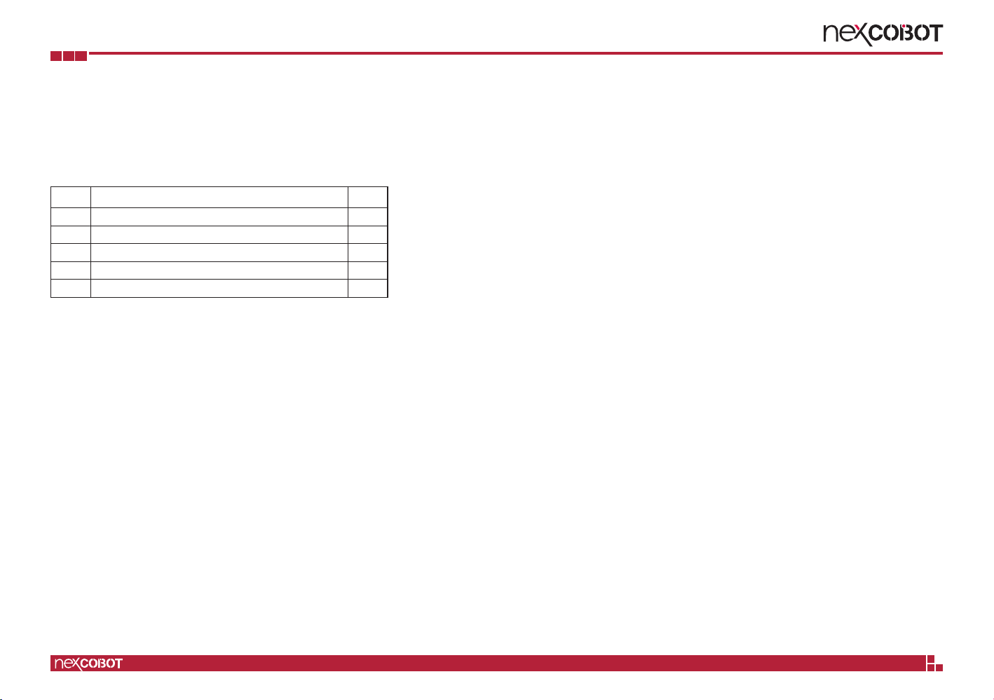
Package Contents
Before continuing, verify that the NEX 812 package that you received is
complete. Your package should have all the items listed in the following table.
Item Name Qty
1 NEX 812 Motherboard 1
2 SATA Cable 1
3COM Port Cable 1
4 I/O Shield 1
5Driver CD 1

Copyright © 2020 NexCOBOT Co., Ltd. All Rights Reserved. xiii NEX 812 User Manual
Preface
Ordering Information
The following information below provides ordering information for NEX 812.
NEX 812 (P/N: 6879G0008120F)
Micro-ATX Form Factor, 6th/7th Generation Intel®Core™ LGA1151
Processor, Q170, LGA1151, DDR4 x4 up to 64GB, 2 x HDMI, 1 x DVI-I, 10 x
USB 3.0, 4 x USB 2.0, 2 x GbE, 6 x SATAIII, 5 x RS232, 1 x RS232/422/485,
1 x PCIe x16, 1 x PCIe x4, 1 x PCI
Copyright © 2020 NexCOBOT Co., Ltd. All Rights Reserved. 1NEX 812 User Manual
Chapter 1: Product Introduction
ChaPter 1: ProduCt IntroduCtIon
Key Features
▪7th/6th Generation Intel®Core™ i7/i5/i3/Pentium®/Celeron®processors,
14nm, LGA1151 socket, PCH Q170
▪4 x U-DIMM DDR4 with ECC or non-ECC SO-DIMM 2133/1867MHz, up
to 64GB
▪Support Multi Display DVI-I+HDMI, HDMI+HDMI
▪2 x Intel®GbE LAN ports, 10 x USB 3.0, 4 x USB 2.0, 5 x RS232,
1 x RS232/485/422, 6 x SATAIII, HD Audio
▪1 x PCIe x16, 1 x PCIe x4, 1 x PCIe x1, 1 x PCI
▪8 Bit DIO, TPM (optional)
Overview

Copyright © 2020 NexCOBOT Co., Ltd. All Rights Reserved. 2NEX 812 User Manual
Chapter 1: Product Introduction
Hardware Specifications
CPU Support
▪6th/7th Generation Intel®Core™ Processors, socket LGA1151
Chipset
▪Intel®Q170 Express Chipset
Main Memory
▪4 x DDR4 U-DIMM memory sockets with non-ECC support, up to 64 GB
2133/1876MHz
BIOS
▪AMI (UEFI)
Display
▪Integrated Intel®Graphics
– 1 x DVI-I connector (resolution up to 1920 x 1080 @ 60Hz)
– VGA (resolution up to 1920 x 1080 @ 60Hz)
▪1 x HDMI1.4 connector (resolution up to 4096 x 2304 @ 30MHz)
System
▪1 x PS/2 connector, 10 x USB 3.0, 4 x USB 2.0
▪5 x RS232, 1 x RS232/485/422 & supports 5/12V on RI pin (COM1)
▪Realtek ALC887 5.1 Channel HDA codec, Internal SPKR
▪1 x Front panel header, 8-bit digital I/O (programmable input/output), WDT
▪Supports onboard TPM (optional)
▪3 x Smart fan connectors
Storage
▪6 x SATA III (6.0Gb/s) ports, support RAID 0/1/5/10
Expansion Slots
▪1 x PCIe 3.0/2.0 [x16], 1 x PCIe 3.0/2.0 [x4] Slot (open edge), 1 x PCIe
3.0/2.0 [x1] Slot (open edge), 1 x PCI
Rear I/O
▪1 x PS/2 combo port (keyboard and mouse support)
▪10 x USB 3.0, 2 x USB 2.0
▪1 x DVI-I, 2 x HDMI
▪1 x COM (COM1)
▪2 x RJ45:
– LAN 1: Intel®PHY i219LM GbE LAN (supports iAMT 11.0)
– LAN 2: Intel®i211AT GbE LAN
▪1 x HD Audio connector (1 x line-out + mic + line-in 3.5mm jack)
Internal I/O
▪4 x USB 2.0
▪5 x RS232
▪HD Audio:
– 1 x Audio pin header (speaker header x 1 [line-out])
Power Requirement
▪1 x 24-pin ATX power connector
▪1 x 8-pin (2x4) ATX 12V power connector

Copyright © 2020 NexCOBOT Co., Ltd. All Rights Reserved. 3NEX 812 User Manual
Chapter 1: Product Introduction
Dimensions
▪Micro-ATX form factor
▪Dimension: 244mm (L) x 244mm (W) (9.6” x 9.6”)
Environment
▪Board level operating temperature: 0ºC to 60ºC
▪Storage temperature: -40ºC to 85ºC
▪Relative humidity:
– 10% to 95% (operating, non-condensing)
– 5% to 95% (non-operating, non-condensing)
Certifications
▪Meet CE/FCC Class A

Copyright © 2020 NexCOBOT Co., Ltd. All Rights Reserved. 4NEX 812 User Manual
Chapter 1: Product Introduction
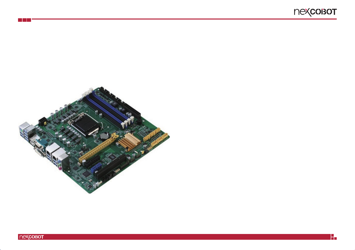
Knowing Your NEX 812
COM2
COM3 COM4 COM6COM5
DI/DO
Speaker-out
System Front Panel
USB 2.0
TPM Header
PCIPCIe x1
PCIe x4
PCIe x16
4 x SATAIII
Clear CMOS
ATX Power
Chassis Intrusion
BIOS Programmable
Chassis Fan 2
Chassis Fan 1
CPU FAN
DIMM A1 (DDR4)
DIMM A2 (DDR4)
DIMM B1 (DDR4)
DIMM B2 (DDR4)
ATX 12V
Copyright © 2020 NexCOBOT Co., Ltd. All Rights Reserved. 5NEX 812 User Manual
Chapter 1: Product Introduction
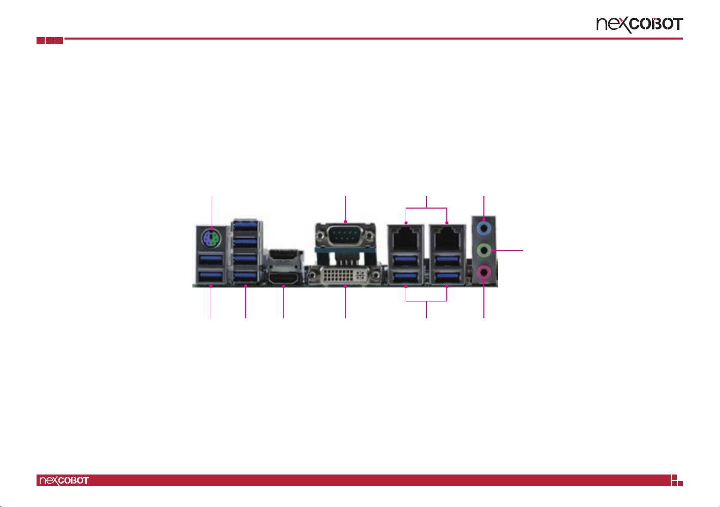
Edge I/O View
LAN
Mic-in
Line-in
Line-out
USB 3.0 USB 3.0 USB 3.0HDMI DVI-I
COMPS/2 Combo

Copyright © 2020 NexCOBOT Co., Ltd. All Rights Reserved. 6NEX 812 User Manual
Chapter 2: Jumpers and Connectors
ChaPter 2: JumPers and ConneCtors
This chapter describes how to set the jumpers and connectors on the
NEX 812 motherboard.
Before You Begin
▪Ensure you have a stable, clean working environment. Dust and dirt can
get into components and cause a malfunction. Use containers to keep
small components separated.
▪Adequate lighting and proper tools can prevent you from accidentally
damaging the internal components. Most of the procedures that follow
require only a few simple tools, including the following:
– A Philips screwdriver
– A flat-tipped screwdriver
– A set of jewelers screwdrivers
– A grounding strap
– An anti-static pad
▪Using your fingers can disconnect most of the connections. It is
recommended that you do not use needle-nosed pliers to disconnect
connections as these can damage the soft metal or plastic parts of the
connectors.
▪Before working on internal components, make sure that the power is off.
Ground yourself before touching any internal components, by touching
a metal object. Static electricity can damage many of the electronic
components. Humid environments tend to have less static electricity than
dry environments. A grounding strap is warranted whenever danger of
static electricity exists.
Precautions
Computer components and electronic circuit boards can be damaged by
discharges of static electricity. Working on computers that are still connected
to a power supply can be extremely dangerous.
Follow the guidelines below to avoid damage to your computer or yourself:
▪Always disconnect the unit from the power outlet whenever you are
working inside the case.
▪If possible, wear a grounded wrist strap when you are working inside the
computer case. Alternatively, discharge any static electricity by touching
the bare metal chassis of the unit case, or the bare metal body of any
other grounded appliance.
▪Hold electronic circuit boards by the edges only. Do not touch the
components on the board unless it is necessary to do so. Don’t flex or
stress the circuit board.
▪Leave all components inside the static-proof packaging that they shipped
with until they are ready for installation.
▪Use correct screws and do not over tighten screws.
Copyright © 2020 NexCOBOT Co., Ltd. All Rights Reserved. 7NEX 812 User Manual
Chapter 2: Jumpers and Connectors
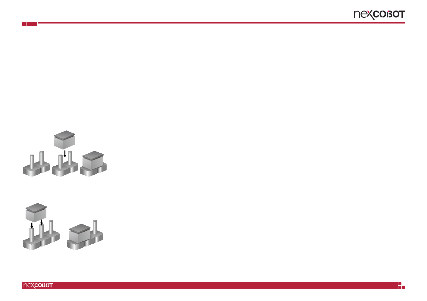
Jumper Settings
A jumper is the simplest kind of electric switch. It consists of two metal
pins and a cap. When setting the jumpers, ensure that the jumper caps are
placed on the correct pins. When the jumper cap is placed on both pins, the
jumper is short. If you remove the jumper cap, or place the jumper cap on
just one pin, the jumper is open.
Refer to the illustrations below for examples of what the 2-pin and 3-pin
jumpers look like when they are short (on) and open (off).
Two-Pin Jumpers: Open (Left) and Short (Right)
Three-Pin Jumpers: Pins 1 and 2 are Short
1
2
3
1
2
3
Table of contents
Other NEXCOBOT Motherboard manuals


