NEXENTRO Zigbee User manual

Zigbee Pushbutton Interface 2-gang 230 V
Zigbee Pushbutton Interface 2-gang 230 V
Art. no.: 57004000
Operating instructions
1 Safety instructions
To avoid possible damage, read and follow the following instructions:
Installation only by persons with appropriate knowledge and experience in the following
areas:
– 5 safety regulations and standards for the installation of electrical systems
– Selection of suitable tools, measuring devices, installation materials and, if necessary,
personal protective equipment
– Installation of the installation material
– Connection of devices to the building installation under consideration of local connection
conditions
Improper installation endangers your own life and the lives of users of the electrical system and
there is a risk of serious damage to property, e.g. through fire. You are at risk of personal liabil-
ity for personal injury and damage to property.
Contact an electrical contractor!
Even a lamp that is visibly switched off is permanently supplied with mains voltage. Therefore,
switch off the circuit breaker before replacing the lamp. Otherwise there is a risk of electric
shock when touching live parts.
The device must not be used in connection with consumers that could lead to danger to life or
limb or damage to property, e.g. heaters or electrical machines.
Read the instructions in full, observe them and keep them for future reference.
2 Device components
Figure1: Device components
(1) Push-button interface 2-gang 230 V
(2) Terminals
3 Intended use
– Zigbee transmitter for operating Zigbee-compliant devices, e.g. lamps, lights, plug ad-
aptors, dimmers, venetian blind actuators
– Operation with connected switches or push-buttons (normally open contact) and venetian
blind push-buttons
– Control via sensors with relay contact 230 V
– Integration into networks with Zigbee gateways from different manufacturers
– Mounting in appliance box according to DIN 49073 with a suitable cover
4 Product characteristics
– Zigbee Certified Product
– 2 inputs for switches, push-buttons or relay contacts 230 V from sensors
1 / 8
82403320 17.11.2021

Zigbee Pushbutton Interface 2-gang 230 V
– Switching, dimming, colour temperature control, venetian blind and shutter control, saving
and opening scenes
– Electronic short circuit protection
– Electronic over-temperature protection
– Operation without neutral conductor possible when supplied via a lamp wire
– Parameterising via app
– Updating via app
5 Operation
If the lamps in a group are in different switching states, they are synchronised when they are
first operated. Depending on the desired switching state, further operation is required.
For an unused input of the push-button interface the operating mode "off" should be set.
Switching or dimming the light using the push-button
Operating mode "Control" is set in the app.
■ Switching: Press the push-button briefly. The light switches on or off.
■ Dimming: Long press on the push-button. The dimming process ends when the push-but-
ton is released.
■ Colour temperature: Press the push-button twice briefly (double-click) in the switched-on
state to switch to the "Colour temperature" mode.
Long press on the push-button to change the colour temperature. With each new long
press, the direction of the color temperature change changes.
After a further double click, the device switches back to normal operation. After one
minute without operation, the device also returns to normal operation.
Switching the light using the switch
Operating mode "Switch" is set in the app.
■ Switching: Switch using the switch. Light switches off or on to the last brightness value.
■ Switching the light to 50% brightness: Switch twice using the switch.
■ Switching the light to 100% brightness: Switch three times using the switch.
Saving and opening scenes using the push-button
The Zigbee devices to be saved in a scene must first be assigned to the inputs of the push-but-
ton interface in the app.
Operating mode "Scene" is set in the app.
■ Saving the scene: Set the device to the required values. Long press on the push-button to
save the scene. For confirmation, the devices switch briefly off and on again.
■ Opening the scene: Press the push-button briefly.
To reset the scene, the "All Off" scene must be saved to an input.
Saving the scenes using the push-button can be deactivated via the app (default: activ-
ated).
Operating the curtain using the push-button
Operating mode "Blinds" is set in the app.
Push-button at input 1 raises the curtain, push-button at input 2 lowers the curtain. This
can be switched over in the app.
■ Moving the curtain: Press the push-button for longer than 1 second.
■ Stopping the curtain: Press the push-button briefly.
■ Adjusting the slats (venetian blind only): Press the push-button for less than 1 second.
2 / 8
82403320 17.11.2021

Zigbee Pushbutton Interface 2-gang 230 V
6 Fitting and electrical connection
To ensure good transmission quality, keep a sufficient distance from any possible sources of in-
terference, e.g. metallic surfaces, baby monitors, microwave ovens, WiFi routers and wireless
headphones.
DANGER!
Electrical shock when live parts are touched.
Electrical shocks can be fatal.
Before carrying out work on the device or load, disengage all the corresponding cir-
cuit breakers, secure against being switched on again and check that there is no
voltage!
Recommendation: Use an appliance box with an installation depth of 60 mm.
Operation of the push-button interface, in combination with a switch or push-button, is possible
with and without neutral conductor.
If there is a neutral conductor, the push-button interface should be connected to it in any case
(Figure 2).
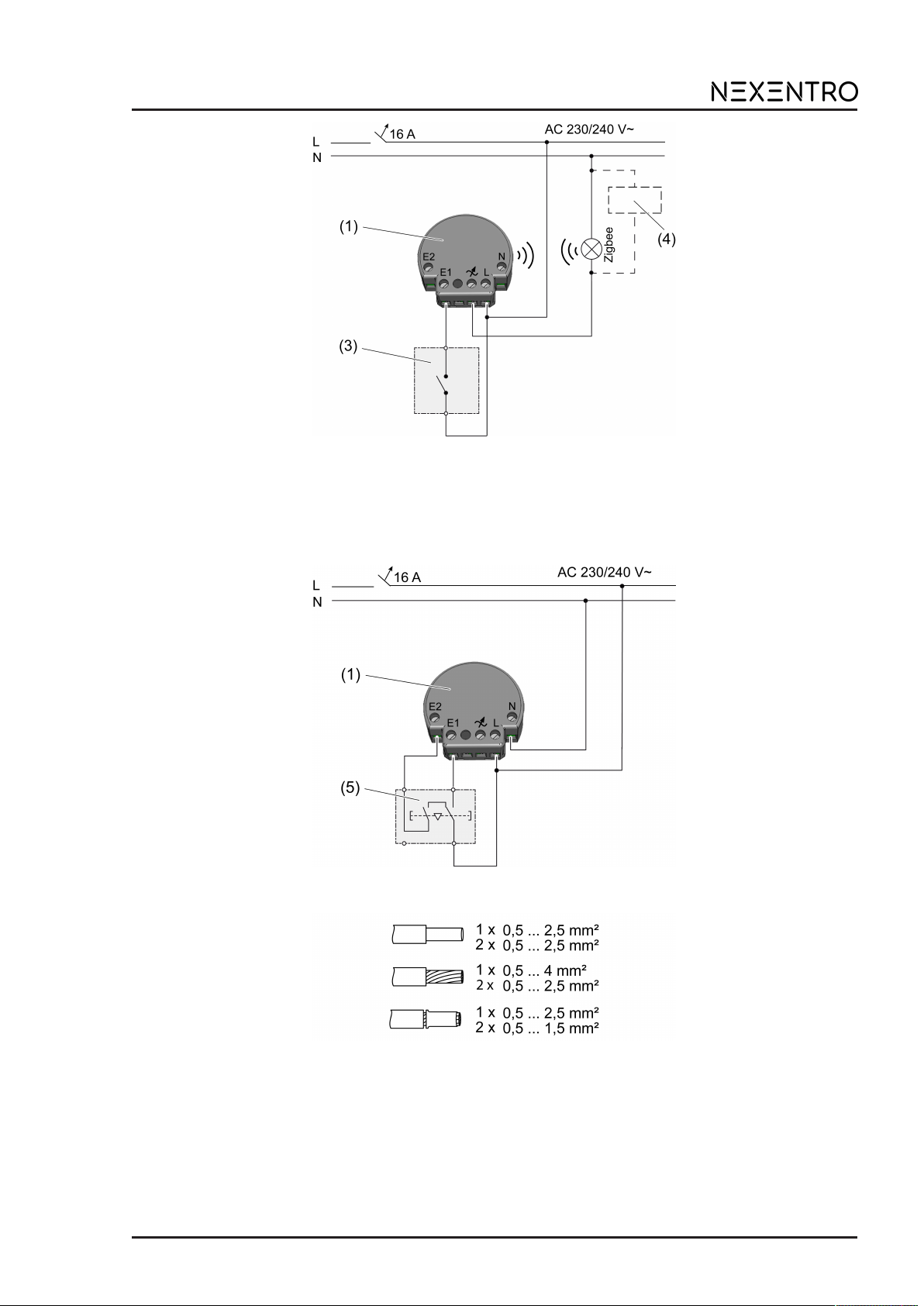
When operating without a neutral conductor, the lamp wire must be connected to the load ter-
minal 7. This is used for the power supply of the push-button interface, the load is not switched
over it. With some HV LED Zigbee lamps it may also be necessary to connect a compensation
module (4) to ensure the power supply of the push-button interface or a trouble-free operation of
the lamp (Figure 3).
To connect the push-button interface to a venetian blind push-button for operating curtains, the
connection to a neutral conductor is necessary (Figure 4).
Only HV LED Zigbee lamps may be connected to the load terminal 7.
■ Make the electrical connection according to the connection diagram (Figure 2), (Figure 3)
or (Figure 4). In doing so, note the clampable conductor cross-section (Figure 5).
■ When connecting without neutral conductor, connect a compensation module (4) if neces-
sary (Figure 3).
Figure2: Connection diagram switch or sensors (with neutral conductor)
(1) Push-button interface
(3) Switch, push-button or relay contact of a sensor
3 / 8
82403320 17.11.2021
Zigbee Pushbutton Interface 2-gang 230 V
Figure3: Switch connection diagram (without neutral conductor)
(1) Push-button interface
(3) Switch, push-button or relay contact of a sensor
(4) Compensation module (optional, see accessories)
Figure4: Venetian blind push-button connection diagram (5)
Figure5: Clampable conductor cross-section
Reset the overheating protection / short-circuit protection
If the electronic overheating or short-circuit protection has been triggered, disconnect the device
from the mains. After cooling the device is ready for use again.
4 / 8
82403320 17.11.2021

Zigbee Pushbutton Interface 2-gang 230 V
7 Commissioning
Commissioning is carried out via the NEXENTRO Config App, which step by step guides you
through the commissioning. This requires a mobile end device (smartphone or tablet) with a
Bluetooth interface and the Android or iOS operating systems.
The NEXENTRO Config App for the operating systems Android or iOS must be down-
loaded from the App Store (iOS) or Google Play Store (Android) and then installed.
App functions
– Joining an existing network
– Setting up your own network
– Assigning a device name
– Setting device parameters: Operating mode, venetian blind movement direction, scenes,
switch-on behaviour (dimming level, colour temperature)
– Connect the push-button interface to Zigbee actuators and Zigbee lamps
– Displaying the switching status of the connected switches or push-buttons
– Displaying device information: Device type, software version, hardware version
– Performing a software update
– Resetting to the default setting
The following operating modes can be set via the app:
–Control: For operation with one or two push-buttons for switching on and off and dimming
lights (default setting). When the push-button is operated, the load is switched over, e.g.
lights that are switched on are switched off and vice versa.
–Switch: For operation with one or two switches for switching loads on and off. When the
switch is operated, the load is switched over, e.g. lights that are switched on are switched
off and vice versa.
–Sensor: For operating sensors with relay contact 230 V, e.g. motion detectors. The load is
always switched on when the relay contact is closed and always switched off when it is
opened.
–Scene: For operation with two push-buttons for opening individual scenes.
–OFF: Input unused.
–Blinds: For operation with two push-buttons for operating a venetian blind or a shutter.
Registering new devices in the NEXENTRO Config app
NEXENTRO devices must be registered for commissioning in the NEXENTRO Config App. To
do this, the new unit must be put into pairing mode, which is active for approx. 1 minute after
mains voltage recovery.
■ Re-energise the NEXENTRO device and start the search in the NEXENTRO Config App.
■ Add the new device to the list of registered devices.
■ Assigning device names (optional).
With a registered device, connecting to a terminal is possible at any time.
Adding a push-button interface to a Zigbee network with gateway
To be able to control devices of a Zigbee network, the push-button interface must be added to
the network.
With certain gateways, adding to a network is done via the Touchlink function, see http://
www.nexentro.de/help.
■ Start the search mode for new devices in the app of the gateway to open the network for
further Zigbee devices. The function call depends on the gateway, e.g. "Search devices".
■ In the NEXENTRO Config App, set the operating mode for both inputs of the push-button
interface.
■ Select the Join Network function.
The push-button interface joins the Zigbee network.
5 / 8
82403320 17.11.2021

Zigbee Pushbutton Interface 2-gang 230 V
In the NEXENTRO Config App, all available Zigbee devices are displayed according to
the current operating mode of the push-button interface.
■ Select the devices to be controlled with the respective input of the push-button interface.
The push-button interface is not displayed in the app for some gateways, but can be con-
nected to available Zigbee devices from the network via the NEXENTRO Config App.
Creating a Zigbee network with the push-button interface (without gateway)
A Zigbee network can be created with the push-button interface and further NEXENTRO
devices can be added to the network. Adding additional Zigbee devices is always done via the
NEXENTRO device with which the Zigbee network was created.
■ In the NEXENTRO Config App, set the operating mode for both inputs of the push-button
interface.
■ Select the Create Network function.
The push-button interface has created a Zigbee network. The device search starts and
searches for devices to join the network.
■ Re-energise Zigbee lamps that are to join the network. For NEXENTRO devices, select
Join Network.
All available Zigbee devices are displayed according to the current operating mode of the
push-button interface.
■ Select the devices to be controlled with the respective input of the push-button interface.
Adding a push-button interface to a Zigbee network of NEXENTRO devices
The push-button interface can be added to a network created with another NEXENTRO device
via the function Create Network.
■ Carry out the device search in the NEXENTRO Config App for the NEXENTRO device
with which the Zigbee network was created.
■ Switch to the push-button interface to be added to the Zigbee network.
■ Set the operating mode for the two inputs of the push-button interface.
■ Select the Join Network function.
The push-button interface joins the Zigbee network.
All available Zigbee devices from the Zigbee network are displayed according to the cur-
rent operating mode of the push-button interface.
■ Select the devices to be controlled with the respective input of the push-button interface.
Joining a Zigbee network with a push-button interface via Touchlink
Requirement: The distance between the Zigbee transmitter and the push-button interface is 10
to 20 cm.
■ Select function Touchlink in the NEXENTRO Config App.
The push-button interface is ready to join the Zigbee network.
■ Trigger Touchlink on the Zigbee transmitter.
The push-button interface joins the Zigbee network.
In the NEXENTRO Config App, all available Zigbee devices are displayed according to
the current operating mode of the push-button interface.
■ Select the devices to be controlled with the respective input of the push-button interface.
Restoring the device to factory settings
Resetting the device to default settings is done via the app. The device deletes the assignments
to a network and all connections to Zigbee devices. The operating mode is set to "Control".
6 / 8
82403320 17.11.2021

Zigbee Pushbutton Interface 2-gang 230 V
After resetting the device to the default setting, it has to be removed from the
NEXENTRO Config App. On iOS equipment, the device also has to be removed from the
list of paired Bluetooth devices (Settings/Bluetooth). Otherwise, re-pairing will not be pos-
sible.
Deleting assignment to the Zigbee network and Bluetooth coupling
■ Switch off the supply voltage to the device four times in quick succession and switch it on
again. The pause between switching operations must be less than two seconds.
The network assignment and the Bluetooth coupling to mobile end devices are deleted.
8 Technical data
Rated voltage AC 230 / 240 V ~
Mains frequency 50 / 60 Hz
Connected load at 35°C
HV-LED lamps max. 100 W
When operating with a neutral conductor, the connection power at the load terminal in-
creases to a maximum of 150 W.
Power reduction
per 5°C in excess of 35°C -5%
when installed in wooden or dry construction walls -15%
when installed in multiple combinations -20%
Standby power max. 0.2 W
Power loss max. 1.2 W
Ambient temperature -5 ... +45 °C
Storage/transport temperature -25 ... +70 °C
Dimensions (LxWxH) approx. 48 x 45 x 20 mm
Total line length
pwr cable max. 100 m
Input cable max. 50 m
Zigbee
Communication protocol Zigbee 3.0 (router)
Radio frequency 2.400 ... 2,483 GHz
Transmission capacity 1 mW
Bluetooth
Radio frequency 2.402 ... 2.480 GHz
Transmission capacity max. 2.5 mW, Class 2
Transmitting range typ. 10 m
9 Accessories
Compensation module LED Order no. 51681000
7 / 8
82403320 17.11.2021

Zigbee Pushbutton Interface 2-gang 230 V
10 Declaration of conformity
Insta GmbH hereby declares that the radio system type art. no. 57004000 meets the directive
2014/53/EU. You can find the full article number on the device. The complete text of the EU De-
claration of Conformity is available under the Internet address: www.insta.de/instastorefront/ser-
vices/downloads
11 Warranty
We reserve the right to make technical and formal changes to the product in the interest of tech-
nical progress.
We provide a warranty as provided for by law.
Please send the unit postage-free with a description of the defect to our central customer ser-
vice office:
Insta GmbH
Service Center
Hohe Steinert 10
58509 Lüdenscheid
Germany
Insta GmbH
Postfach 1830
58468 Lüdenscheid
Germany
Telefon +49 (0) 2351 936-0
www.insta.de
8 / 8
82403320 17.11.2021
This manual suits for next models
1
Table of contents
Other NEXENTRO Media Converter manuals


