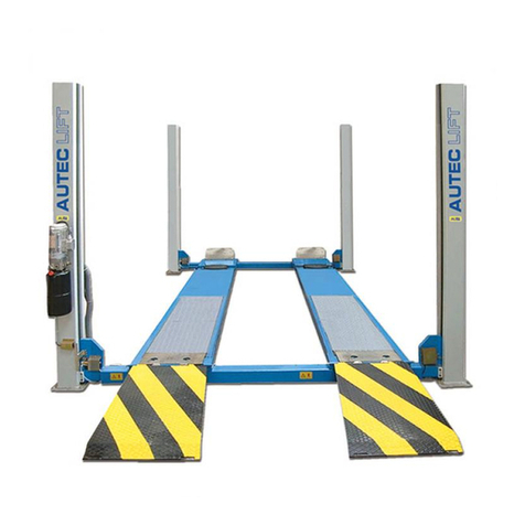
Nexion Molnar CM245-A User manual

Date: 09.10.2022
CM245-A
CM255-A
Installation Instructions
Read the operating
instructions before
working with the
unit
ALWAYS KEEP
operating instructions
ready to hand on the
unit

Before
taking into operation
check system compo-
nents, control, emer-
gency stop and safety
equipment for conditi-
on, damage and
correct function!
2 / 40
CM245/55-A
Please read this manual before you get started.
You must read and understand the precautions for safety purposes and any damages that may occur
to your property.
If these installation instructions are not followed strictly, the hoist is not covered by warranty.
Address: 3 Graham Street
Export Park
South Australia 5950
Ph:
Fax:
Email:
Web:
+61 (08) 8234 3611
+61 (08) 8234 4322
www.molnarhoists.com.au
Specifications/images subject to change without prior notice, Images and sketches are for illustration purposes only.

3 / 40
CM245/55-A
For further information - please see the foundation instructions:
Model Foundation instructions
CM245-A CM255-A T82346
These instructions indicate step by step how you ensure a trouble-free installation and a satisfactory operation. It
is therefore of vital importance that you take the necessary time and care in order to ensure that the installation
tolerances are not exceeded, otherwise the hoist will not function effectively and you will not benefit fully from
your purchase of the hoist.
NB: Note this arrow → .The hoist will throughout these instructions be shown from the drive-on direction.
NB: If these installation instructions are not followed strictly, the hoist is not covered by warranty.
Information for construction engineer or architect:
Model Quality of concrete according to EN206-1: Depth:
CM245-A
CM255-A
C25/30 (Fcyl = 25 N/mm² / Fcube = 30 N/mm²)
(B25 = 25 N/mm²)
160mm. (HILTI HST3)
Information for fitter:
The hoist has to be installed on an even floor and must not be installed in or close to construction joints
(min. distance = 200 mm). The thickness of the wearing surface on the raw concrete and clinkers, if any, must
be added to the length of the expansion bolts.
Expansion bolts used for the installation of the hoist in not-cracked concrete:
Model Expansion bolt
CM245-A CM255-A Hilti HST3 M16x145 45/25 *
*If alternative attachment is used the properties of this attachment must correspond to the Hilti bolt mentioned.
(The expansion bolts are not included in the delivery).
CM245-AS
Max. lifting capacity 4,500 kg
Lifting time 40 sec.
Lowering time 40 sec.
Lifting height 2013 mm
Stroke 1900 mm
Operation temperature ÷10°...60°
Noise level (measured at control unit at 1.6 m height) 85 dB (A)
Mains voltage Power
Revolutions/min
230-400/3/50+N +PE 3,0 kW
1400 rpm
400/3/60+N +PE 3,0 kW
1630 rpm
Pre-fuse 16A Class C (slow)
Max. operating pressure 210 bar
Setting of pressure control valve max. 230 bar
Output (at 50 Hz) 8.8 l/min
Output (at 60 Hz) 10.6 l/min
Oil contents approx. 8.4 L of 46
Oil displacement 4.8 L
3.4 Technical specifications

4 / 40
CM245/55-A
1. Tools requested.
2. Place all components as shown.
Remove transport plates from each column.

5 / 40
CM245/55-A
1
2

7 / 40
CM245/55-A
3
Max. portal height
M8x16
Min. portal height
M8x16
4
M6x25

8 / 40
CM245/55-A
5. Fit the prefitted safety ratchets on both posts.
6. Fit bracket with top limit switch in control post.
Re-tightening and adjustment of top limit switch is made at step 41.

9 / 40
CM245/55-A
5
6
M6x16
M12x25

10 / 40
CM245/55-A
7. Fill in oil on pump unit (see above specifications).
8. Fit bent bracket for pump unit on control post.
9. Fit pump unit on bracket.
10. The short hydraulic hose is fitted on pump and connected to the hydraulic hose on control post.

11 / 40
CM245/55-A
7
9
8
10
OIL
M6x25
M10x25

12 / 40
CM245/55-A
11. Fit plug for solenoid valve. (You will find the pre-wired plug tucked inside the post)
12. Fit motor cable on pump unit. For correct cable connection according to mains supply, see sketch.
13. Fit portal corners on posts as shown.
NOTE ! Pull the pre-fitted cables and hydraulic hoses out through the top of the extensions before raising
the posts.

13 / 40
CM245/55-A
11
13
12
Control post Opposite post
M8x20
( )
( )
3x230V
3x400V

14 / 40
CM245/55-A
14. Raise posts by means of straps.
Place posts as shown.
NOTE: The requirements of the local authorities concerning installation of hoists must always be
respected.
AS/NZS 1418.9 Section 3.4 Location of Vehicle Hoists
Vehicle hoists should be positioned so that any moving part of the hoist or the load is not less than
600mm away from the nearest fixed structure. Where a vehicle hoist is installed adjacent to any other
equipment which moves, the minimum clearance between any part of the hoist or the load and that
equipment shall be 600mm.
15. Drill holes for 2 expansion bolts in each post (to ensure that posts do not tilt during installation). Drill ho-
les through base plate. Fasten posts by means of expansion bolts - do not tighten bolts yet as definitive
adjustment of post position will take place later on (see step 20).

15 / 40
CM245/55-A
14
15
Min. 600 3250
Min. 2800
90°

16 / 40
CM245/55-A
16. Assemble portal.
Note ! Screws are not tightened before step 20.
17. Fit 4 pipe clamps loosely along the portal.

17 / 40
CM245/55-A
16
17
M8x20
1
4
2
3
M6x16

18 / 40
CM245/55-A
18. Fit bracket with height limit switch on left portal member.
19. Push rod for height limit switch into left portal member and fasten it on right portal member.

19 / 40
CM245/55-A
18
19
M8x20
M6x16

20 / 40
CM245/55-A
20. Raise portal and place on posts.
Adjust distance between posts if necessary.
Fasten portal - adjust distance between portal members if necessary - tighten bolts.
21. Check distance between posts and that posts are plumb - shim up if necessary.
22. Drill holes through base plate for remaining expansion bolts. Tighten all expansion bolts.
Torque for expansion bolts: 110 Nm.
NOTE!
Shim up base plates so that posts are vertical. As much base plate surface should be in
contact with the floor as possible. Molnar recommends at least 75% surface/shim to floor
contact, specifically in the middle of the base plate which must be in contact with the floor or
shimmed.

21 / 40
CM245/55-A
20
21
M8x20
22
Other manuals for Molnar CM245-A
1
This manual suits for next models
2
Table of contents
Other Nexion Lifting System manuals
Popular Lifting System manuals by other brands
ThyssenKrupp
ThyssenKrupp orion user manual

morse
morse 195AM-A Operator's manual
Custom Equipment
Custom Equipment Hy-Brid Lifts I Series MAINTENANCE & TROUBLESHOOTING MANUAL
BGS technic
BGS technic 9239 manual
Ranger Products
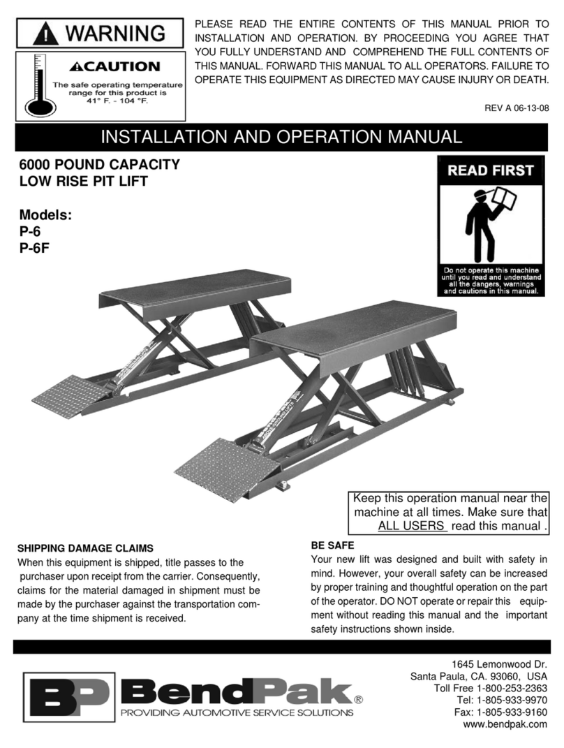
Ranger Products BendPak P-6 Installation and operation manual

stertil-KONI
stertil-KONI SKY-200 Installation, operation and maintenance instructions


