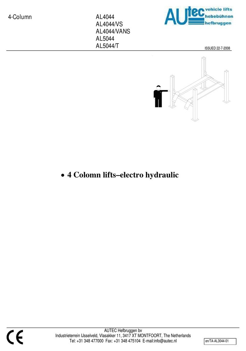
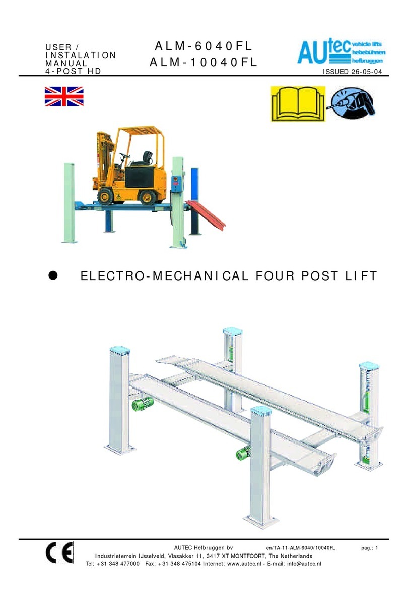
AUTEC AL4044 User manual

INSTALLATION-MANUAL
4-Colomn AL3044
AL4044
AL4044/VS
AL4044/VANS
AL5044
AL5044/T
ISSUED 22-7-2008
AUTEC Hefbruggen bv
•4-Colomn lifts – electro hydraulic
Industrieterrein IJsselveld, Vlasakker 11, 3417 XT MONTFOORT, The Netherlands
en/TD-AL4044-01

INSTALLATION-MANUAL
4-Colomn AL3044
AL4044
AL4044/VS
AL4044/VANS
AL5044
AL5044/T
ISSUED 22-7-2008
AUTEC Hefbruggen bv
INHOUDSOPGAVE PAG
1 Introduction 02
2 Packing, transport and storage 02
3 Safety specifications 02
4 Description of the lift 02
5 Installation 03
6 Connection to electrical mains 05
7 Safety checks 05
8 Goods received report 06
9 Electrical diagram 07
1. INTRODUCTION
CAUTION
This instruction manual is intended
for the assembly personnel who are
going to carry out the installation of
the lift.
2. PACKING, TRANSPORT
AND STORAGE
Every action involving the operation,
transportation or unpacking of the
equipment must only be done by
trained personnel who have a proper
knowledge of the lift, and who are
familiar with the contents of this
operating manual.
LIFTING AND MOVING THE
PACKING CRATES CONTAINING
THE EQUIPMENT
The wooden crates must be lifted and
moved with the help of a fork lift truck or
a lift crane. (Fig. 1)
Fig. 1
The equipment chosen must be
capable of lifting and moving the
equipment safely, keeping in mind
the dimensions of the vehicle, the
weight, the centre of gravity and
projecting and fragile parts.
STORAGE
The packed lift must always the placed
in a covered area at a temperature
between -10 oC and + 40 oC and must
not be exposed to direct sunlight.
OPENING THE CRATES
Check whether the machine have been
damaged during transportation, and
whether all the components as
mentioned in the Packing List are
physically present.
REMOVAL OF CRATES
The wood of the crates may be re-used.
It is strongly recommended
that you should first carefully read
the safety instructions.
3. SAFETY REGULATIONS
The manufacturer hereby refuses to
accept any responsibility for injury to
persons or damage to equipment or
property if it appears that incorrect
handling of the lift has taken place. This
instructions manual only describes the
operating- and safety aspects which
persons who are installing the machine
need to know. In order to understand
the terminology used in this manual, it is
necessary that the person performing
the installation work should have
specific experience in industrial work,
service, maintenance and repair
activities, and must also possess the
ability to explain the drawings and the
descriptions contained in this manual to
other people. At the same time he must
also be aware of the general and
specific safety regulations which apply
in the country where the lift is being
installed.
4. DESCRIPTION OF THE LIFT
(Fig.2)
The lift consists of the following :
Two platforms and four posts. The
columns are fixed to the floor with bolts.
The liftingsystem consists of a hydraulic
cilinder which converts the horizontal
movement by cabels and pulleys into a
vertical movement. The lift is controlled
by a controlbox mounted on the
controlpost.
Fig.2
CONTROL BOX (FIG.3)
The controlpanel of the controlbox
consists of the following:
11. Mainswitch
12. Lifting motion button
13. Descend button
14. Locking
Industrieterrein IJsselveld, Vlasakker 11, 3417 XT MONTFOORT, The Netherlands
en/TD-AL4044-02

INSTALLATION-MANUAL
4-Colomn AL3044
AL4044
AL4044/VS
AL4044/VANS
AL5044
AL5044/T
ISSUED 22-7-2008
AUTEC Hefbruggen bv
Fig.3
5. INSTALLATION
Installation may only be done
by persons authorised to do so.
BEFORE STARTING INSTALLATION,
PLEASE RECHECK ALL THE
CONTROL POINTS.
The lift must be installed in an enclosed
space where weather influences do not
have any effect. The place of installation
must be at a sufficient distance from the
storage locations of paint and wax, and
also rooms where there is a danger of
explosion.
ELECTRICAL POWER SUPPLY
POINT.
The client must ensure that there is a
power supply point near the installation
site, which satisfies all the applicable
legal requirements (see page 4). If such
power supply is not available, the
installation technician will arrange for
an emergency cable. The lift shall be
tested after the emergency power
supply has been dismantled. The client
must then arrange for a duly qualified
and recognised installation technician to
lay the final wiring.
IMPORTANT INSTALLATION
MEASURES
The lift must be installed taking into
account the dimensions of other objects
(Fig. 4), and the rules and regulations
applicable in the country where the lift is
installed.
In particular, attention should be paid to
the following :
The minimum height from the floor,
at the installation location, must be
5000 mm
The minimum distance from the
walls must be 1 m.
The minimum working area is 500
mm
Adequate room for working
Adequate room for maintenance,
access-/ and exit routes.
Position with respect to other
machines
In the neighbourhood of the power
supply point to ensure problem-free
connection.
Fig.4
During the installation no
unauthorized persons may be
present in the safety zone around the
lift.
•Remove the packaging from the
driving plates.
Place the driving tracks on dollies and
convey them to the general location of
installation. The driving track with the
cabling / hydraulics under the driving
plate must be installed on the same side
as the operating column (fig. 5)
Fig.5
Open the packaging of the columns and
place the columns on the installation
location. Fit the locking strips in the
columns. Take care: that this strip runs
behind the strip (1) in the centre of the
column (Fig.6).
Fig.6
Place the crossbeams on dollies. Take
care: that the crossbeam with the fuse
box is placed on the same side as the
operating column (Fig.7).
Fig.7
Remove the steel cable from under the
driving plate (Fig.8).
Fig.8
Lead the cables to the non-operating
side through the crossbeam. The cable
Industrieterrein IJsselveld, Vlasakker 11, 3417 XT MONTFOORT, The Netherlands
en/TD-AL4044-03

INSTALLATION-MANUAL
4-Colomn AL3044
AL4044
AL4044/VS
AL4044/VANS
AL5044
AL5044/T
ISSUED 22-7-2008
AUTEC Hefbruggen bv
in the 2nd duct should seen from below
pass through the short section of the
crossbeam. The cable in the 3rd duct
should seen from below pass through
the long section of the crossbeam
(Fig.9). Use for this purpose the string
supplied.
Through short part of the
crossbeam (2egroove)
Through long part of the
crossbeam (3egroove)
Fig.9
Short part
crossbeam
Long part
crossbeam
Fig.10
Lead 2 electricity cables from the rear
crossbeam to the front crossbeam. In
doing so lead the cable through the
same passage as the air hose (over the
I-profile).
Secure the crossbeam to the driving
plates with bolts and turn these hand-
tight (Fig.11).
Fig.11
Now lead the steel cables to the side of
the control unit in the same way through
the crossbeam as to the non-control
side.
Secure now the protective device on the
fixed driving plate.
Fig.12
Align the riding plates and secure the
bolts.
Connect the air hose that runs through
the driveway on both sides to the
locking cylinders.
Connect the air hose that emerges from
the crossbeam on the control side to the
compressed air supply.
Now fit the runners in the crossbeams.
Take care that the spring rings are fitted
to the bolts to secure the blocking plate
(Fig.13).
Fig.13
Fit the open guidance blocks to the
crossbeams. Take care that the
assembly bolt is in the centre to allow
for later adjustment. (Fig. 14).
Fig.14
Connect the electrical wiring to the
contact box on the crossbeam.
Place the columns by sliding them
against the crossbeams.
Fit the closed guidance blocks on the
exteriors of the crossbeams (Fig.15).
Fig.15
Now secure the lifting cables in the
column
Fig.16
FITTING THE CONTROL UNIT
Fit the control unit to the column.
Connect the cabling to the column as
detailed in diagram Fig.23
Industrieterrein IJsselveld, Vlasakker 11, 3417 XT MONTFOORT, The Netherlands
en/TD-AL4044-04

INSTALLATION-MANUAL
4-Colomn AL3044
AL4044
AL4044/VS
AL4044/VANS
AL5044
AL5044/T
ISSUED 22-7-2008
AUTEC Hefbruggen bv
Fit the safety switch at the bottom of the
column and connect it.
Remove the hydraulic hose from under
the platform and lead this together with
the pneumatic hose, the electrical cable
of the control unit, the return pipe and
any electrical cable for the lighting
through the flexible hose to the control
column (Fig.17).
Industrieterrein IJsselveld, Vlasakker 11, 3417 XT MONTFOORT, The Netherlands
Fig.17
Fill the oil reservoir.
Connect the electrical power to the
control unit
Align the columns, using if necessary
spacers secured with M12x100.
Suspend the safety bars in the column.
Fit the catch bars at the tops of the
columns with double nuts. 1 nut must be
located under the top plate. Caution:
the catch bar must be suspended loose
in the column (Fig. 18+19)
Fig.18
Fig.19
1. Adjust the column cables. Ensure
that the cables are taut when the
driving plates are on the floor.
2. Adjust the safety switches (cable
breach/weakness) to
approximately 1.5/ 2 mm (Fig.20)
Fig.20
Fit the pin that is to serve the switch at
the bottom of the column. Then adjust
the final switch at the bottom of the
column (Fig.21).
Fig.21
6. CONNECTING TO THE
MAINS
WARNING
The following actions must only be
carried out by duly authorised
personnel :
First check the following points before
connecting to the mains:
-
-
-
The electrical system at the
workplace must be protected
according to the applicable
standards.
The wires must be of the following
sizes : in the case of 400 V they
must be at least 2.5 mm2fuse max
16A. In the case of 230V 3-phase
supply, the wire size must be at
least 4 mm2.
-The supply cable must be provided
with an earthing wire, and must be
suitable for a firm and final
connection.
Connect the power supply cable to
the control cabinet according to
Fig. 23.
Put the main switch in the “1” position.
Check the direction of rotation of the
motor by pressing the lifting-motion
button.
7. SAFETY CHECKS
After the complete installation of the lift,
the responsible installation engineer
must check all the safety arrangements
on the lift to check whether they are
working properly.
CLEANING OF THE LIFT (Fig. 17)
The installation engineer responsible
must take care to see that the lift which
is installed is delivered to the client in a
'squeaky clean' condition.
en/TD-AL4044-05

INSTALLATION-MANUAL
4-Colomn AL3044
AL4044
AL4044/VS
AL4044/VANS
AL5044
AL5044/T
ISSUED 22-7-2008
AUTEC Hefbruggen bv
Industrieterrein IJsselveld, Vlasakker 11, 3417 XT MONTFOORT, The Netherlands
Fig.22
8. GOODS RECEIPT REPORT
The concerned installation engineer
must prepare a goods receipt report
after completion of the installation. The
goods receipt report must be prepared
as carefully as possible. Any complaints
and/or observations of the client will
also be noted in the report under the
heading ‘Remarks’. The report must be
signed by the responsible installation
engineer, and by the client. The
installation engineer will deliver the
report to the technical department. The
installation engineer must see to it that
the report are filled-in in time in the
service box.
en/TD-AL4044-06

INSTALLATION-MANUAL
4-Colomn AL3044
AL4044
AL4044/VS
AL4044/VANS
AL5044
AL5044/T
ISSUED 22-7-2008
AUTEC Hefbruggen bv
F1 = 2 Amp. Fuse
S1/S2 = Lift / descendlknop
Z1 = Buffe
r
S3 = Locking button
FC1-2-3-4 = Microswitch
FC5 = Microswitch
KM = Contact
Y1 = Hydr. solenoid valve
Y2 = Pneum. solenoid valve
Tem
p
= Time relais unlockin
g
Fig.23
Industrieterrein IJsselveld, Vlasakker 11, 3417 XT MONTFOORT, The Netherlands
en/TD-AL4044-07

INSTALLATION-MANUAL
4-Colomn AL3044
AL4044
AL4044/VS
AL4044/VANS
AL5044
AL5044/T
ISSUED 22-7-2008
AUTEC Hefbruggen bv
Fig.24
Industrieterrein IJsselveld, Vlasakker 11, 3417 XT MONTFOORT, The Netherlands
en/TD-AL4044-08
This manual suits for next models
5
Table of contents
Other AUTEC Lifting System manuals
Popular Lifting System manuals by other brands

Fleece
Fleece Duramax PowerFlo LB7 installation instructions
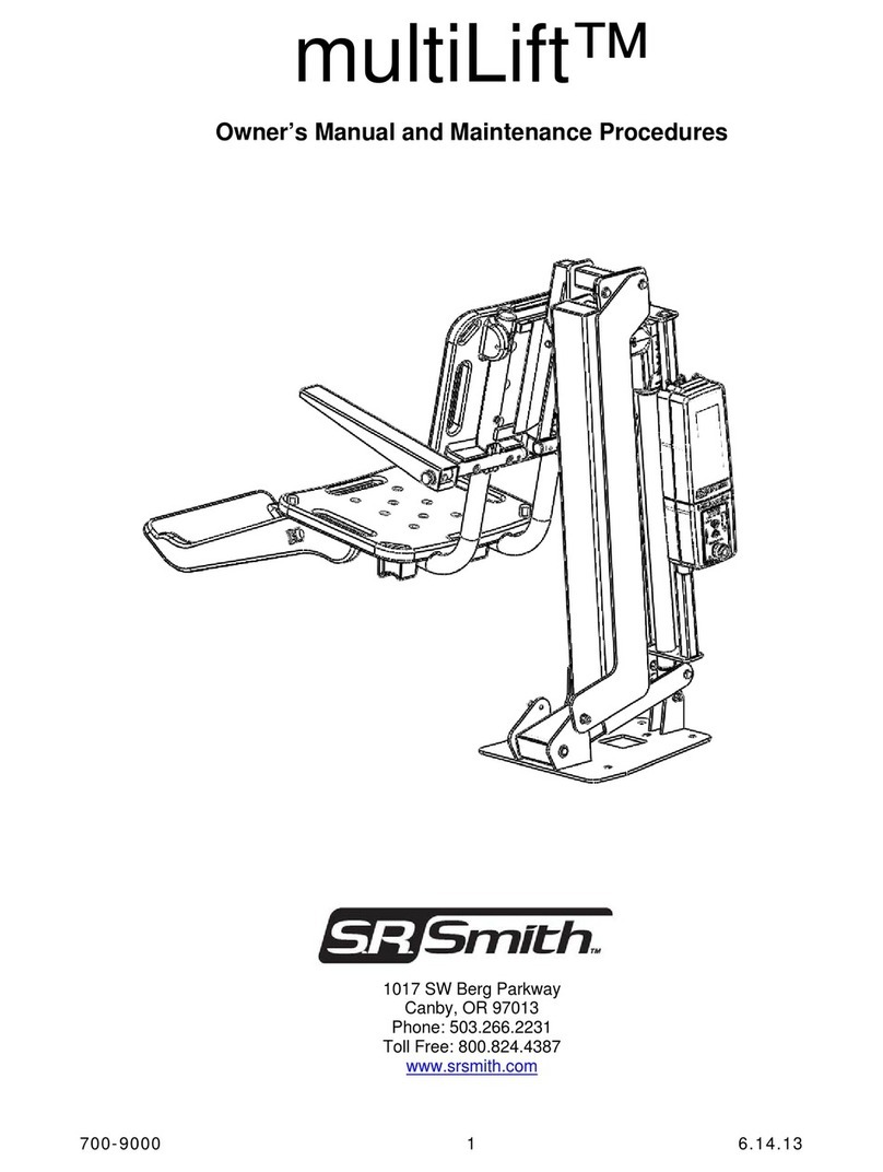
S.R.Smith
S.R.Smith MultiLift Owner's Manual and Maintenance Instructions
MINN KOTA
MINN KOTA 1854073 manual
Golden
Golden Tornado 4-CYLINDER installation manual
USM
USM QuickServe II installation manual
Ravaglioli
Ravaglioli G1000A99NP instruction manual

Haklift
Haklift MAGPML100 Original instructions
Columbus McKinnon
Columbus McKinnon Yale HTP Series operating instructions
DÖRR
DÖRR B-4WE 2.4G instruction manual

Atlas
Atlas BP10000X Installation & operation manual

Thiele
Thiele TWN 1884 operating instructions
Tuxedo
Tuxedo TP9KF ASSEMBLY & OPERATION INSTRUCTION MANUAL
