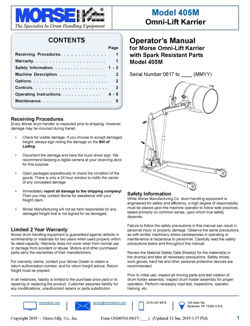
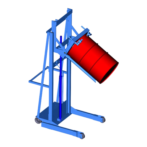
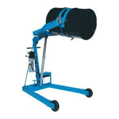
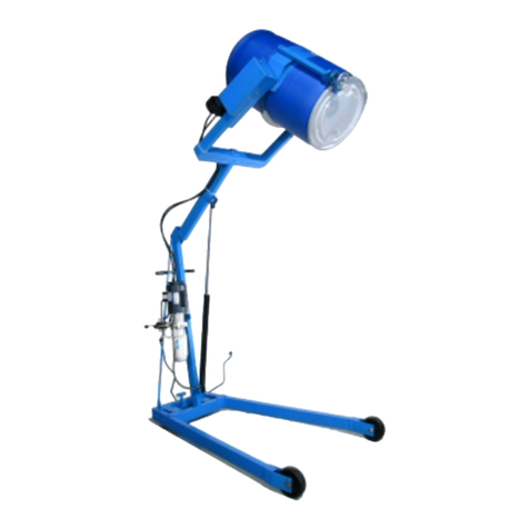
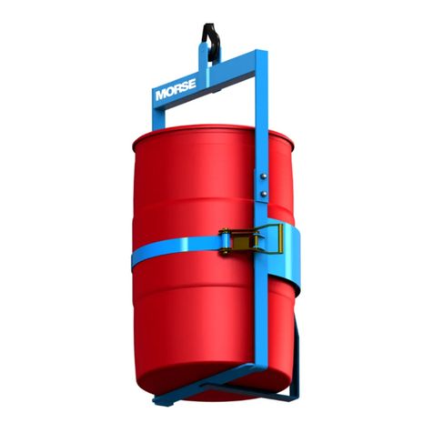
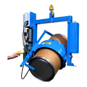
morse 195AM-A User manual

Contents
Page
Receiving Procedures. . . . . . . . . . . . . . . . . . . . 1
Warranty. . . . . . . . . . . . . . . . . . . . . . . . . . . . . 1
Safety Information. . . . . . . . . . . . . . . . . . . . . 1 - 2
Machine Description. . . . . . . . . . . . . . . . . . . 3
Operating Instructions. . . . . . . . . . . . . . .. . . . . 4
Maintenance. . . . . . . . . . . . . . . . . . . . . . . . . . 4
Parts Lists and Diagrams. . . . . . . . . . . . . . . . . . 5 - 6
Operator’s Manual
for Morse Kontrol-Karrier
with Spark Resistant Parts and
Air Power Tilt
Model 195AM-A
with Serial Number 240203 to 249030
Receiving Procedures
Every Morse drum handler is inspected prior to shipping. However,
damage may be incurred during transit.
Check for visible damage. If you choose to accept damaged•
freight, always sign noting the damage on the Bill of
Lading.
Document the damage and have the truck driver sign. We•
recommend keeping a digital camera at your receiving dock
for this purpose.
Open packages expeditiously to check the condition of the•
goods. There is only a 24 hour window to notify the carrier
of any concealed damage.
Immediately• report all damage to the shipping company!
Then you may contact Morse for assistance with your
freight claim.
Morse Manufacturing will not be held responsible for any•
damaged freight that is not signed for as damaged.
Limited 2 Year Warranty
Morse drum handling equipment is guaranteed against defects in
workmanship or materials for two years when used properly within
its rated capacity. Warranty does not cover wear from normal use or
damage from accident or abuse. Motors and other purchased parts
carry the warranties of their manufacturers.
For warranty claims, contact your Morse Dealer to obtain a
return authorization number, and for return freight advice. Return
freight must be prepaid.
In all instances, liability is limited to the purchase price paid or to
repairing or replacing the product. Customer assumes liability for
anymodications,unauthorizedrepairsorpartssubstitution.
Safety Information
While Morse Manufacturing Co. drum handling equipment is
engineeredforsafetyandefciency,ahighdegreeofresponsibility
must be placed upon the machine operator to follow safe practices,
based primarily on common sense, upon which true safety
depends.
Failure to follow the safety precautions in this manual can result in
personal injury or property damage. Observe the same precautions
as with similar machinery where carelessness in operating or
maintenance is hazardous to personnel. Carefully read the safety
precautions below and throughout this manual.
Review the Material Safety Data Sheet(s) for the material(s) in
the drum(s) and take all necessary precautions. Safety shoes,
work gloves, hard hat and other personal protective devices are
recommended.
Prior to initial use, inspect all moving parts and test rotation of chain
wheel and saddle assembly. Inspect saddle assembly for proper
operation. Perform necessary load test, inspections, operator
training, etc.
MORSE MFG. CO., INC. • 727 West Manlius Street • P.O. Box 518 • East Syracuse, NY 13057-0518
Phone: 315-437-8475 • Fax: 315-437-1029 • Email: service@MorseDrum.com • Webpage: MorseDrum.com
Copyright 2010 - Morse Mfg. Co., Inc. Form PL195AM-A (240203-249030) (Updated December 9, 2010 3:50 PM) 1
The Specialist In Drum Handling Equipment
Model 195AM-A
Kontrol-Karrier with Spark Resistant Parts
and Air Power Tilt

The Specialist In Drum Handling Equipment
Model 195AM-A
Kontrol-Karrier with Spark Resistant Parts
and Air Power Tilt
Operator’s Manual for Morse Model 195AM-A
Serial Number 240203 to 249030
MorseDrum.com
Copyright 2010 - Morse Mfg. Co., Inc. Form PL195AM-A (240203-249030) (Updated December 9, 2010 3:50 PM) 2
Safety Information (continued)
DANGER - Indicates a situation which, if not avoided, will result in
serious injury or death. This signal word is limited to the most extreme
situations.
WARNING - Indicates a situation which, if not avoided, could result in
serious injury or death.
CAUTION - Indicates a situation which, if not avoided, can result in
damage to the machine.
WARNING
The Kontrol-Karrier is designed to handle one drum of the types
listed under Machine Description. DO NOT attempt to handle
any other type of drum or object. DO NOT exceed the weight
capacity of 1,500 Lb. full drum and 800 Lb. half-full drum.
WARNING - Do Not Modify the Unit
Undernocircumstancesshouldanymodicationsbemadeto
theMorsemachinerywithoutfactoryauthorization.Anymodicationsmayvoidthewarranty.Thismachine
wasdesignedtoperformaspecicjobandalterationsmayresultininjurytooperatorormachine.
WARNING - No Loose Fitting Clothing
Wearclose-ttingclothingandsafetyequipmentappropriatetothejob.Loosettingclothingmaybecome
caught on the machinery and cause severe personal injury.
WARNING - Wear Safety Shoes
Wear safety shoes with non-slip soles and hard toe protection.
WARNING - Watch Out for Pinch Points
Stay clear of moving parts.
CAUTION - DO NOT allow drum to impact on oor, ground, or dumping station, etc.
Important
1. Review the Material Safety Data Sheet(s) for the material(s) in the drum(s) and take all necessary precautions. Safety shoes, work
gloves, hard hat and other personal protective devices are recommended.
2. Please read all instructions thoroughly before attempting to operate your new MORSE drum handler.
Machine Description
1. The model 195AM-A has a maximum capacity rating of 1,500 Lb. full drum and 800 Lb. half-full drum and is designed to lift, move
and pour 55-gallon steel drums. DO NOT exceed these ratings. Exceeding these ratings or handling drums other than those
mentioned above is unsafe and could result in equipment damage, excessive wear or awkward handling. Options and accessories
are available for model 195AM-A to enable handling different sizes and types of drums (see Options and Accessories).
2. The model 195AM-A is a “Group 1 - Structural and Mechanical” Below-the-Hook Lifting Device which is covered by the American
National Standard ANSI/ASME B30.20. The user should comply with all aspects of this standard.
3. When loading, unloading, operating, or maintaining your MORSE drum handler, always use care and good judgment. Maintain
securefootingandarmhold.Keephandsandlooseclothingawayfromallmovingparts.Neverallowanyonetobebelowany
part of a raised drum handler or drum. Read operating instructions and review the pictures in the sales brochure before operation.

The Specialist In Drum Handling Equipment
Model 195AM-A
Kontrol-Karrier with Spark Resistant Parts
and Air Power Tilt
Operator’s Manual for Morse Model 195AM-A
Serial Number 240203 to 249030
MorseDrum.com
Copyright 2010 - Morse Mfg. Co., Inc. Form PL195AM-A (240203-249030) (Updated December 9, 2010 3:50 PM) 3
Assembly Instructions
1. Install speed reducer oil vent plug and check oil level as shown in the speed reducer owners manual.
2. Air motor requires 20 PSI at 22 SCFM. Operating the air motor at higher pressures will reduce the life of the air motor and
power transmission components.
3. Prior to initial use, inspect all moving parts and test rotation of saddle assembly. Inspect cinch chain and cinch chain for
proper operation. Perform necessary load test, inspections, operator training, etc. as prescribed in the ANSI/ASME B30.20
standard.
Operating Instructions
1. WithKontrol-Karrierstandingontheoor,lowerhoistandengagehoisthookintotheliftingeye.
2. RaisehoisttoliftKontrol-Karrierclearofoorandmoveittothedrum.
3. Position Kontrol-Karrier at a height which aligns the saddle band with the
center of the drum.
4. With the cinch chain (item 25) hanging freely, push Kontrol-Karrier against
the drum to surround the drum with the saddle band.
5. Drape the cinch chain across the front of the drum and insert one chain link
into the slot on the ratchet (item 22). Turn the ratchet clockwise to tighten the
cinch chain around the drum.
6. Raise hoist and position the drum at the pouring station.
7. Pour the drum by pulling lever clockwise on the control valve (item 3).
8. After pouring is completed, rotate the drum back to vertical position and lower
hoisttoreturndrumtooor.
9. To remove drum: Pull ratchet clockwise to relieve pressure on ratchet teeth.
Lift pawl (item 18) to release teeth engagement and rotate ratchet counter-
clockwise to loosen chain and allow its removal from notch.
Maintenance
1. Inspect oil level in speed reducer.
2. Periodically inspect all moving parts, framework, cinch chain, and contact ar-
eas for signs of wear, fatigue, or loosening. Perform all inspections, load tests,
and maintenance according to the ANSI/ASME B30.20 standard.
3. Ensure all labels are in place. Product labels should be inspected periodically
and cleaned as necessary to maintain good legibility. Please contact Morse
Mfg. Co. for replacement labels.
Options and Accessories to enable handling different sizes and types of drums with model 195AM-A.
A smaller diam-
eter drum can be
handled if the cor-
rect size Diameter
Adaptor is installed.
Adaptors simply lift
in and out of the
drum holder. See
Diameter Adaptor
literature.
A 55-gallon plastic
drum can be han-
dled if the unit is
equipped with the
adjustable HDPS
Bracket (Part #
1465M-P). This
brackettsinto
socket tube on
the drum holder,
and prevents a
55-gallon plastic
drum from slipping
lengthways.
Model 55/30M-16
for 15.5” to 16” diameter drum.
Model 55/30M-19 for
18.5” to 19” diameter drum.

The Specialist In Drum Handling Equipment
Model 195AM-A
Kontrol-Karrier with Spark Resistant Parts
and Air Power Tilt
Operator’s Manual for Morse Model 195AM-A
Serial Number 240203 to 249030
MorseDrum.com
Copyright 2010 - Morse Mfg. Co., Inc. Form PL195AM-A (240203-249030) (Updated December 9, 2010 3:50 PM) 4
ITEM # QTY. PART # DESCRIPTION
1 2 1518-P NUT, 1/4-20 NYLON LOCK
2 1 2888-P MOUNT, CONTROL VALVE, 195A-A
3 1 2890-P CONTROL VALVE, 195A-A
4 2 1866-P WASHER, 1/4 USS 3/4 OD
5 2 1714-P HHCS, 1/4-20 X 3/4 GR2
6 1 4196M-P OVERHEAD WELD, 195AM-A
7 1 1473-P NUT, 5/8-11 REV HEX LOCK
8 1 565-P HHCS, 5/8-11 X 4-1/2 GR5
9 1 2854-P IDLER ARM W/ BEARINGS, 195A
10 1 570-P COLLAR, 1-1/2” ID
11* 2 560-P BEARING, 1-1/2” ID X 2”, GR
12 1 4201M-P SADDLE ASM, 195AM-A
13 2 540-P WASHER, 1-1/2 SAE FL 3” OD
14 1 726M-P HINGE PLATE CPT, 1/4” SR
15 1 4200M-P SADDLE WELD, 195AM-A
16 1 1296-P HHCS, 1/4-20 X 7-1/2 GR5
17 1 1297-P NUT, 1/4-20 REV HEX LOCK
18 1 168-P PAWL, WITH DRILLED HOLE
19 1 169-P SPRING, PAWL
20 1 170-P SCREW, 3/8 DIA X 5/8 SHOULDER
21 1 710-P RETAINER, RATCHET PUSH NUT 3/4
22 1 165SS-P RATCHET, STEEL-IT
23 1 4409-P GRIP, HANDLE 7/8” X 4-3/4” RED
24 1 165KIT-P KIT RATCHET CHAIN TIGHTENER
25 1 4408-P CHAIN, CINCH, 9/32 SS, 38 LINK
26 1 4081-P NUT, M8 ESNA, 8MM
27 1 525-P KEY, WOODRUFF, SIZE F, ASA1211
28 1 4079-P HHCS, M8 X 60 MM CL8.8, 8MM
29 2 1644-P WASHER, 1/2 SPLIT LOCK
30 2 1502-P HHCS, 7/16-14 X 1-1/4 GR5
31 1 4067-P SPEED REDUCER, 195, HELICAL
32 1 3652-P PLUG, SPEED REDUCER, GR SERIES
33 4 535-P HHCS, 3/8-16 X 1-1/4 GR5
34 4 1474-P WASHER, 3/8 SPLIT LOCK
35 1 290-A-2P MOTOR, 2HP, AIR, 56C
36 2 4676-P HYD FIT, PIPE ADAPTER 3/8-1/2
37 1 2891-P HOSE, 12’, SELF COILING 195A-A
38 1 AC980-P MUFFLER ASM, 290-A-2P, 195
39 1 4414-P COVER, CINCH CHAIN, FLEX PVC
40 1 4710-P PIN, BOW TIE COTTER, MOR
* Recommended spare parts

The Specialist In Drum Handling Equipment
Model 195AM-A
Kontrol-Karrier with Spark Resistant Parts
and Air Power Tilt
Operator’s Manual for Morse Model 195AM-A
Serial Number 240203 to 249030
MorseDrum.com
Copyright 2010 - Morse Mfg. Co., Inc. Form PL195AM-A (240203-249030) (Updated December 9, 2010 3:50 PM) 5
This manual suits for next models
2
Table of contents
Other morse Lifting System manuals

morse
morse 410-124 User manual

morse
morse 195A-A User manual

morse
morse 42 Series User manual

morse
morse 91 User manual

morse
morse 400A-72-120 User manual

morse
morse 520-114 User manual

morse
morse 525-N-115 User manual

morse
morse 185M-HD Series User manual

morse
morse 400A-60-120 User manual

morse
morse 81 User manual