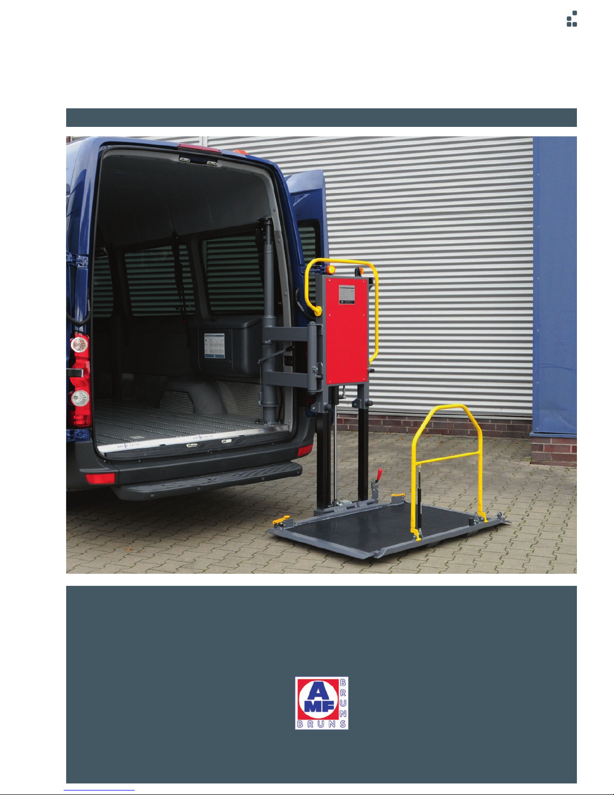
AMF-BRUNS BSL 350 User manual


Other manuals for BSL 350
2
Table of contents
Other AMF-BRUNS Lifting System manuals

AMF-BRUNS
AMF-BRUNS LINEARLIFT AL1 User manual

AMF-BRUNS
AMF-BRUNS BSL 350 User manual

AMF-BRUNS
AMF-BRUNS HUBMATIK K90 User manual

AMF-BRUNS
AMF-BRUNS LINEARLIFT AL1 User manual

AMF-BRUNS
AMF-BRUNS K70 User manual

AMF-BRUNS
AMF-BRUNS Linearlift Series User manual

AMF-BRUNS
AMF-BRUNS Easy-Flex-Ramp User manual

AMF-BRUNS
AMF-BRUNS K70 User manual

AMF-BRUNS
AMF-BRUNS BSL 350 User manual
Popular Lifting System manuals by other brands

Bend-Pak
Bend-Pak XPR-10 Series Installation and operation manual

Bend-Pak
Bend-Pak HD-9 Service manual

Bend-Pak
Bend-Pak LR-5T Service manual

ARJO HUNTLEIGH
ARJO HUNTLEIGH Maxi Twin Instructions for use

Bend-Pak
Bend-Pak HD-973P Installation and operation manual

FAL
FAL VL30F230B Installation and operating instructions


Sealey
Sealey ES502.V2 instructions

Custom Equipment
Custom Equipment HB-P830 Maintenance and troubleshooting manual

Nußbaum Hebetechnik
Nußbaum Hebetechnik 2.30 SL E Operating Instruction and Documentation

Caliber
Caliber V-Front Ramp Shield 13404 installation instructions

Grainger
Grainger 12R539 Operating instructions and parts manual

morse
morse Hydra-Lift Drum Karrier 400AM-60-124 Operator's manual