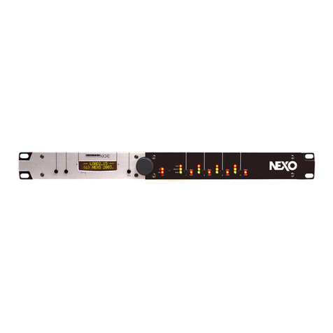
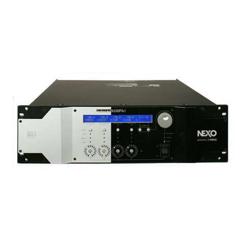
Nexo NX241 User manual

NX241 DIGITAL TDcontroller
User Manual

Norms
NormsNorms
Norms
This equipment has been tested and found to comply with the following European and
international Standards for electromagnetic Compatibility and electrical Safety:
• Electrical safety CEI65
• Radiated emission EN55022
• Conduction emissions EN55022
• ESD tests: EN61000-4-2.
• Immunity to fast electrical transients (sense input, RS232 link and AC inlet) EN61000-4-4
Safety Warning
Safety WarningSafety Warning
Safety Warning
This unit is fitted with 3-pin IEC standard power socket. For safety reasons the earth should not be
disconnected.
To prevent shock or fire hazard, do not expose the unit to rain or moisture.
To avoid electrical shock, do not remove covers. Dangerous voltages exist inside. Refer servicing
to qualified personnel only

PAGE 1/24 NEXO NX241 DIGITAL TDCONTROLLER
QUICK START
TABLE OF CONTENT
TABLE OF CONTENTTABLE OF CONTENT
TABLE OF CONTENT
QUICK START 2
LIST OF SUPPORTED SET-UPS 3
GENERAL DESCRIPTION 4
FRONT PANEL 4
REAR PANEL 5
CONFIGURATION 6
EQUALISATION & FILTERING 7
DELAY & POLARITY INVERSION 8
AUDIO INPUT/OUTPUT 8
GENERAL FUNCTIONS 9
MENU - USER UTILITIES 11
MAIN FAMILY SELECTION 11
USER SETTINGS 12
SYSTEM SETTINGS 14
CONFIGURATION SELECT. 15
VOLTAGE SELECTION AND FUSES 16
PRECAUTIONS 16
POWER CONNECTION 16
115/230 SWITCHING 16
DOWNLOAD 17
WARNING 17
INSTRUCTION 18
PROTECTION INFORMATION NOTES 20
PROTECTION 20
SOME WORDS ON AMPLIFIERS 22
POWER 22
CURRENT RATING 22
AMPLIFIER GAINS 22
GAIN VALUE 23
ADVANCED PROTECTIONS 23
TECHNICAL SPECIFICATIONS 24

PAGE 2/24
QUICK START
USER MANUAL LOAD1_80
DATE: 30/08/00 12:48
Quick Start
• This section contains a summary of most frequently asked questions by people who haven't
read the manual. You may be able to use the NX241 TDcontroller quite quickly as it has been
designed to be user friendly. However please devote some attention to reading this
manual. A better understanding of some specific features of the NX241 TDcontroller will
help you to operate your system to its full potential.
• Please ensure that the unit is set for the correct mains input voltage BEFORE use.
• WARNING: Information on the amplifiers used is MANDATORY. Before using your system
you MUST configure "MENU 2.6 AMP GAIN" and "MENU 2.7 AMP POWER". Failure to do so
or to properly connect the Sense Lines will invalidate the NEXO warranty on the attached
NEXO loudspeakers.
RESET
You can reset the unit without powering off by simultaneously depressing buttons A, B & SWAP
(!") at the same time.
Selecting cabinet family
Simultaneously depressing A & B buttons at A/C power up or during device RESET accesses the
system change menu. Keep the A & B Buttons until all LEDs light off. This will enable the
selection of any cabinet in any family. Using the rotary encoder, scroll through the configurations
and press ‘enter’ (!") to load the required settings.
Select your cabinet set-up
In MENU 3.0 you will be able to choose among the different set-ups within the same cabinet family.
(i.e. you don't have to modify the amplifier to cabinet wiring).
Navigating Menus
On the controller display screen, the number before the Function corresponds to the Menu
Number. To change the first number (this is the Main menu label) button A must be pressed. To
change the second number (this is the Submenu label) button B must be pressed. To select
options, turn the encoder wheel, or press the swap button (!"). Changes are immediate (no
validation is required unless clearly stated)
Back to default
In Menu 2.5 you have the possibility to put back all MENUS to the factory default (except the
amplifier information that you have entered (MENU 2.6 & 2.7)
Auto save
The current set-up is saved in case of power failure every two minutes after the last change. At
power up this set-up is restored

PAGE 3/24
LIST OF SUPPORTED PRESETS (LOAD1_80)
USER MANUAL LOAD1_80
DATE: 30/08/00 12:48
List of Supported presets (LOAD1_80)
At the time of printing, the following factory presets are supported by LOAD 1_80. Please refer to
the release notes if the software loaded in your NX241 is not LOAD 1_80.
Alpha Family
ALPHATD B1+M3 Configured: Input A to drive a 3-Way Alpha System
ALPHATD S2+B1+M3
SubTD S2-63Hz
Configured: Input A to drive a 4-Way Alpha System
ALPHATD S2+B1+M3
SubTD S2-80Hz
Configured: Input A to drive a 4-Way Alpha System
ALPHATD S2+B1+M3
S2-63Hz AUX inB
Configures Input B (right) to drive the SUB channel independently
ALPHATD S2+B1+M3
S2-80Hz AUX inB
Configures Input B (right) to drive the SUB channel independently
4 S2 cabinets
S2-63Hz
Configures all four channels to drive the S2 cabinet (crossover 63Hz)
4 S2 cabinets
S2-80Hz
Configures all four channels to drive the S2 cabinet (crossover 80Hz)
Alpha E Family
AlphaE STEREO Configures 2 passive Alpha EM + 2 B1-18 (or 2 Alpha EF) in stereo
ALPHAE Mono
AEM B1-18 S2-63
Configures one passive Alpha Em with one B1-18 bass and one S2 Sub
(crossover 63Hz)
ALPHAE Mono
AEM B1-18 S2-80
Configures one passive Alpha Em with one B1-18 bass and one S2 Sub
(crossover 80Hz)
PS Family
PS8TD Wideband
NO SUB
Configures PS8 cabinet in wideband position (without sub)
PS8TD Crossover
With LS400
Configures PS8 cabinet in crossover position with LS400 sub
PS10TD Wideband
NO SUB
Configures PS10 cabinet in wideband position (without sub)
PS10TD Crossover
With LS500
Configures PS10 cabinet in crossover position with LS500 sub
PS15TD Overlap
With LS1200
Configures PS15 passive cabinet in wideband position with LS1200 available.
PS15TD Crossover
With LS1200
Configures PS15 passive cabinet in crossover position with LS1200 available.

PAGE 4/24
GENERAL DESCRIPTION
USER MANUAL LOAD1_80
DATE: 30/08/00 12:48
GENERAL DESCRIPTION
Front Panel
Display & Indicators
(p.11)
Input Clipping (Red)
Menu - User Utilities (p.11)
Main Menu A selection
Mute/Solo buttons (p.11)
Menu - User Utilities (p.11)
Rotary encoder
Display & Indicators (p.11)
Peak limiting (Red)
Protection (Yellow)
Sense signal (Green)
Menu - User Utilities
(p.11)
SUB Menu B selection
Menu - User Utilities
(p.11)
Swap Channels (!")
A B !"
Display & Indicators
(p.11)
DSP Clipping

PAGE 5/24
GENERAL DESCRIPTION
USER MANUAL LOAD1_80
DATE: 30/08/00 12:48
Rear Panel
Expansion Board Blank Panel
Download (p.17)
RS232 Serial Port
BALANCED OUTPUTS
4 3 2 1
HIGH R
HF
HIGH L
MF
LOW R
LF
LOW L
SUB
R
S
2
3
2
SENSE INPUT
••••••••
+ 4 - + 3 - + 2 - + 1 -
FUSES
BALANCED INPUTS
RIGHT
A
UX.SUB
LEFT
FULL RANGE
Balanced Audio Input
(p.8)
Balanced Audio Output
(p.9)
Sense lines (p.9)
Voltage selection and fuses
(p.18)
1/ IEC Socket
2/ Power ON/OFF
3/ Fuse Holder
Voltage selection and fuses
(p.16)
Fuse Type & Rating
1 2 3

PAGE 6/24
GENERAL DESCRIPTION
USER MANUAL LOAD1_80
DATE: 30/08/00 12:48
Configuration
Global architecture is based upon a full 24 bit audio path with 48-bit core calculator running at 100
Million Instructions per Second. Featuring:
n 2 analogue inputs (balanced) 24 bit resolution ADC
n 4 analogue outputs (balanced) 24 bit resolution DAC
n 4 sense inputs (unbalanced) 18 bit resolution ADC
Set-up configurations possible:
n STEREO PASSIVE MODE WITH (or Without) MONO SUB (2 independent passive cabinets)
L R LSUB R
432121
L R L R
432121
n STEREO PASSIVE MODE WITH STEREO SUB & MONO PASSIVE WITH 2 SUBS
L R SUB L SUB R L R
432121
L R SUB 1 SUB 2 MAIN
4
3
2121
n ACTIVE 4 WAY & ACTIVE 3WAY (MONO)
L R
L
LF MF HFSUB
432121
L R
L
LF MF HFSUB
432121

PAGE 7/24
GENERAL DESCRIPTION
USER MANUAL LOAD1_80
DATE: 30/08/00 12:48
n ACTIVE 3 WAY plus AUX SUB on INPUT B
L R SUB LF MF HF
432121
n STEREO ACTIVE 2 WAY
L R LF L LF R HF L HF R
432121
Equalisation & Filtering
Subsonic and VHF filtering
Low and high-pass filters are used to filter out frequency components that could possibly
degrade the performance of the TDcontroller and amplifiers. The filters are optimised to work in
conjunction with overall system response.
The high pass filters are also extremely important as they optimise excursion at very low
frequency which is a very important safety factor. (So do not use set-ups which are not designed
for the cabinet you are using)
Equalising acoustical response
This equaliser section achieves the correction required to obtain a flat system response, as the
cabinets are acoustically designed for maximum efficiency on the whole frequency range. Active
rather than passive attenuation allows the lowering of amplifier voltages for a given output SPL and
therefore increases the maximum SPL achievable with the same amplifier.
Active equalisation also extends system bandpass especially at low frequencies where acoustical
performance is limited by cabinet size.
Crossover section
Crossover between different bands is tuned for every set-up of every cabinet. The crossover is
designed to ensure the best phase alignment possible over the crossover overlap.

PAGE 8/24
GENERAL DESCRIPTION
USER MANUAL LOAD1_80
DATE: 30/08/00 12:48
User set-up, Array EQ
A basic Array EQ is currently implanted in the NX241. The cut off frequency of a Low-shelving filter
is factory tuned for each cabinet setup. The user has access to the gain of this filter. Some more
sophisticated User EQ is currently under development. They will require the use of the upcoming
expansion board. Please read the readme.txt that comes along with every new software upgrade to
track eventual changes.
Delay & Polarity inversion
Input to output delay without filtering is 1.4ms (due to the digital processing). This delay will prevent
compatibility with analogue TDcontrollers. ANALOGUE AND DIGITAL TDCONTROLLER SHOULD NOT BE
MIXED IN THE SAME SYSTEM.
Factory set-up
Note that each output may contain a small phase adjustment delay at the crossover point. Also, a
polarity inversion may be performed. These adjustments are part of the factory set-ups and are
necessary to time-align the corresponding cabinet that is selected.
User set-up
Following user delay adjustment is possible:
GLOBAL: Affecting all channels at the same time (delaying all the system for application as delay
towers…)
MAIN: Affecting only CH3&4 for passive set-up and CH2, 3&4 for active channels (delaying the
main system if Sub basses are located behind it)
SUB: Affecting only CH1&2 for passive set-up and CH1 for active setup (delaying the Sub-bass
cabinet if main system are located behind it)
GLOBAL and MAIN/SUB delays are cumulative up to 150m per channel (about 450ms, 500 feet).
Audio Input/Output
Balanced Audio Input
The analogue inputs are on 3 pin female XLR connectors with positive and negative signal
polarities on pins 2 and 3 respectively. Pin 1 is coupled at high frequencies to the chassis using a
capacitor to limit screen currents, and to the analogue ground with a jumper link.
The input signal can be adjusted in MENU 1.1 HEADROOM in order to avoid clipping of the A/D
converter. See corresponding paragraph (MENU section)

PAGE 9/24
GENERAL DESCRIPTION
USER MANUAL LOAD1_80
DATE: 30/08/00 12:48
Balanced Audio Output
The analogue outputs are on 3-pin male XLR connectors with positive and negative signal
polarities on pins 2 and 3 respectively. Pin 1 is coupled at high frequencies to the chassis using a
capacitor to limit screen currents, and to the analogue ground with a jumper link. The output will
deliver a full-scale output of +28dBu(balanced 600Ω/ 1nF load.)
During A/C power up of the NX241, all outputs are muted by firmware-controlled relays (strapping
pin 2 and pin 3 of each output).
Connecting the audio outputs
Output stages are able to drive several amplifiers in parallel; however it is not advised to work with
loads of less than 600 Ohm. It is best to check with the impedance characteristics of the inputs -
supplied by the manufacturer - to check if the number of amplifier channels is acceptable. Where
precise information is not available (and taking 5 kΩas the minimum expected value) then seven
channels in parallel per output is a conservative maximum. In the case where input impedance is
20kΩit puts this value up to 30 amps channels
General Functions
System Protections
The following protection functions are performed. See "Protection Information Notes" page 20 for a
complete description. As the NX241 TDcontroller is common to all NEXO cabinets, see also the
release notes corresponding to each software revision for an update of the following list.
n Temperature Protection
n Displacement protection
n Peak limiting
n Interchannel regulation
n Physiologic Dynamic Control
Sense lines
Recommendations for sense line wiring
The Input impedance of the TDcontroller’s Sense inputs is very high, current is thus very low
although voltages are high. It is therefore not necessary to use a special type of cable. If the
processor is placed in the amp rack an unshielded cable can be used.

PAGE 10/24
GENERAL DESCRIPTION
USER MANUAL LOAD1_80
DATE: 30/08/00 12:48
Amplifier gain evaluation
This is used to determine the actual gain of the amp, and adjust for possible temperature drift,
amplifier input potentiometer adjustment or failure of this amp. This value is then compared to the
user-supplied nominal value and used for the displacement and temperature protection.
Remote sense
Line input (–18dB less than the amplifier gain) is possible and allows performing remote sense. At
this time these functions need additional accessories currently under development.
Reset
Holding down the three menu buttons (A, B, !") simultaneously will reset the unit. Reset has the
same effect as powering on and off the unit. The unit will mute (hardware) for 5 seconds with all
LED’s on. The unit will then return to the last set-up automatically saved (every 2 minutes).
Resetting the unit from the front panel is useful to change the cabinet family without powering off
and on (Press the three buttons to reset then let go of the swap button to enter into MENU 0). In
that case you will have to keep the A & B Buttons until all LEDs light off. Note that to execute a
download you will have to physically turn the unit off and then back on. (See "Download" page 17.)
Mute/Solo buttons
Front panel, direct access. The Mute (or Solo) mode is selected in the user menu. Please note that
these MUTEs are soft mute and are therefore not operating output relays.
Display & Indicators
User control of all settings is via two menu scroll pushbuttons, an additional assignable pushbutton,
an assignable rotary encoder and a backlit 16*2 character display.
Three LED’s per channel for sense (green), peak limit (red) protects (yellow). Four dedicated LED’s
are situated alongside the associated MUTE/SOLO button.
Two LED’s to indicate input overload and signal clipping into the DSP.
Default screen will pop up after 2 minutes and display the current set-up.
Serial link / Downloader
The unit can be RS232 linked to any PC in order to download new versions of software using a
DOS compatible Downloader program. (See "Download" page 17.)

PAGE 11/24
MENU - USER UTILITIES
USER MANUAL LOAD1_80
DATE: 30/08/00 12:48
Menu - User Utilities
On the controller display screen, the number before the Function corresponds to the Menu
Number. To change the first number (this is the Main menu label) button A must be pressed. To
change the second number (this is the Submenu label) button B must be pressed. To select
options, turn the encoder wheel, or press the swap button (!"). Changes are immediate (no
validation is required unless clearly stated).
Please refer to the release notes issued with each new download to track eventual menu changes.
Main Family Selection
Changing Cabinet Family
In order to prevent end-user changing between different
NEXO system set-ups during use, the following procedure
is obligatory. This procedure has been purposely designed
to avoid any mistake. It is nevertheless very easy to change
set-up among the same family (see menu 3)
Simultaneously depressing A & B buttons at A/C power up
or a device reset accesses the system change menu. You
can reset the unit without powering off by simultaneously
depressing buttons A, B & SWAP (!") at the same time.
Note: Selecting a new family will set all parameters to
factory default settings.

PAGE 12/24
MENU - USER UTILITIES
USER MANUAL LOAD1_80
DATE: 30/08/00 12:48
User settings
1.1 HEADROOM
Allows the user to adjust the headroom (4 steps -6, 0, +6,
+12) before the A/D converter without changing the overall
gain of the processor. Factory default is set to maximum
headroom (and so, maximum noise). This can be adjusted
if you feel the processor is too noisy for lower level
applications. Adjust the Headroom while the unit is
operating making sure that the red Input Clip and DSP Clip
LED's never flash. The operation is sonically transparent
and will not generate glitches while you are doing so.
1.2 DELAYS [Sub / Main / Global]
Each output channel can be delayed by up to a maximum
(global + individual delay) of 450ms (150m). See page 8
The unit can display in [FEET / METRES / SECONDS] as
required.
Delay is adjustable in 10cm (0.3ms) increments. The
control pot will accelerate through the adjustments faster
according to the speed of use.
1.3 OUT Levels
[global / HF /MF / LF / SUB]]
Adjust overall & separate TDcontroller gain with this menu.
These gain controls are provided to adjust the tonal balance
of the system by acting on separate channels. You can also
compensate for gain differences between different
amplifiers. (Although the use of differing gain structure
amplifiers in the same set-up is possible it is not
recommended).
Each of the individual or global gain is +/- 6dB. (Step 0.5dB)
1.4 Mute/Solo
Allows the user to switch the function of the front panel
channel buttons between Mute and solo mode

PAGE 13/24
MENU - USER UTILITIES
USER MANUAL LOAD1_80
DATE: 30/08/00 12:48
1.5 SAVE Set-up
It is possible to store and recall up to 10 user set-ups
(including EARTH LIFT) but excluding MUTE.
Additionally the current set-up is saved in case of power
failure every two minutes after the last change. At power up
this set-up is restored.
Set-ups are numbered from 1 to 10. When saving your set-
up you can choose a reference name up to 6 characters for
identification purposes.
NOTE: ALL SAVED SETUPS WILL BE ERASED WHEN
DOWNLOADING A NEW VERSION OF THE SOFTWARE.
1.6 RECALL Set-up
Recalling a user set-up is forbidden if the family of cabinet
is not the same.
When recalling a set-up, the unit will stay in the recall menu
allowing another selection for comparison. Switching from a
set-up to another is glitch-free and instantaneous (no
muting takes place).
1.7 Array EQ
One array EQ gain control of +/- 6dB (0.5dB step) is
included. This filter frequency is factory tuned.
20 100 1k 10k 20k
-10.00
-8.000
-6.000
-4.000
-2.000
0.0
2.0000
4.0000
6.0000
8.0000
10.000 AlphaTD Controller Array EQ / Frequency (Hz) / Gain (dB)

PAGE 14/24
MENU - USER UTILITIES
USER MANUAL LOAD1_80
DATE: 30/08/00 12:48
System settings
2.1 Revision [soft & hard rev]
Displays the revision number of the LOAD; DSP
SOFTWARE; FLASH BOOT; HARDWARE. Turn the
encoder to access to the different revision screens.
2.2 Security [password]
The user password facility allows switching between "free
access", "unit locked" and "Change password. The factory
default password is NEXO.
This allows you also to get into an INSTALLER menu.
Please contact your NEXO dealer if access required.
2.3 Earth Lift
[CHASSIS LINKED / CHASSIS LIFTED]
Earth Lift information is stored in the "user set-up" and
"automatic save set-up". It will keep the same state when
powering the unit on or off (also in the event of mains
failure)
2.4 SENSE GAIN
Allows switching between line level sense lines and
amplifier level sense lines. (0 or 18dB gain on the sense
line)
2.5 DEFAULT VALS
Restores the factory defaults. System related values like the
AMP GAIN and AMP Power will not change.

PAGE 15/24
MENU - USER UTILITIES
USER MANUAL LOAD1_80
DATE: 30/08/00 12:48
2.6 AMP GAIN
Adjustable from 20dB to 40dB nominal Amp Gain in 0.5dB
steps for each channel.
2.7 AMP POWER
Allows you to enter a Nominal Amp RMS power into 8ohms.
Adjustable from 200 Watts to 5000 Watts in 50W steps for
each channel. Warning: this power is specified into an 8-
Ohm load and does not represent the maximum power of
the Amp.
Configuration select.
3.1 System Config.
Changing a set of parameters within the same family is
made immediately and is barely audible.

PAGE 16/24
VOLTAGE SELECTION AND FUSES
USER MANUAL LOAD1_80
DATE: 30/08/00 14:38
Voltage selection and fuses
Precautions
Please ensure that the unit is set for the correct voltage for your local supply BEFORE use.
Operating voltage is indicated in the window of the main socket at the rear of the unit.
Power connection
Connection is made by means of an IEC standard power socket. The unit will operate with AC
main voltage between 90Vac and 125Vac 50-60Hz in 115v mode and 180Vac to 264Vac 50-60Hz
in 230v mode.
Please note that each mode requires a different fuse. Before
connecting to the main AC supply, ensure that the fuse fitted is the
correct type (time-lag T, slow blow) and rating (115V/T400mA or
230V/T200mA), as indicated on the rear panel, adjacent to the fuse
holder.
115/230 Switching
Voltage Selection Change requires no special tooling and can be performed in the field by
qualified service people.
DISCONNECT MAINS POWER TO THE UNIT, then follow these instructions:
• Open the fuse holder window in the power entry module located on the rear of the unit.
(External access)
• Remove the red fuse holder and insert the
corresponding fuse (115V/T400mA -
230V/T200mA) for the voltage required into the
opposite side of the holder.
• For safety reasons, when the fuse holder is
flipped around for voltage changing, the
conversion clip (small metal contact) should be
re-installed to the other side of the fuse holder.
Otherwise the fuse holder will not go back into the
housing completely and the power entry module
will not function.
The proper location of the conversion clip can be
checked in the following way. It should be located
to the left-hand side of the voltage number
selected, i.e., with the voltage label upright. See
diagrams opposite.
• Re-insert the red fuse holder, the required voltage
figure can now be seen in the fuseholder window.
• The unit is now ready for use.
APPLY FORCE ONLY TO THE SHOULDERS, NOT
TOTHE CONTACT FINGER INTHE MIDDLE.
CONVERSION CLIP
VOLTAGE SELECTION
PROPER CLIP LOCATION

PAGE 17/24
DOWNLOAD
USER MANUAL LOAD1_80
DATE: 30/08/00 12:48
Download
Information concerning downloading in this manual are general instructions. Please read
the specific instructions that come with each new LOAD (readme.txt) file.
Warning
The latest version of the downloader program (NXLoad.exe) provided with each upgrade set of
files must ALWAYS be used.
A "NULL MODEM" or "LAPLINK" cable is required to connect your PC RS232 serial port to the
NX241 RS232 serial port.
Connection from NX241 RS232 9-Pin Serial Port to PC’s COM port
NX241 RS232 serial port PC COM port
1 Don’t care 1
2 RXD ß---------Receive--------- 3
3 TXD -----------Transmit-------à2
4 Don’t care 6
5 SGND Signal ground 5
6 Don’t care 4
7 Don’t care 8
8 Don’t care 7
9 Don’t care 9
The NEXO download software is DOS compatible and has been tested on the following operating
systems:
n Microsoft MSDOS (V5.0 and above)
n DOS shell of Microsoft Windows 3.x
n DOS shell of Microsoft Windows 95
n DOS shell of Microsoft Windows 98
n Macintosh DOS compatible shell.
Note:
Due to the way Microsoft Windows NT addresses serial ports, the software does not currently run
on any version of Windows NT DOS shell. If you wish to use a machine that is running NT you will
have to make a bootable DOS disk, copy the downloader (NXLOAD.EXE) and the corresponding

PAGE 18/24
DOWNLOAD
USER MANUAL LOAD1_80
DATE: 30/08/00 12:48
LOAD (*.DLD) files to the disk and restart your machine in true DOS using this disk. [If you have
true DOS, to create a bootable disk under true DOS type the following "Format a: /s"]
Instruction
The files needed to execute your download will be provided as a *.ZIP file. You will have to extract
the content of this ZIP in a temporary directory using programs as Pkunzip or WINZIP (not provided
by NEXO). Once extracted you should have access to the following files:
• Two download (.DLD) files: the last official release version and the newly released version. If
you experience any problems with the new version, simply load back the old .DLD program to
return the unit to the previous version.
• A README.TXT that will contain download instruction
• WHATSNEW.TXT, which will inform you with all new features of the new LOAD.
• The downloader program NXLOAD.EXE
Execute the following procedure to load the new software into the NX241 Flash EPROM.
1) Connect the serial cable to both computer and NX241.
2) Execute your DOS shell (or start your machine from DOS).
3) At the DOS prompt, type the start command for the loader in the directory containing the files.
The correct syntax is as follows:
NXLOAD filename -COMport_number. <ENTER>
(e.g. NXLOAD LOAD1_80.DLD –1)
The downloader works with Com Ports 1 and 2 only. Com 3 and 4 cannot be used.
4) When you press <Enter> to invoke the command the following message appears on the
computer screen:
"Loading file...Waiting for NX241..."
Note: If the message is followed by a string of strange characters it is possible you have entered
the incorrect Com Port number. Hit ESCAPE to abort the procedure and start again. If nothing
happens, make sure that the cable is correctly wired and your computer COM port actually DOES
work before trying again. You can also try re-booting your machine.
5) Now to complete the procedure, you must set the NX241 to "Download" mode to make it ready
to accept the program.
Table of contents
Other Nexo Controllers manuals
