manuals.online logo
Brands
  1. Home
  2. •
  3. Brands
  4. •
  5. Smartgen
  6. •
  7. Controllers
  8. •
  9. Smartgen APC715N User manual

Smartgen APC715N User manual

Other Smartgen Controllers manuals

Smartgen HGM410E User manual

Smartgen

Smartgen HGM410E User manual

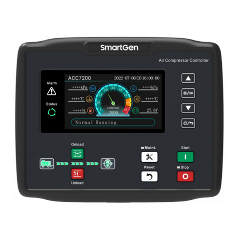
Smartgen ACC7200 User manual

Smartgen

Smartgen ACC7200 User manual

Smartgen HGM7100N Series User manual

Smartgen

Smartgen HGM7100N Series User manual

Smartgen HMAT880 User manual

Smartgen

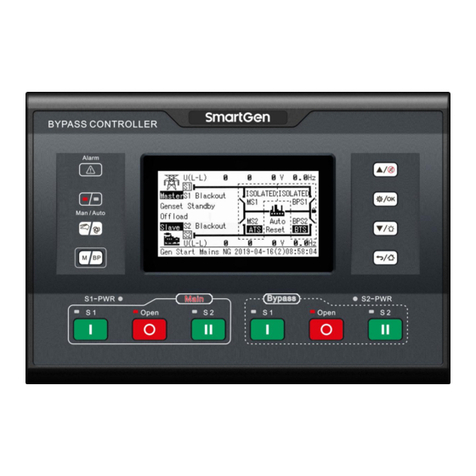
Smartgen HMAT880 User manual

Smartgen ALC700 SERIES User manual

Smartgen

Smartgen ALC700 SERIES User manual

Smartgen HGM9510 User manual

Smartgen

Smartgen HGM9510 User manual

Smartgen APC615 User manual

Smartgen

Smartgen APC615 User manual

Smartgen HGM1790N User manual

Smartgen

Smartgen HGM1790N User manual

Smartgen ALC700 SERIES User manual

Smartgen

Smartgen ALC700 SERIES User manual

Smartgen HGM400N Series User manual

Smartgen

Smartgen HGM400N Series User manual

Smartgen HGM8100A User manual

Smartgen

Smartgen HGM8100A User manual

Smartgen HAT530N User manual

Smartgen

Smartgen HAT530N User manual

Smartgen HGM9310MPU Series User manual

Smartgen

Smartgen HGM9310MPU Series User manual

Smartgen HAT530P Series User manual

Smartgen

Smartgen HAT530P Series User manual

Smartgen HSC960 User manual

Smartgen

Smartgen HSC960 User manual

Smartgen HGM6510 User manual

Smartgen

Smartgen HGM6510 User manual

Smartgen HGM7100N Series User manual

Smartgen

Smartgen HGM7100N Series User manual

Smartgen HGM6100N Series User manual

Smartgen

Smartgen HGM6100N Series User manual

Smartgen HAT530N User manual

Smartgen

Smartgen HAT530N User manual

Smartgen HEM4300 User manual

Smartgen

Smartgen HEM4300 User manual

Smartgen HAT160 User manual

Smartgen

Smartgen HAT160 User manual

Smartgen HAT160 User manual

Smartgen

Smartgen HAT160 User manual

Smartgen APC715 User manual

Smartgen

Smartgen APC715 User manual

Smartgen HGM6100N Series User manual

Smartgen

Smartgen HGM6100N Series User manual

Popular Controllers manuals by other brands

Sunricher SR-ZV9003T3-RGBW-US Installation

Sunricher

Sunricher SR-ZV9003T3-RGBW-US Installation

Ksenia intro Installation and configuration manual

Ksenia

Ksenia intro Installation and configuration manual

Inovance CAN200 Series manual

Inovance

Inovance CAN200 Series manual

Gauzy LC6 FLEX Controller Installation and operation guide

Gauzy

Gauzy LC6 FLEX Controller Installation and operation guide

Viking SLP-1 Technical practice

Viking

Viking SLP-1 Technical practice

CKD KBX-30E-U Series instruction manual

CKD

CKD KBX-30E-U Series instruction manual

Sharp Energy Sun Flux User manual & installation guide

Sharp Energy

Sharp Energy Sun Flux User manual & installation guide

Yamaha RCX40 user manual

Yamaha

Yamaha RCX40 user manual

AB Quality PowerFlex 400 Frames D-H Service bulletin

AB Quality

AB Quality PowerFlex 400 Frames D-H Service bulletin

Yamaha MJC8 owner's manual

Yamaha

Yamaha MJC8 owner's manual

AL-KO ATC operating instructions

AL-KO

AL-KO ATC operating instructions

Savant SmartControl 2 Deployment guide

Savant

Savant SmartControl 2 Deployment guide

GameSir T3S user manual

GameSir

GameSir T3S user manual

Kostal inveor operating manual

Kostal

Kostal inveor operating manual

Emerson Yarway 20-55 Operating and safety instructions

Emerson

Emerson Yarway 20-55 Operating and safety instructions

CoCo ACM-LV24 Quick installation guide

CoCo

CoCo ACM-LV24 Quick installation guide

Brooks SLA5810/20 Installation and operation manual

Brooks

Brooks SLA5810/20 Installation and operation manual

SIGMA TEK SR 011 Technical manual

SIGMA TEK

SIGMA TEK SR 011 Technical manual

manuals.online logo
manuals.online logoBrands
  • About & Mission
  • Contact us
  • Privacy Policy
  • Terms and Conditions

Copyright 2025 Manuals.Online. All Rights Reserved.

APC715N
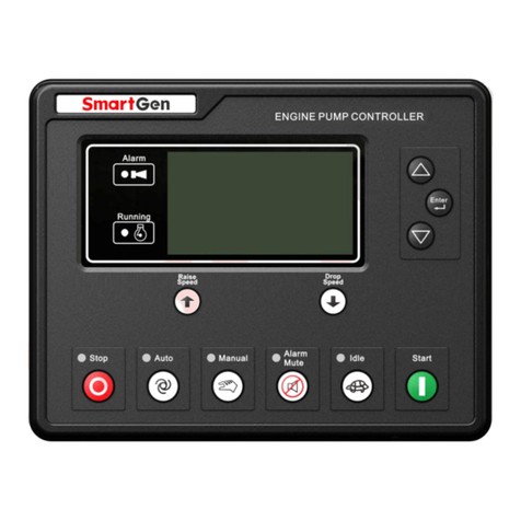
ENGINE PUMP CONTROLLER
USER MANUAL
APC715N Engine Pump Controller User Manual Page 2 of 72
CONTENTS
1 OVERVIEW .............................................................................................................................................. 6
2 PERFORMANCE AND CHARACTERISTICS ........................................................................................... 7
3 SPECIFICATION...................................................................................................................................... 9
4 OPERATION .......................................................................................................................................... 11
4.1 INDICATORS .................................................................................................................................. 11
4.2 KEY FUNCTIONS............................................................................................................................ 12
4.3 LCD DISPLAY................................................................................................................................. 14
4.3.1 MAIN DISPLAY........................................................................................................................ 14
4.3.2 USER MENU AND PARAMETER SETTING ............................................................................ 15
4.4 AUTO START/STOP OPERATION................................................................................................. 17
4.5 MANUAL START/STOP OPERATION ........................................................................................... 18
4.6 ON-LOAD CONTROL PROCEDURE................................................................................................ 18
4.7 ADJUST SPEED CONTROL PROCEDURE ..................................................................................... 19
5 MANUAL DPF REGENERATION........................................................................................................... 20
5.1 ILLUSTRATION .............................................................................................................................. 20
5.2 PANEL ICON DESCRIPTION OF POST-PROCESSING.................................................................. 20
5.3 DPF MANUAL REGENERATION OPERATION .............................................................................. 20
6 PROTECTION........................................................................................................................................ 22
6.1 WARNINGS .................................................................................................................................... 22
6.2 SHUTDOWN ALARM ..................................................................................................................... 25
6.3 COOLING SHUTDOWN ALARM .................................................................................................... 27
6.4 FAULT IDLE ALARM ...................................................................................................................... 27
6.5 INDICATION ALARM ..................................................................................................................... 28
7 WIRING CONNECTION ......................................................................................................................... 29
8 DEFINITION AND RANGE OF PARAMETERS ...................................................................................... 32
8.1 PARAMETER CONTENTS AND RANGES ..................................................................................... 32
8.2 DEFINED CONTENTS OF DIGITAL OUTPUT PORTS.................................................................... 47
8.2.1 DEFINED CONTENTS OF DIGITAL OUTPUT PORTS ................................................................ 48
8.2.2 CUSTOM PERIOD OUTPUT .................................................................................................... 53
8.2.3 CUSTOM COMBINED OUTPUT .............................................................................................. 54
8.3 DEFINED CONTENTS OF DIGITAL INPUT PORTS ....................................................................... 55
8.4 SENSOR SELECTION..................................................................................................................... 57
Table 16–Sensor Selection................................................................................................................ 57
8.5 CONDITIONS OF CRANK DISCONNECT SELECTION.................................................................. 58
Table 17–Crank Disconnect Conditions Selection........................................................................... 58
8.6 MAINTENANCE SETTING ............................................................................................................. 59
9 SENSOR SETTING ................................................................................................................................ 60
10 COMMUNICATION CONFIGURATION AND CONNECTION.............................................................. 61
APC715N Engine Pump Controller User Manual Page 3 of 72
10.1 ILLUSTRATION ............................................................................................................................ 61
10.2 RS485 COMMUNICATION DESCRIPTION.................................................................................. 61
10.3 TERMINAL RESISTANCE ............................................................................................................ 61
10.4 USB COMMUNICATION DESCRIPTION ..................................................................................... 62
11 TYPICAL APPLICATION..................................................................................................................... 62
12 INSTALLATION................................................................................................................................... 63
13 CONNECTION OF CONTROLLER WITH J1939 ENGINE................................................................... 65
13.1 CUMMINS QSL9 .......................................................................................................................... 65
13.2 CUMMINS QSM11(IMPORT) ...................................................................................................... 65
13.3 CUMMINS QSX15-CM570 .......................................................................................................... 66
13.4 CUMMINS QSZ13........................................................................................................................ 66
13.5 DETROIT DIESEL DDEC III/IV...................................................................................................... 67
13.6 MTU ADEC (SMART MODULE)................................................................................................... 67
13.7 MTU ADEC (SAM MODULE)........................................................................................................ 68
13.8 SCANIA ........................................................................................................................................ 68
13.9 VOLVO EDC3 ............................................................................................................................... 69
13.10 VOLVO EDC4 ............................................................................................................................. 69
13.11 VOLVO-EMS2............................................................................................................................. 70
13.12 YUCHAI ...................................................................................................................................... 70
13.13 WEICHAI .................................................................................................................................... 71
14 FAULT FINDING.................................................................................................................................. 72
APC715N Engine Pump Controller User Manual Page 4 of 72
Registered trademark
No.28 Xuemei Street, Zhengzhou, Henan, China
Tel: +86-371-67988888/67981888/67992951
+86-371-67981000(overseas)
Fax: +86-371-67992952
Email: sales@smartgen.cn
Web: www.smartgen.com.cn
www.smartgen.cn
All rights reserved. No part of this publication may be reproduced in any material form (including
photocopying or storing in any medium by electronic means or other) without the written permission of
the copyright holder.
SmartGen reserves the right to change the contents of this document without prior notice.
Table 1 –Software Version
Date
Version
Note
2022-12-06
1.0
Original release.
APC715N Engine Pump Controller User Manual Page 5 of 72
Table 2 –Symbol Instruction
Symbol
Instruction
NOTE
Highlights an essential element of a procedure to ensure correctness.
CAUTION
Indicates a procedure or practice, which, if not strictly observed, could result in
damage or destruction of equipment.
WARNING
Indicates a procedure or practice, which could result in injury to personnel or loss of
life if not followed correctly.
APC715N Engine Pump Controller User Manual Page 6 of 72
1OVERVIEW
APC715N Engine Pump Controller is used for diesel engine pump unit to realize the start/stop,
speed regulation, data measurement, alarm protection and “four remotes” function of engine pump. It
fits with LCD display, optional languages display (including Chinese, Englishes and other languages).
The exact parameters of engine and pump unit are indicated by the LCD display on the front panel and
the controller is reliable and easy to use.
Utilizing the GOV (Engine Speed Governor) control function, the controller is able to stabilize the
outlet/inlet pressure. Relay, GOV and CANBUS (SAE J1939) interfaces enable the controller to
communicate with various ECU or non-ECU engine pumps.
APC715N Engine Pump Controller adopts 32-bit ARM micro-processor technology with precision
parameters measuring, fixed value adjustment, time setting and threshold setting and etc. The majority
of parameters can be configured from front panel and all the parameters can be set using PC (via USB
port) and can be adjusted and monitored with the help of RS485 port. It can be widely used in a number
of pump control systems (land reclamation pump, fire pump, high-pressure pump, hydraulic pump, mud
pump, plunger pump, etc) with compact structure, simple connections and high reliability
APC715N Engine Pump Controller User Manual Page 7 of 72
2PERFORMANCE AND CHARACTERISTICS
——Adopts 32-bit ARM SCM, high hardware integration;
——240x128 pixel, 4.3-inch LCD display with backlight, multilingual interface (including Chinese,
English and other languages), which can be closen at the site, making commissioning
convenience for factory personel;
——Silicon front panel + hard screen acrylic;
——Dual RS485 communication port and can realize “four remotes” functions via MODBUS
protocol;
——Equipped with CANBUS port and can communicate with J1939 engine. Not only can monitor
frequently-used data (such as water temperature, oil pressure, engine speed, fuel consumption
and so on) of ECU, but also control start/stop, speed raising/droop via CANBUS port;
——GOV Function; outlet/ inlet pressure can be adjusted via GOV function. GOV port: Relay output;
Analog output (for speed control unit); CANBUS port (for engine control unit);
——With post-processing SCR inlet/outlet temperature, ureal level detection functions;
post-processing DPF regeneration state display and manual regeneration control function,
which are suitable for engines that meet the requirements of the fourth stage emission
standard of non-road mobile machinery;
——2 speed detection ports, the controller detects not only engine speed, but also gearbox speed;
——10 analog sensors; 3 fixed resistor types, 5 sensors can be flexibly configured as resistor type,
current type and voltage type, 2 fixed current type;
——More kinds of curves of temperature, oil pressure, fuel level can be used directly and users can
define the sensor curves by themselves;
——Precision measure and display parameters about engine and pump unit; e.g. engine high water
temperature, low oil pressure, over speed, high/low water pressure, over flow and other kinds
of fault indication and protection function;
——Two kinds of speed adjustment ways: manually and automatically; users can adjust the speed
on the panel;
——Idle control function;
——All output ports are relay-out;
——PLC programming function; can be applied to complex system;
——Self-defined main interface display function, the information is displayed by customized main
interface of PC;
——Multiple crank disconnect conditions (speed sensor, oil pressure) are optional;
——Wide power supply range DC(8~35)V, suitable for different starting battery voltage
environment;
——Event log function can record up to 200 items and the SPN of ECU alarm;
——Real-time clock, scheduled start & stop pump unit (can be set as start pump unit once a
day/week/month whether with load or not);
——Accumulative total run time A and B. Users can reset it as 0 and re-accumulate the value
which make convenience to users to count the total value as their wish;
——Can control engine heater, cooler and fuel pump;
——With maintenance function. Actions can be set when maintenance time out;
——All parameters used digital adjustment, instead of conventional analog modulation with
normal potentiometer, improving reliability and stability;
APC715N Engine Pump Controller User Manual Page 8 of 72
——IP65 due to rubber seal installed between the controller enclosure and panel fascia;
——Metal fixing clips enable perfect performance in high temperature environment;
——Modular design, anti-flaming ABS plastic enclosure, pluggable connection terminals and
embedded installation mode; compact structure with easy mounting.
APC715N Engine Pump Controller User Manual Page 9 of 72
3SPECIFICATION
Table 3 –Performance Parameter
Item
Contents
Operating Voltage Range
DC8V ~ DC35V, DC reverse protection
Battery Voltage
Resolution: 0.1V
Accuracy: 1%
Overall Consumption
<6W (Standby Mode:≤2W)
Speed Sensor
Voltage Range: 1.0V ~ 24V (RMS)
Frequency Range: 5Hz ~ 10000Hz
Charger (D+) Voltage
Range: DC0V~DC60V
Resolution: 0.1V
Accuracy: 1%
Analog Sensor
Resistor Input
Range: 0Ω ~ 6000Ω
Resolution: 0.1V
Accuracy: 1Ω (below 300Ω)
Voltage Input
Range: 0V ~ 5V
Resolution: 0.01V
Accuracy: 1%
Current Input
Range: 0mA ~ 20mA
Resolution: 0.01mA
Accuracy: 1%
Start Relay Output
16A DC24V DC supply output
Fuel Relay Output
16A DC24V DC supply output
Programmable Relay Output 1~ 6
7A DC24V DC supply output
Programmable Relay Output 7~10
7A DC24V volts free output
Digital Input Port 1~10
Low threshold voltage is 1.2V; high limit voltage is 60V
RS485 Interface
Isolation, half-duplex, 9600 baud rate,
maximum communication length 1000m
Ethernet Interface
Self-adaption 10/100Mbit
CAN Interface
Isolation, max communication length 250m, using Belden 9841
cable or equivalent
CE-EMC
EN 55032, EN55035
Vibration
5 Hz ~8 Hz: ±17mm
8 Hz ~ 100 Hz: 4 g
100Hz~500Hz: 2g
IEC 60068-2-6
Shock
50g, 11ms, half-sine, complete shock test from three directions,
and 18 times shock for each test
IEC 60068-2-27
Bump Test
25g, 16ms, half-sine
APC715N Engine Pump Controller User Manual Page 10 of 72
Item
Contents
IEC 60255-21-2
Production Compliance
According to EN 61010-1 installation category (over voltage
category) III, 300V, pollution class 2, altitude 3000m
Overall Dimensions
242mm x 186mm x 49mm
Panel Cutout
214mm x 160mm
Working Temperature
(-25~+70)°C
Working Humidity
(20~93)%RH
Storage Temperature
(-30~+80)°C
Protection Level
IP65, when water proof gasket ring inserted between panel and
housing.
Weight
1.0kg