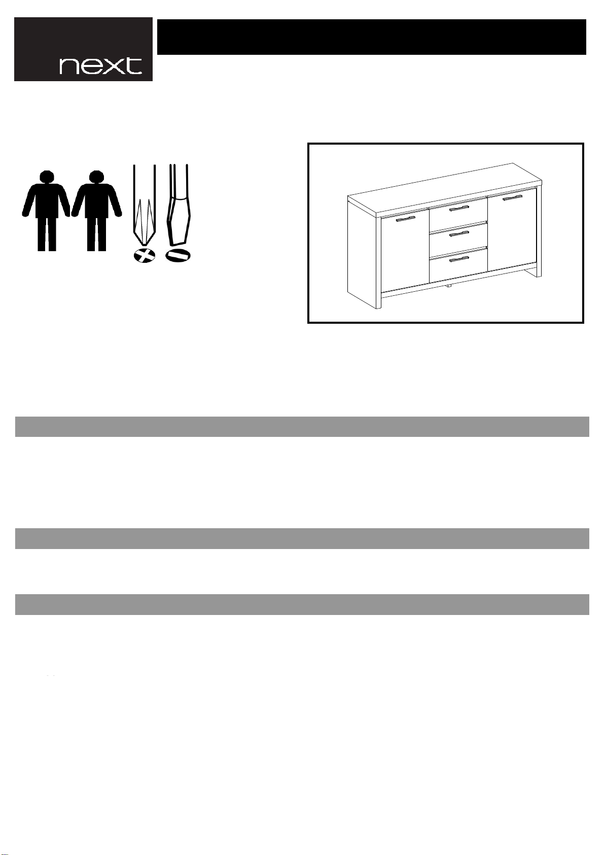
Next OPUS 782143 User manual
Other Next Indoor Furnishing manuals

Next
Next home FLORENCE 848694 User manual

Next
Next DECO WHITE CHEST 695745 User manual

Next
Next PORTIA 308301 User manual

Next
Next Claro 632491 User manual

Next
Next BRONX 685006 User manual

Next
Next CORSICA S User manual

Next
Next 243423 User manual

Next
Next LOGAN 118909 User manual

Next
Next 413470 User manual

Next
Next VALENCIA 898200 User manual

Next
Next HANLEY CORNER 320543 User manual

Next
Next 635770 User manual

Next
Next CORSICA 664566 User manual

Next
Next 878917 User manual

Next
Next BRONX NEST 168846 User manual

Next
Next HANLEY 638434 User manual

Next
Next ELKIN 123844 User manual

Next
Next 389846 User manual

Next
Next GROVE A37997 User manual

Next
Next 795914 User manual


Popular Indoor Furnishing manuals by other brands


Coaster
Coaster 4799N Assembly instructions

Stor-It-All
Stor-It-All WS39MP Assembly/installation instructions

Lexicon
Lexicon 194840161868 Assembly instruction

impekk
impekk Manual II Assembly And Instructions

Elements
Elements Ember Nightstand CEB700NSE Assembly instructions

JWA
JWA CARY 68429 Assembly instruction