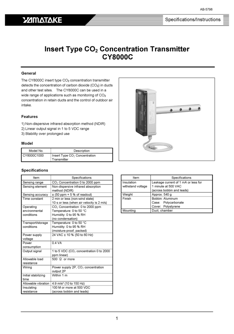
Yamatake 900 Series User manual

ST3000 Smart Transmitter Series 900
Electronic Differential Pressure/
Pressure Transmitter
Model : STD, STG, STA, STC,
STE, STR, STH and STU
User’s Manual
CM2-STJ100-2001
First issue: Apr. 1999 Rev.3: Oct. 2003

Copyright, Notices and Trademarks
While this information is presented in good faith and believed to
be accurate, Yamatake Corporation disclaims the implied war-
ranties of merchantability and fitness for a particular purpose and
makes no express warranties except as may be stated in its writ-
ten agreement with and for its customer.
In no event is Yamatake Corporation liable to anyone for any
indirect, special or consequential damages. This information and
specifications in this document are subject to change without
notice.
Copyright 1999 by Yamatake Corporation
All Rights Reserved

ST3000 Smart Transmitter Series 900 Electronic Differential Pressure/Pressure Transmitter 1
Safety
Instructions
Preface
Correct installation and periodic maintenance are essential to the safe use of your dif-
ferential pressure transmitters.
Read the safety instructions provided in this manual carefully and understand them
fully before starting installation, operation, and maintenance work.
Inspection
On delivery, make sure that the specifications are correct and check for any damage
that may have occurred during transportation. This equipment was tested under a strict
quality control program before shipment. If you find any problem in the quality speci-
fications, please contact your Yamatake Corporation representative immediately, pro-
viding the model name and serial number.
The name plate is mounted on the top of the enclosure.
Precautions
The following symbols are used in this manual to ensure user safety.
WARNING
This symbol is used to warn of hazards where failure to observe a safety instruction
may result in death or serious injury.
CAUTION
This symbol is used to warn of hazards where failure to observe a safety instruction
may result in injury or physical damage.
To ensure safe operation, be sure to observe the safety instructions provided on the
next page.
Yamatake Corporation will assume no responsibility, or offer any guarantee for any
failure resulting from violation of these safety instructions.

Safety Yamatake Corporation
2 ST3000 Smart Transmitter Series 900 Electronic Differential Pressure/Pressure Transmitter
Explosion protected Models
FM Explosionproof/Dust -ignitionproof Apparatus (in accordance
with NEC)
CAUTION
• Install the apparatus only in areas for which the apparatus has been approved.
• Seal each conduit entering the apparatus enclosure within 18 inches (457 mm)
from the enclosure.
• Do not open the apparatus enclosure when an explosive atmosphere is present.
1. Class I, Division 1 locations
1.1 Wiring methods
•Threaded rigid metal conduit, threaded steel intermediate metal conduit, or
Type MI cable with termination fittings approved for the location, can be
employed
•Threaded joints must be made up with at least five threads fully engaged.
1.2 Sealing
• Each conduit entering the apparatus enclosure is required to be sealed within 18
inches (457 mm) from the enclosure.
• The sealing of each conduit can be provided with a sealing fitting approved for
class I locations.
•Sealing compound must be approved and must not have a melting point of less
than 93 ° (200 °F).
• The minimum thickness of the sealing compound should not be less than the
trade size of the conduit and, in no case, less than 5/8 inch (16 mm).
• Splices and taps cannot be made in the fittings.
18 inches max.
Sealing Compound

Yamatake Corporation Safety
ST3000 Smart Transmitter Series 900 Electronic Differential Pressure/Pressure Transmitter 3
2. Class I, Division 2 locations
2.1 Wiring methods
•Threaded rigid metal conduit, threaded steel intermediate metal conduit,
enclosed gasketed busways, or Type PLTC cable in accordance with the pro-
visions of remote-control, signaling, and power-limited circuits (see NEC, Arti-
cle 725), or Type ITC cable in cable trays, in raceways, supported by messenger
wire, or directly buried where the cable is listed for this use; Type MI, MC, MV,
or TC cable with approved termination fittings can be employed.
2.2 Sealing
• Each conduit entering the apparatus enclosure is required to be sealed as shown
in 1.1.2.
3. Class II, Division 1 locations
3.1 Wiring methods
•Threaded rigid metal conduit, threaded steel intermediate metal conduit, or
Type MI cable with termination fittings approved for the location, can be
employed.
3.2 Sealing
• Where a raceway provides communication between the apparatus enclosure and
an enclosure that is not required to be dust-ignitionproof, suitable means must be
provided to prevent the entrance of dust into the former enclosure through this
raceway. One of the following means can be used: (1) a permanent and effective
seal; (2) a horizontal raceway not less than 10 ft (3.05 m) long; or (3) a vertical
raceway not less than 5 ft (1.52 m) long and extending downward from the dust-
ignitionproof enclosure.
• Seals are not required to be explosionproof.
4. Class II, Division 2 locations
4.1 Wiring methods
• Rigid metal conduit, intermediate metal conduit, electrical metallic tubing,
dust-tight wireways, or Type MC or MI cable with approved termination
fittings, or Type PLTC in cable trays, or Type ITC in cable trays, or Type
MC or TC cable installed in ladder, ventilated trough, or ventilated channel
cable trays in a single layer, with a space not less than the larger cable diam-
eter between the two adjacent cables, can be employed.
4.2 Sealing
• Sealing means must be provided as shown in 1.3.2.

Safety Yamatake Corporation
4 ST3000 Smart Transmitter Series 900 Electronic Differential Pressure/Pressure Transmitter
5. Class III, Division 1 locations
5.1 Wiring methods
•Rigid metal conduit, rigid non-metallic conduit, intermediate metal conduit,
electrical metallic tubing, dust-tight wireways, or Type MC or MI cable with
approved termination fittings, can be employed.
5.2 Sealing
• Sealing means are not required.
6. Class III, Division 2 locations
6.1 Wiring methods
• Wiring methods must comply with 5.1.
6.2 Sealing
• Sealing means are not required.

Yamatake Corporation Safety
ST3000 Smart Transmitter Series 900 Electronic Differential Pressure/Pressure Transmitter 5
CSA Explosionproof / Dust-ignitionproof Apparatus (in accordance
with CEC)
CAUTION
• Install the apparatus only in any hazardous (classified) locations for which the
apparatus has been approved.
• Seal each conduit entering the apparatus enclosure within 500 mm of the enclo-
sure according to the test report.
• Do not open the apparatus enclosure when an explosive atmosphere is present.
1. Class I, Division 1 locations
1.1 (a) Threaded rigid metal conduit or (b) cables approved for hazardous loca-
tions with associated cable glands approved for the particular hazardous
locations, can be used.
1.2 Threaded joints must have at least five full threads fully engaged.
1.3 Seals must be provided in conduit or cable systems to prevent passage of
gases, vapours or flames.
1.3.1 The seal is located in each run of conduit entering the apparatus enclosure
as close as practicable to and in no case more than 500 mm from the enclo-
sure.
1.3.2 The seal can be made in a sealing fitting approved for the location.
•Sealing compound must be approved for the purpose.
• The melting point of the sealing compound should not be less than 93°C (200°F).
• The minimum thickness of the sealing compound should not be less than the
trade size of the conduit and in no case, less than 5/8 inch (16 mm).
• Splices and taps are not made in the fittings.
0.5 m max.
Sealing Compound

Safety Yamatake Corporation
6 ST3000 Smart Transmitter Series 900 Electronic Differential Pressure/Pressure Transmitter
2. Class I, Division 2 locations
2.1 (a) Threaded metal conduit, or (b) cables approved for hazardous locations
with associated cable glands approved for the particular location, or (c)
Type TC cable installed in cable tray, or (d) Type ACWU cable with associ-
ated cable glands approved for the particular location, can be used.
2.2 Seals must be provided in conduit or cable systems to prevent passage of
gases, vapours or flames.
2.2.1 The seal is located in each run of conduit entering the apparatus enclosure as
close as practicable to and in no case more than 450 mm from the enclosure;
2.2.2 The sealing in Class I, Division 2 locations conforms to 1.3.2.
3. Class II, Division 1 locations
3.1 (a) Threaded rigid metal conduit, or (b) cables approved for hazardous loca-
tions with associated cable glands approved for the particular hazardous
location, can be used.
3.2 Where a raceway provides communication between the apparatus enclosure and
an enclosure that is not required to be dust-tight, the entrance of dust into the
former enclosure through this raceway must be prevented by (a) a permanent and
effective seal, or (b) a horizontal section not less than 3 m long in the raceway, or
(c) a vertical section of raceway not less than 1.5 m long and extending down-
ward from the dust-tight enclosure.
4. Class II, Division 2 locations
4.1 (a) Threaded metal conduit, or (b) cables approved for hazardous locations
with associated cable glands approved for the particular location, or (c)
Type TC cable installed in cable tray, or (d) Type ACWU cable with associ-
ated cable glands approved for the particular location, can be used.
4.2 Sealing of raceways conforms to 3.2.
5. Class III, Division 1 locations
5.1 Wiring methods
(a) Threaded rigid metal conduit or (b) cables approved for hazardous loca-
tions with associated cable glands approved for the particular hazardous
locations, can be used.
5.2 Sealing
Sealing means are not required.

Yamatake Corporation Safety
ST3000 Smart Transmitter Series 900 Electronic Differential Pressure/Pressure Transmitter 7
6. Class III, Division 2 locations
6.1 Wiring methods
The wiring methods in Class III, Division 2 locations conform to 5.1 except that
in sections, compartments, or areas used solely for storage and containing no
machinery. (In such sections, compartments, or areas, open wiring methods con-
forming to the rules for non-hazardous locations may be used.)
6.2 Sealing
Sealing means are not required.

Safety Yamatake Corporation
8 ST3000 Smart Transmitter Series 900 Electronic Differential Pressure/Pressure Transmitter
FM /CSA Nonincendive Apparatus
CAUTION
•The nonincendive apparatus can be installed only in Division 2 hazardous
(classified) locations for which the apparatus has been approved.
•Tampering and replacement of any components within the nonincendive
apparatus may impair safe use of the apparatus.
Installation requirements
1. Wiring of the nonincendive circuit is permitted using any of the methods suitable
for wiring in ordinary (unclassified) locations.
~Note Nonincendive apparatus is composed of all nonincendive circuits in
which any arc or thermal effect produced under normal operating condi-
tions of the apparatus is not capable of igniting the explosive atmo-
spheres. This protection technique is permitted for apparatus in those
Class I, Division 2, Class II, Division 2, and Class III locations. Nonin-
cendive apparatus looks like intrinsically safe apparatus but are not,
require associated apparatus (ex. shunt diode barriers).
2. In any raceway, junction box, or similar fitting, the conductors of the nonincen-
dive circuit cannot be placed with the conductors of any other system, unless (1)
the conductors of the two systems are separated by a suitable mechanical partition,
or (2) all of the conductors of either system are segregated by a grounded metal
shield.
3. It is recommended that separate nonincendive circuit conductors to be in sepa-
rate cables, unless (1) the conductors of each circuit are within a grounded metal
shield, or (2) the conductors of each circuit have insulation with a minimum thick-
ness of 0.01 inch (0.254 mm)
4. If a raceway (including conduit) and cable for a nonincendive circuit in Class
I, Division 2 or Class II, Division 2 locations is capable of transmitting flam-
mable atmosphere through the raceway and cable from the Division 2 location
to a non-hazardous location, it must be properly sealed at the boundary by using
of non-approved sealing fittings.

Yamatake Corporation Safety
ST3000 Smart Transmitter Series 900 Electronic Differential Pressure/Pressure Transmitter 9
ST3000 Smart Pressure Transmitters Series 900
Complying with ATEX Directive
1. Intrinsic Safety
1. Certification
~Note The apparatus is ensured to comply with the following European stan-
dards.
EN 50014 (Electrical apparatus for explosive gas atmospheres)
EN 50020 (Intrinsic safety “i”)
EN 50284 (Electrical apparatus for equipment group II, Category 1 G)
Certificate No.: KEMA 03ATEX1225 X
Specific type of protection: II 1 G EEx ia IIC T4
where each letter or symbol represents the meaning as follows.
II: Equipment group II (Equipment for use in places other than mines).
1: Category 1 (Highest category equipment allowed to be installed in Zone
0).
G: Gas ignition protection.
EEx: Apparatus being applied by one of the types of protection specified by
EN standards.
Ia: Intrinsically safe apparatus with a level of protection “ia”.
IIC: Group IIC (The apparatus of IIC can be used in air-gas mixture of hydro-
gen or acetylene).
T4: Temperature class T4 (Surfaces of the apparatus of T4 do not exceed
135? at the maximum ambient temperature of 60°C).

Safety Yamatake Corporation
10 ST3000 Smart Transmitter Series 900 Electronic Differential Pressure/Pressure Transmitter
2. Caution
a) Special condition for safe use (X of Certificate No.)- Because the enclosure of the
apparatus is made of aluminum alloy, if it is mounted in an area where the use of
category 1 G apparatus is required, it must be installed such, that, even in the event
of rare incidents, ignition sources due to impact or friction sparks are excluded.
b) Any modification within the apparatus may impair the intrinsic safety. Unautho-
rized modifications including replacement with non-factory components are not
permitted.
c) Never operate the apparatus at such a process temperature and/or an ambient tem-
perature that exceed the maximum specified value.
~Note The maximum surface temperature of the electrical components is
ensured not to cause temperature ignition of the flammable mixture pro-
vided that both the maximum process temperature specified for each
model and the maximum ambient temperature of 60°C are not exceeded.
d) The circuit of the apparatus must be considered to be connected to earth.
~Note If the insulation test is required, the test voltage of 50V r.m.s. a.c. should
be applied between the circuit and the frame of the apparatus because the
surge protection devices will conduct at more than 50V r.m.s. a.c. (The
frame is connected directly with the earth terminal inside the terminal
compartment).
3. For Safe Use
~Note Further information for safe use is given by the following documents.
EN 60079-14 (Electrical installations in hazardous areas)
EN 60079-17 (Inspection and maintenance)
EN 60079-19 (Repair and overhaul)
a) Associated apparatus or safety barriers to be connected with the intrinsically safe
apparatus must be selected from those that have been certified as EEx ia IIC in
accordance with ATEX Directive.
b) The permitted output parameters of the associated apparatus, Uo, Io, Po, Co and Lo
must be specified as follows.
Uo < Ui = 30V
Io < Ii = 100 mA
Po < Pi = 1W
Co > Ci = 3 nF
Lo > Li = 0.5 mH
where the values of Ui, Ii, Pi, Ci and Li have been established for the intrinsically
safe apparatus.

Yamatake Corporation Safety
ST3000 Smart Transmitter Series 900 Electronic Differential Pressure/Pressure Transmitter 11
c) The maximum capacitance and inductance of a cable which makes interconnection
between the apparatus and the associated apparatus must satisfy the following rela-
tionships.
Cc < Co - Ci
Lc < Lo - Li
where Cc and Lc are allowable total values of the cable parameters. If those values
are not determined by the specification of the cable manufacturer, the values can be
measured or estimated based on the applicable values of 200 pF/m and 1 µH/m
(refer to EN 60079-14).
d) When the associated apparatus is not galvanically isolated (for example a diode
safety barrier), the earthing terminal of the associated apparatus should be connected
to a high integrity earth in such a way as specified by the manufacturer of the associ-
ated apparatus.
e) The intrinsically safe circuit cable interconnecting the apparatus and the associated
apparatus must be separated from any non-intrinsically safe circuit cable unless
either of the cables is armoured, metal sheathed or screened.
The metal sheath or screen of either circuit cable must be earthed at one point only;
normally at the non-hazardous area.
~Note Multi-core cables may contain more than one intrinsically safe circuit but
intrinsically safe and non-intrinsically safe circuits should not be carried
in the same multi-core.
f The external earthing terminal of the apparatus must be connected to the equipo-
tential bonding system which includes protective conductors, metal conduits,
metal cable sheath, steel wire armouring and metallic parts of structures (but does
not include the neutral conductors of the power systems) unless the metallic enclo-
sure is secured to the metallic structure.
g) If necessary, the dedicated hand-held communicator, Smart Field Communicator
Model SFC160 (Certificate No.: KEMA 00ATEX1074 X) can be connected across
the terminals of the apparatus by removing the cover of the terminal compartment.
h) Because the communicator is housed with plastic material, care should be taken
for handling of the communicator against electrostatic charging. For example,
cleaning of the housing should be done only with a damp cloth.
II. Flameproof Enclosure
1. Certification
~Note The apparatus is ensured to comply with the following European stan-
dards.
EN 1127-1 (Explosive atmospheres - Explosion prevention and protection.
Basic concept and methodology)

Safety Yamatake Corporation
12 ST3000 Smart Transmitter Series 900 Electronic Differential Pressure/Pressure Transmitter
EN 50014 (Electrical apparatus for explosive gas atmospheres)
EN 50018 (Flameproof enclosure “d”)
EN 50281-1-1 (Electrical apparatus for use in the presence of combustible
dust)
Certificate No.: INERIS 99ATEX0010 X
Specific type of protection: II 2 G D EEx d IIC T6
where each letter or symbol represents the meaning as follows.
II Equipment group II (Equipment for use in places other than mines).
2 Category 2 (Equipment allowed to be used in Zone 1 for gases or Zone
21 for dusts).
G Gas ignition protection.
D Dust ignition protection.
EEx Apparatus being applied by one of the types of protection specified by
EN standards.
d Flameproof enclosure in accordance with EN 50018.
IIC Group IIC (The apparatus of IIC can be used in air-gas mixture of
hydrogen or acetylene).
T6 Temperature class T6 (Surfaces of the apparatus of T6 do not exceed
85°C at the maximum ambient temperature of 60°C).
2. Caution
a) The apparatus enclosure must be kept closed in hazardous areas when the appara-
tus is energized.
b) Never connect the hand-held communicator to the apparatus terminals by remov-
ing the cover unless the explosive atmosphere is not present.
c) Never operate the apparatus outside the specified ambient temperature range.
~Note The flameproof characteristic of all joints of the enclosure is ensured
only within the ambient temperature range of -20°C to +60°C.

Yamatake Corporation Safety
ST3000 Smart Transmitter Series 900 Electronic Differential Pressure/Pressure Transmitter 13
3. For Safe Use
~Note 1: Further information for safe use is given in the following documents.
EN 60079-14 (Electrical installations in hazardous areas)
EN 60079-17 (Inspection and maintenance)
EN 60079-19 (Repair and overhaul)
EN 50281-1-2 (Selection, installation and maintenance of dust ignition pro-
tected apparatus)
~Note 2: If conduit is used for the wiring system, national or other standards
should be followed.
a) An appropriate flameproof cable gland (Ex cable entry, certified to comply with
ATEX Directive) must be used for the introduction of external cable.
b) The unused opening for cable entry must be closed by the flameproof blanking
plug.
~Note Ex stopping plugs certified to comply with ATEX Directive can be used
though the apparatus is accompanied with the flameproof blanking plugs.
c) The external earthing terminal of the apparatus must be connected to the equipo-
tential bonding system which includes protective conductors, metal conduits,
metal cable sheath, steel wire armouring and metallic parts of structures (but does
not include the neutral conductors of the power systems) unless the metallic enclo-
sure is secured to the metallic structure.
d) Where the apparatus is installed in a circumstance in which combustible dust may
accumulate on the surface of the apparatus, and maintained so that the dust layer
will not exceed 5 mm thickness, then the allowable ignition temperature of the dust
layer is higher than 160°C.
Further, if the apparatus is maintained so that the dust layer will not exceed 50 mm
thickness, the allowable ignition temperature of the dust layer is higher than
335°C.
e) Where the apparatus is used directly to measure the pressure of confined flamma-
ble gas or liquid, for example the apparatus is installed in the wall of the storage
vessel (the inside of the vessel should be considered Zone 0), care should be taken
for the apparatus not to be subjected to a pressure exceeding the maximum operat-
ing pressure specified for each model.

Safety Yamatake Corporation
14 ST3000 Smart Transmitter Series 900 Electronic Differential Pressure/Pressure Transmitter
FM Intrinsically Safe System (in accordance with NEC and ANSI/ISA
RP 12.6)
CAUTION
• Only suitable associated apparatus separately approved by FM (FMRC)
shall be connected to the intrinsically safe apparatus.
• Electrical equipment connected to the associated apparatus in non-hazardous
locations shall not use or generate more than 250 Vrms.
• Tampering and replacement of any components within the intrinsically safe
apparatus with non-factory components may adversely affect the safe use of the
system.
Installation requirements
1. The intrinsically safe and associated apparatus shall be installed in accordance
with the control drawing(s) attached.
Especially, the control drawing(s) provides guidance on determining the maxi-
mum allowed capacitance and inductance of the interconnecting cables.
2. The intrinsically safe and associated apparatus is permitted to be installed in any
hazardous (classified) location for which they have been approved, by using any
of the wiring methods suitable for ordinary (unclassified) locations, including
wiring methods for communication systems.
3. Conductors of the intrinsically safe circuit shall not be placed in raceways,
cable trays, and cables with conductors of any non-intrinsically safe circuit,
unless (1) the conductors of the intrinsically safe circuit are separated from these
of the non-intrinsically safe circuits by a distance of at least 50 mm, and secured or
separated by a grounded partition or an approved insulating partition; or (2) either
all of the intrinsically safe circuit conductors or all of the non-intrinsically safe cir-
cuit conductors are in grounded metal-sheathed or metal-clad cables where the
sheathing or cladding is capable of carrying fault current to ground.
4. Different intrinsically safe circuits shall be in separate cables, unless (1) the
conductors of each circuit are within a grounded metal shield, or (2) the conductors
of each circuit have insulation with a minimum thickness of 0.01 inch (0.25 mm).
5. Intrinsically safe apparatus, associated apparatus, shields of conductors or cables,
enclosures and raceways, if of metal, shall be grounded.

Yamatake Corporation Safety
ST3000 Smart Transmitter Series 900 Electronic Differential Pressure/Pressure Transmitter 15
6. If the associated apparatus is a type of shunt diode barriers, supplementary
bonding to the grounding electrode is needed. And the grounding path resistance
from the farthest barrier to the grounding electrode shall not exceed 1W.
In practice, the bonding to the grounding electrode is achieved by connecting the
grounding terminals of the barriers to the intrinsically safe ground bus which is
connected to the grounding electrode with an insulated conductor not smaller than
No.12 AWG (2.05 mm in dia.).
7. In hazardous locations, non-current-carrying metal parts of the apparatus,
raceways, and other enclosures of the intrinsically safe system shall be bonded to
ensure the electrical continuity.
8. In non-hazardous locations, where metal raceways are used for the intrinsi-
cally safe system wiring in hazardous locations, all intervening raceways, fit-
tings, boxes, enclosures, etc. between the hazardous locations and the point of
grounding for the power supply system or point of grounding of a separately
derived system, shall be grounded by using bonding jumpers with proper fittings
or other approved means of bonding.
9. Where conduits and cables are used to protect the intrinsically safe wiring against
environments, the conduits and cables must be sealed so that they do not transmit
gases, vapors, or dust from a hazardous location to a non-hazardous location. Seal-
ing fittings should be installed in each conduit run leaving the hazardous location,
on either side of the boundary within 10 ft (3.05 m) of the boundary. Such seals
need not be explosionproof.
10.
The grounding electrode
usually available on premises is specified in a), b), c) or d):
a) Metal underground water pipe in direct contact with the earth for 10 ft (3.05
m) or more.
b) Metal frame of the building, where effectively grounded.
c) Concrete-encased electrode. An electrode encased by at least 2 inches (50.8
mm) of concrete, located within and near the bottom of a concrete foundation
or footing that is in direct contact with the earth, consisting of at least 20 ft (6.1
m) of one or more bare or zinc galvanized or other electrically conductive
coated steel reinforcing bars or rods not less than 1/2 inch (12.7 mm) diameter,
or consisting of at least 20 ft (6.1 m) of bare copper conductor not smaller than
No.2 AWG (6.54 mm in dia.).
d) Ground ring. A ground ring encircling the building or structure, in direct con-
tact with the earth at a depth below earth surface not less than 2 1/2 ft (762
mm), consisting of at least 20 ft (6.1 m) of bare copper conductor not smaller
than No.2 AWG.
Where none of the above electrodes is available, made electrodes should be used:

Safety Yamatake Corporation
16 ST3000 Smart Transmitter Series 900 Electronic Differential Pressure/Pressure Transmitter
e) Rod and pipe electrodes. Not less than 8 ft (2.44 m) in length, consisting of the
following materials, and being installed in the following manner:
• Electrodes of pipe or conduit shall not be smaller than 3/4 inch trade size and,
where of iron or steel, shall have the outer surface galvanized or otherwise
metalcoated for corrosion protection.
• Electrodes of rods of iron or steel shall be at least 5/8 inch (15.87 mm) in
diameter. Stainless steel rods less than 5/8 inch (15.87 mm) in diameter, non-
ferrous rods, or their equivalent shall not be less than 1/2 inch (12.7 mm) in
diameter.
• The electrode shall be installed such that at least 8 ft (2.44 m) of length is in
contact with the soil. It shall be driven to a depth of not less than 8 ft (2.44
m).
f) Plate electrodes. Each plate electrode shall expose not less than 2 sq ft (0.186
sq m) of surface to exterior soil. Electrodes of iron or steel plates shall be at
least 1/4 inch (6.35 mm) in thickness. Electrodes of non-ferrous metal shall be
at least 0.06 inch (1.52 mm) in thickness.
A single electrode consisting of a rod, pipe, or plate that does not have a resis-
tance to ground of 25Wor less shall be augmented by one additional electrode of any
of the types specified in a) to f). Where multiple rod, pipe, or plate electrodes are
installed, they shall not be less than 6 ft (1.83 m) apart.
This manual suits for next models
26
Table of contents
Other Yamatake Transmitter manuals