nextys NISO-20 How to use
1
Short Form Installation User’s Manual
Models
NISO-20 – 800W DC/DC DIN Rail Isolation Module
File No.:
I.M.NISO-20
Rev.:
1.0
Nextys SA. Via Luserte Sud 6, 6572 Quartino – Switzerland
Phone: +41-(0)91 8401446 / 8401448; Fax: +41-(0)91 8401447
READ THIS CAREFULLY BEFORE INSTALLATION!
LEGGERE ATTENTAMENTE PRIMA DELL’INSTALLAZIONE!
A LIRE ATTENTIVEMENT AVANT L’INSTALLATION!
Before operating, read this document thoroughly and retain it for
future reference.
Non-respect of these instructions may reduce performances and
safety of the devices and cause danger for people and property.
The products must be installed, operated, serviced and maintained
by qualified personnel in compliance with applicable standards
and regulations.
Don’t open the device, it does not contain replaceable
components, the tripping of the internal fuse (if included) is
caused by an internal failure.
Don’t repair or modify the device, if malfunction or failure should
occur during operation, send unit to the factory for inspection. No
responsibility is assumed by Nextys SA for any consequences
deriving from the use of this material.
Prima dell’installazione, leggere attentamente questo documento
istruzioni e conservarle per future consultazioni.
L’inosservanza delle presenti istruzioni può compromettere le
caratteristiche e la sicurezza dell’apparecchio e causare pericolo per le
persone e le cose.
Il prodotto deve essere installato, utilizzato e riparato da personale
qualificato e nel rispetto delle normative vigenti.
Non aprire il prodotto, esso non contiene componenti sostituibili, il
guasto del fusibile interno (se previsto) è causato da un guasto interno.
Non tentare di riparare o modificare il prodotto, se durante il
funzionamento si verificano guasti o anomalie, inviarlo al produttore per
il controllo.
Nextys SA non si assume nessuna responsabilità per qualunque
conseguenza derivante dall’uso di questo materiale.
Lire ces instructions avant l'installation, conserver ce manuel pour
référence future.
Défaut de se conformer à ces instructions peut affecter les
caractéristiques et la sécurité du dispositif, et causer du danger aux
personnes ou aux biens.
Les produits doivent être installés, exploités et entretenus par du
personnel qualifié et en conformité avec les règlements.
N'ouvrez pas le produit, il ne contient aucune pièce réparable, le
déclenchement du fusible interne (le cas échéant) est causé par un
défaut interne. Ne pas essayer de réparer ou modifier le produit ; si
des défaillances se produisent pendant le fonctionnement, retourner
le produit au fabricant pour inspection. Nextys SA n'assume aucune
responsabilité des conséquences éventuelles découlant de
l'utilisation des produits.
CAUTION
ATTENZIONE
AVVERTISSEMENT
RISK OF BURNS, EXPLOSION, FIRE, ELECTRICAL SHOCK, PERSONAL
INJURY.
Never carry out work on live parts! Danger of fatal injury! The
product’s enclosure may be hot, allow time for cooling product
before touching it. Do not allow liquids or foreign objects to enter
into the products.
To avoid sparks, do not connect or disconnect the device before
having previously turned-off input power and wait for internal
capacitors discharge (minimum 1 minute).
RISCHIO USTIONI, ESPLOSIONE, INCENDIO, SCOSSA, LESIONI GRAVI.
Non effettuare mai operazioni sulle parti sotto tensione! Pericolo di
lesioni letali! Il contenitore può scottare, lasciar quindi raffreddare il
dispositivo prima di toccarlo. Non far entrare liquidi o oggetti estranei
nel dispositivo.
Per evitare scintille, non collegare o scollegare l'apparecchiatura prima
di avere tolto tensione di ingresso e prima che sia avvenuta la scarica
dei condensatori interni (min. 1 minuto).
RISQUE DE BRULURES, EXPLOSION, INCENDIE, ELECTROCUTION,
DOMMAGE AUX PERSONNES.
Ne jamais effectuer des opérations sur les parties sous tension!
Danger de mort! Le boîtier peut produire des brûlures, le laisser
refroidir avant de toucher l'appareil. Ne faire pas pénétrer des
liquides ou des corps étrangers dans l'appareil. Pour éviter des
étincelles, ne pas connecter ou déconnecter l'équipement jusqu'à ce
que la tension d'entrée a été supprimée et avant qu'il n'ait eut lieu la
décharge des condensateurs internes (minimum 1 minute).
INTENDED USE
USO PREVISTO
UTILISATION
These are isolated devices suitable for SELV and PELV circuitry and
are designed to be mounted on DIN rail and installed inside a
protective enclosure. They are intended for general use such as in
industrial control, communication, and instrumentation
equipment.
Don’t use these devices in applications where malfunction may
cause injury or death.
I dispositivi sono isolati, adatti per applicazioni SELV e PELV, sono dotati
di aggancio per il montaggio su guida DIN all’interno di quadri elettrici o
contenitori di protezione, per l’utilizzo con controllori industriali, unità
di comunicazione o apparecchi di misura.
Non utilizzare in applicazioni in cui un eventuale guasto può comportare
rischio di lesioni o di morte.
Les produits sont isolés, appropriés pour les circuits TBTS et TBTP et
sont équipés d'un crochet pour montage sur rail DIN dans des
armoires ou conteneurs de protection, pour utilisation avec les
contrôleurs industriels, des modules de communication ou des unités
de mesure.
Ne pas utiliser ces dispositifs dans une application où un
dysfonctionnement pourrait entraîner le risque des blessures ou de
mort.
ENVIRONMENTAL CHARACTERISTICS
CARATTERISTICHE AMBIENTALI
CARACTÉRISTIQUES ENVIRONMENTALES
Installation in a Pollution Degree 2 environment, Overvoltage
Category I, according to IEC60664-1.
Do not use in wet area or subject to moisture.
Carefully recycle the product and related batteries according to
local regulations.
Usare in ambienti con Grado di Inquinamento 2 e Categoria di
Sovratensione I, secondo IEC60664-1.
Non far funzionare l'apparecchio in un ambiente umido o soggetto a
formazione di condensa. Riciclare il prodotto e le batterie collegate, nel
rispetto delle normative locali vigenti.
Utiliser les produits dans des environnements avec degré de pollution
2, catégorie de surtension I selon IECN60664-1.
Ne pas employer l'appareil dans un environnement humide ou
soumis à la condensation. Recycler les produits et les batteries,
conformément à la réglementation locale..
Declaration of Conformity
NEXTYS SA.
Via Luserte Sud 6, 6572 Quartino - Switzerland
Phone: +41-(0)91 840 14 46 / 840 14 48; Fax: +41-(0)91 840 14 47
E-mail: [email protected]
This Declaration of Conformity is suitable to the European Standard EN45014 "General criteria for supplier’s declaration of conformity".
We declare under our sole responsibility that the device included in this box, has passed all processing inspections and the final test and it is in conformity with the product requirements,
including all reference codes and supply specifications.
ROHS compliance: the product respects the EC requirements related to ROHS substances, according to “Restriction of Hazardous Substances” as per document 2011/65/UE
REACH compliance: the product respects the EC requirements related to REACH SVHC directive (2015)
Note: all the reported information comes from our suppliers, NEXTYS SA. has not run any test to evaluate if the specific elements are present.
All indicated devices are designed according to the latest Reference standards, if not expressly indicated through the official documents or files, they have been tested through our internal pre-
compliance testing. Consult directly on www.nextys.com the reference standards applied to each model.
Code Description
NISO-20 DC/DC Insulation Module IN 12...48Vdc - 20A / OUT 12…48Vdc - 20A
Certifications and approvals
Reference standards
2014/35/EU (2014) (Low Voltage Directive)
2014/30/EU (2014) (EMC directive)
UL508 (Safety Standards)
EN60255-27 (Safety Standards)
IEC60664-1 (Safety Standards)
EN50178 (Safety Standards)
EN61000-6-2 (Generic immunity standard for industrial environments)
- EN61000-4-2 (Electrostatic discharge immunity test)
- EN61000-4-3 (Radiated, radio-frequency, electromagnetic field immunity test)
- EN61000-4-4 (Electrical fast transient/burst immunity test)
- EN61000-4-5 (Surge immunity test)
EN61000-6-4 (Generic emission standard for industrial environments)
- EN55022 (CISPR22 - EMC)
- EN55011 (CISPR11 - EMC)
Date: 30.01.2017
Place: Quartino, Switzerland
The product manager
Marius Ciorica
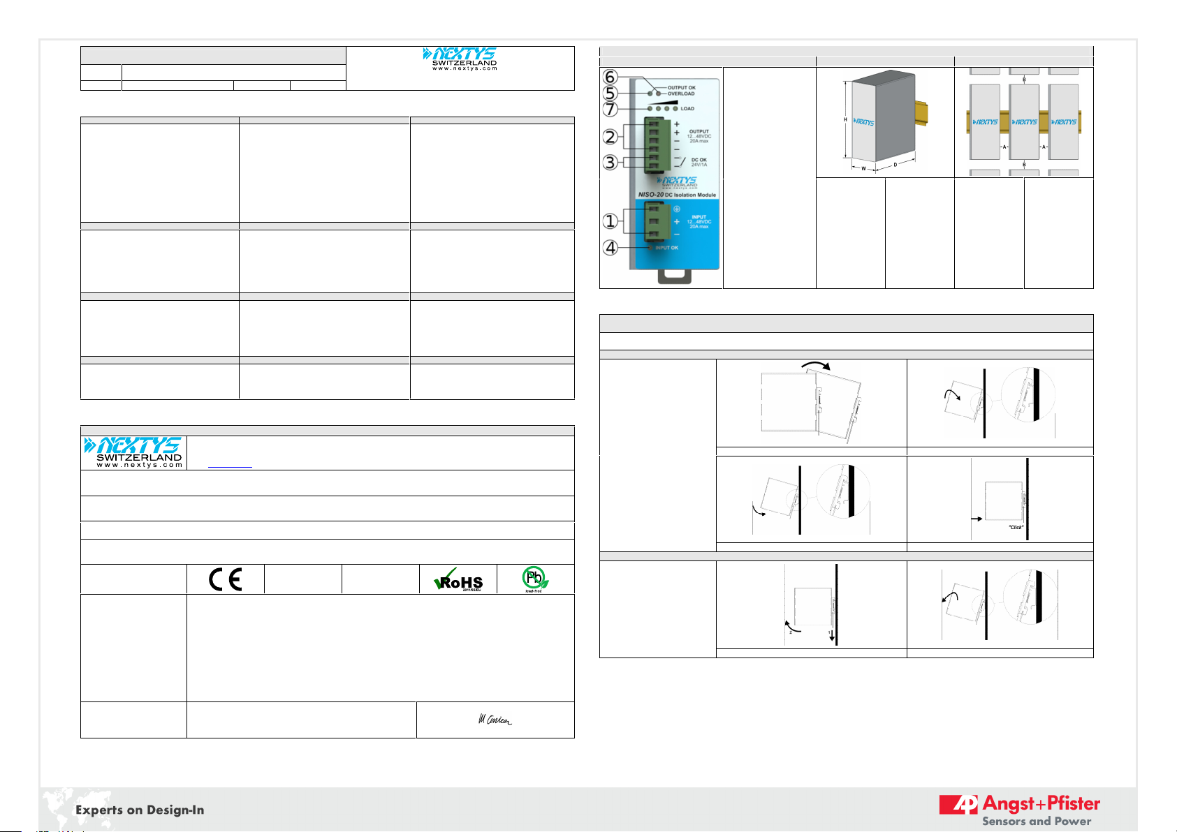
Connections and User interface
Fig.1
Fig.2
Fig.3
(1) DC input
(2) DC output (Load)
(3) Diagnostic Output
(dry contacts, NO)
(4) Green LED: Input OK
(5) Green LED: Output OK
(6) Red LED: Overload
(7) Yellow LEDs: Load status
bargraph display
Dimension
W
D
H
mm
54.0
115.0
110.0
Distance
A
B
mm
20
50
Mounting / Dismounting Instructions
Fig.4
For DIN rail mounting according to IEC 60715 TH35-7.5(-15). Mounting as shown in figure, with input terminals on lower side, with suitable cooling and maintaining a
proper distance between adjacent devices as specified in the User manual.
Mounting
1
2
1.Tilt the unit slightly backwards.
2.Fit the unit over the top edge of the
rail.
3.Slide it downward until it hits the
stop.
4.Press against the bottom for locking.
3
4
Dismounting
1.Pull down the slide clamp lever.
2.Tilt the unit upward.
3.Unhook the unit from the rail.
1 & 2
3
1 NISO-20_1680-21539-0003-E-1117
2
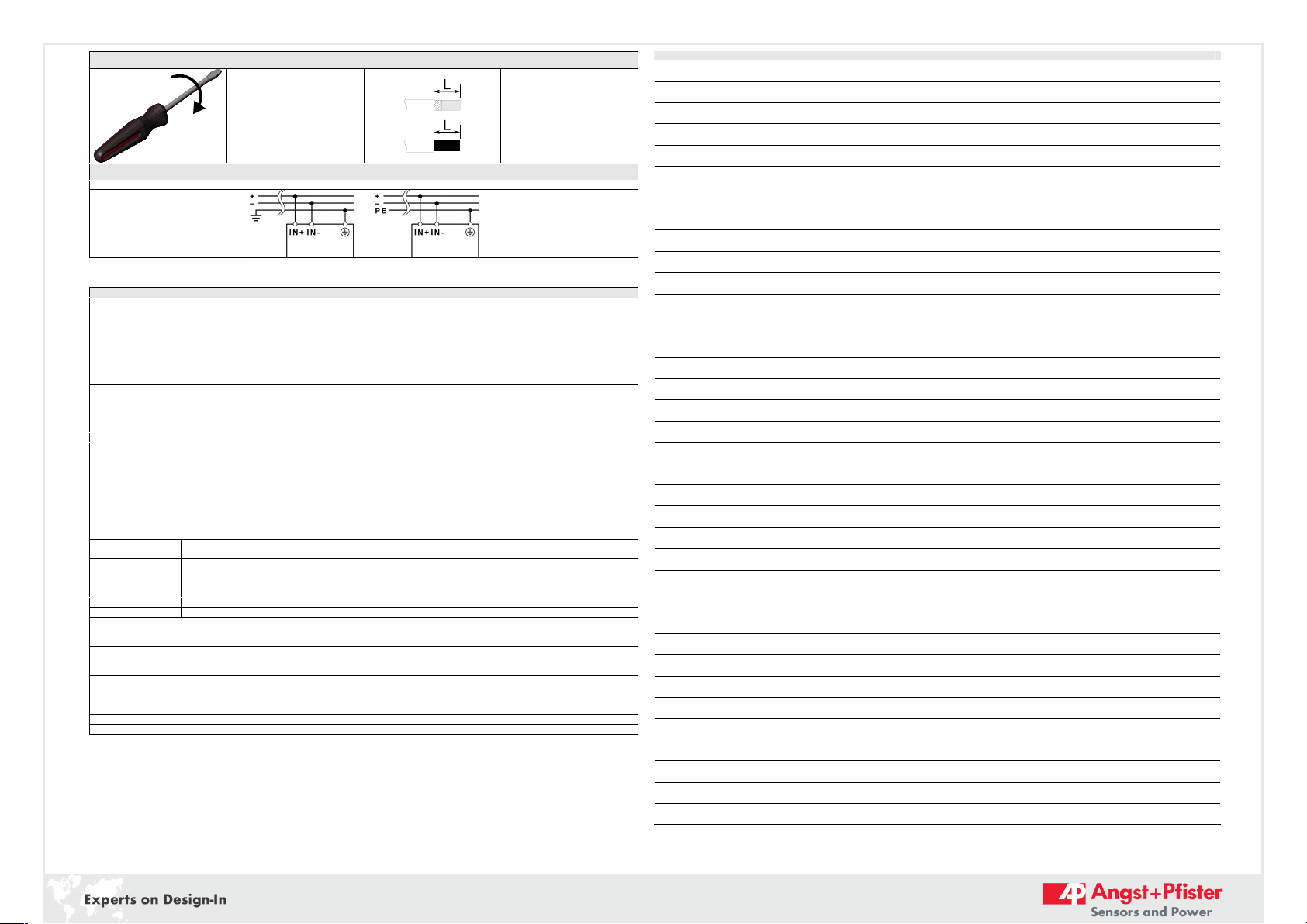
Recommended connecting cable
Fig.5
Recommended Tightening torque
0.5-0.6Nm
4.42-5.30 lbf in
Input / output connections
Solid: 2.5mm² / 12AWG
Stranded:1.5mm² / 12AWG
L: 6.0-7.5mm / 0.24-0.30in
Input connection
Fig.7
DC Line
INSTRUCTIONS
1) Description: NISO-20 can be supplied with any voltage between 10Vdc and 55Vdc, please respect the polarity. The output voltage will track the input voltage as
specified in the product datasheet.
To prevent damage in case of reverse polarity, the device is protected by an internal not replaceable fuse.
NISO-20 can be used in SELV and PELV circuits.
2) Installation: use DIN-rails according to EN 60715. Installation should be made vertically (see Fig.4). For better device stability fix the rail to the wall close to the point
where the device is to be mounted. In order to guarantee sufficient convection, we recommend observing a minimum distance to other modules (see Fig.3).
The device is provided with a thermal protection, a limited air flow can cause the thermal protection tripping.
The device automatically restarts after cooling.
To get normal operation reduce the temperature of the air surrounding the unit, increase the ventilation or reduce the load.
3) Connections: the device is equipped with pluggable screw terminals. To avoid sparks, do not connect or disconnect the connectors before having previously turned-off
input power and waited for capacitors discharge.
In order to comply with local certification, use appropriate copper cables of indicated cross section, designed for an operating temperatures of 60°C (for ambient <45°C)
and 75°C (for ambient < 60°C). Strip the connecting ends of the wires according to the indication on Fig.5 and ensure that all strands of a stranded wire enter the
terminal connection.
4) DC Input protection: NISO-20 is equipped with internal fuse, ratings of DC line protection devices must be coordinated with input current indicated on the data sheet.
5) Overload (OL) / short circuit (SC) / overvolatge (OVP) / overtemperature (OTP) protections: Hiccup auto-reset and over temperature protection.
OL exceeding the limits indicated on the data sheet, if applied to the device will make the output operate at on/off duty-cycle variable depending on OL value, air
temperature and device temperature.
Overload behaviour: Up to the overload limit there is no reduction of the output voltage. For output currents >Ilim the output is shut down and the Overload red LED
will be on.
Short circuit behaviour: The device enters into hiccup mode protecting the unit and the connected load.
Input/output overvoltage protection: the unit is protected against external overvoltage applied to the input; for input voltages greater than 62V the device will shut
down. In case of an internal failure, a double protection circuit switch off the output and avoid output voltage higher than 62V potentially dangerous for the supplied
devices.
6) Status Signals:
“Input OK” green LED:
on = the input voltage is present and within the product specified input voltage range
off = the input voltage is not present, check wiring
“Output OK” green LED:
on = the output voltage is present and within the product specified output voltage regulation range
off = output overload, direct short circuit on the output, input voltage not present, OVT/OVP shut down or device internal failure.
“OVERLOAD” red LED:
on = output overload, direct short circuit on the output, OVT/OVP shut down or device internal failure.
off = normal operation
“DC OK” relay contact:
Contact closes when the output voltage is present and within the product specified output voltage regulation range
“LOAD” LEDs bargraph
Each LED corresponds to about 4.5A of load current, all 4 LEDs are on when the output current exceeds about 18A
7) Redundant and parallel connection: For redundant connection, an external isolating diode must be used. Nextys OR20 or OR50 products are recommended.
Parallel connection for power increase can be achieved connecting the output of the devices in parallel. Please keep the length of the input and output cables of the 2
paralleled units the same length and cross section to achieve the best possible current balancing. Avoid exceeding 80% of the total available output current
10) Feeding DC motors: it is possible to feed DC motors considering that when a motor starts-up under effort its consumption is much higher than the nominal current
and it can trigger overcurrent protection.
NOTE: motors can generate high conducted noise on the DC line. Therefore it is not recommended to feed on the same line motors and equipment sensitive to noise.
11) Warranty: power supplies are guaranteed free from factory defects for the time specified in the “Sales Conditions”.
Failures caused by misuse, external and/or abnormal events (i.e. overvoltage, over temperatures) or non-respect of above parameters and standards, are not covered by
warranty.
Opening the housing of the product makes warranty to be no longer valid.
In order to improve the products Nextys SA reserves the right to change product specifications, ratings and data without previous advice.
NOTES
2 NISO-20_1680-21539-0003-E-1117

Headquarter Switzerland:
Angst+Pfister Sensors and Power AG
Thurgauerstrasse 66
CH-8050 Zurich
Phone +41 44 877 35 00
sensorsandpower@angst-pfister.com
Office Germany:
Angst+Pfister Sensors and Power Deutschland GmbH
Edisonstraße 16
D-85716 Unterschleißheim
Phone +49 89 374 288 87 0
sensorsandpower.de@angst-pfister.com
Power supplies
Sebastiano Leggio
Phone + 41 44 877 35 06
sebastiano.leggio@angst-pfister.com
Accelerometers
Sensor elements
Christoph Kleye
Phone +49 89 374 288 87 61
christoph.kleye@angst-pfister.com
Harald Thomas
Phone +49 89 374 288 87 23
harald.thomas@angst-pfister.com
Flow / Level / Medical products
Dr. Adriano Pittarelli
Phone +49 89 374 288 87 67
adriano.pittarelli@angst-pfister.com
Drive technology
CH Postcode 1000 – 4999 / AT / IT / FR
Christian Mohrenstecher
Phone +41 76 444 57 93
christian.mohrenstecher@angst-pfister.com
Gas sensors
Gas sensor modules
Dr. Thomas Clausen
Phone + 49 89 374 288 87 24
thomas.clausen@angst-pfister.com
Drive technology
CH Postcode 5000 – 9999 / DE
Roman Homa
Phone + 41 76 444 00 86
roman.homa@angst-pfister.com
Pressure Sensors
Load Cells
Philipp Kistler
Phone + 41 44 877 35 03
philipp.kistler@angst-pfister.com
Linear position sensors
Angle sensors
Eric Letsch
Phone + 41 44 877 35 14
eric.letsch@angst-pfister.com
Sales Other Countries / Product Management
Sales International Key Accounts
Peter Felder
Phone + 41 44 877 35 05
peter.felder@angst-pfister.com
Postcode 1000 – 2999
Christian Mohrenstecher
Phone +41 76 444 57 93
christian.mohrenstecher@angst-pfister.com
Sales Switzerland & Liechtenstein
Postcode 3000 – 9999
Basil Frei
Phone + 41 44 877 35 18
basil.frei@angst-pfister.com
Gas sensors and modules
Peter Felder
Phone +41 44 877 35 05
peter.felder@angst-pfister.com
Pressure sensors
Other products
Gerhard Vetter
Phone + 49 89 374 288 87 26
gerhard.vetter@angst-pfister.com
Sales Germany & Austria
Geometrical sensors
Other products
Kurt Stritzelberger
Phone + 49 89 374 288 87 22
kurt.stritzelberger@angst-pfister.com
We are here for you. Addresses and Contacts.
Experts on Design-In
for sensors and power solutions
Other nextys Control Unit manuals

Popular Control Unit manuals by other brands

SIGMA TEK
SIGMA TEK CP 102 instruction manual

Delta
Delta DVP04AD-H2 instruction sheet

Control Technologies
Control Technologies CTI 2554-A Installation and operation guide

GiBiDi
GiBiDi BE24 Instructions for installation

alphainnoTec
alphainnoTec RBE operating manual

B meters
B meters IWM-PL4 Quick user guide


