NFL 2 MINUTE DRILL User manual
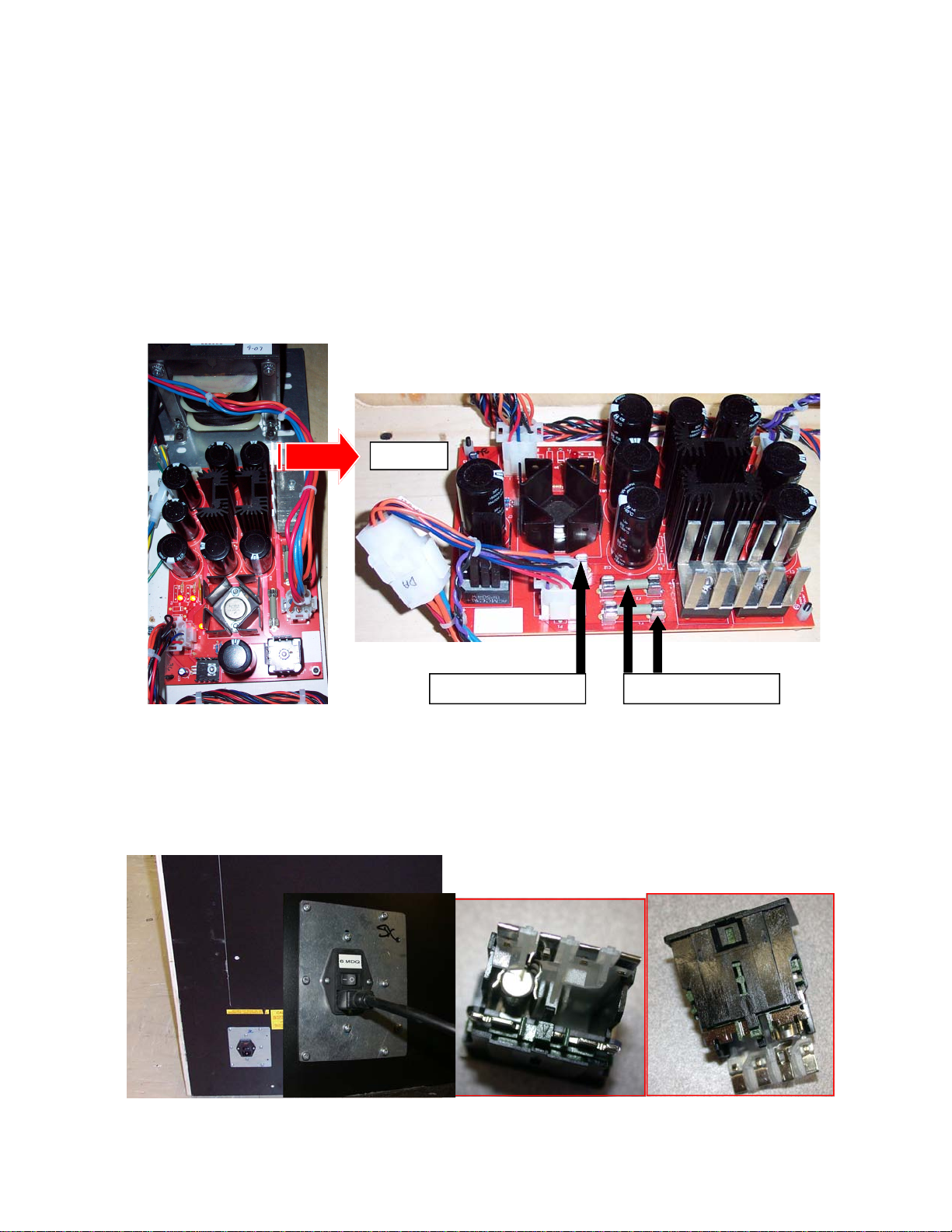
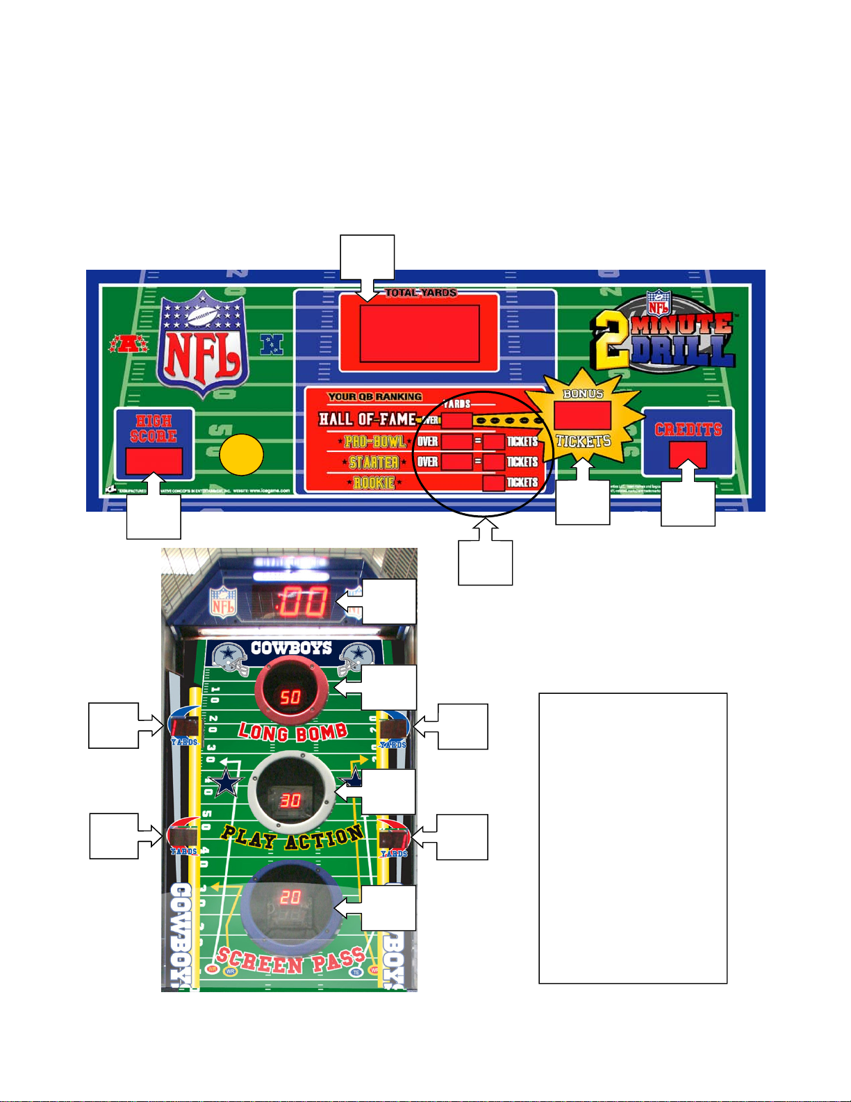
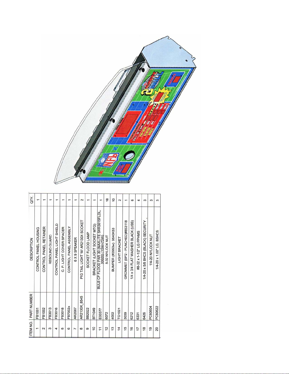

2
TABLE OF CONTENTS
SAFETY AND WARNINGS 3
• BeforeYouBegin
GAME SETUP AND FEATURES
• Introduction 4
• Game Play and Player Controls 4
• Assembly - see insert 4
• Programming - see insert 4
MAINTENANCE
• Power Supply & Transformer 5
• ACMainfuse 5
• General illumination 6
• LEDlights 6
• DisplayBoards 7
• Control Panel Assembly 8-15
• Target Marquee Assembly 16
• Target Cover Removal 17
• Target Motor Assembly 18-20
• Target Display board Assembly 21-23
• Conveyor Assembly Access 24
• Conveyer Assembly 25-26
• Playfield back door assembly 27
• Playfield target ring assembly 28-29
• Left Target bracket assembly 30
• Wiring harnesses 31-45
• Spare Parts List 46-48
WARRANTY INFORMATION 49-50
REV F 12/18/2008

3
BEFORE YOU BEGIN
WARNING: WHEN INSTALLING THIS GAME, A GROUNDED A.C. RECEPTACLE MUST BE
USED. FAILURE TO DO SO COULD RESULT IN INJURY TO YOURSELF OR OTHERS. FAIL-
URE TO USE A GROUNDED RECEPTACLE COULD ALSO CAUSE IMPROPER GAME OPERA-
TION, OR DAMAGE TO THE ELECTRONICS.
DO NOT DEFEAT OR REMOVE THE GROUNDING PRONG ON THE POWER CORD FOR
THE SAME REASON AS GIVEN ABOVE. USING AN IMPROPERLY GROUNDED GAME
COULD VOID YOUR WARRANTY.
HAVE A QUALIFIED ELECTRICIAN CHECK YOUR A.C. RECEPTACLE TO BE SURE THE
GROUND IS FUNCTIONING PROPERLY.
INSTALLATION
Please see assembly booklet insert for instructions on how to assembly the game.
1. Once the game is assembled plug the game into the A.C. outlet and turn on power to the
game. The switch for the game is located on a power module on the outside rear of the
game.
THIS GAME IS DESIGNED TO DISSIPATE STATIC ELECTRICITY THROUGH THE GROUNDING
PLANE OF THE GAME. IF THE A.C. GROUND DOES NOT WORK, THE GAME COULD DISCHARGE
STATIC ELECTRICITY THROUGH THE GAME CIRCUITRY, WHICH COULD CAUSE DAMAGE.
2. Make sure the game is level after installation. It is necessary to make sure the game is
level for safety concerns.
3. Check that the A.C. voltage rating on the back of the game matches the A.C. voltage of
your location.
THE POWER SUPPLY IS NOT VOLTAGE ADJUSTABLE. TO OPERATE THE GAME AT VOLTAGES
OTHER THAN THOSE IT WAS DESIGNED FOR. PLEASE CONTACT OUR SERVICE DEPARTMENT
FOR VOLTAGE CONVERSION INFORMATION.
WARNING
DO NOT remove any of the components on the main board (e.g. compact flash and
EPROMS) while the game is powered on. This may cause permanent damage to the
parts and the main board. Removing any main board component part while powered
on will void the warranty.
NOTE: THIS GAME IS INTENDED FOR INDOOR USE ONLY.
ON THE BACK PANEL OF THE GAME: WARNING: SHOCK HAZARD - DO NOT
OPEN. REFER SERVICING TO SERVICE PERSONNEL.
SAFETYAND WARNINGS

4
GAME SETUPAND FEATURES
Introduction
NFL TWO MINUTE DRILL™ is a revolutionary concept in Coin Operated football games. You
will see that this game includes many features which make it the obvious choice for your loca-
tion.
NFL™ incorporates both pop out targets as well as stationary targets that are user friendly and
realistic. Fun and easy to play for players of all ages, yet challenging enough for even the ex-
pert football players. Practice your football skills and try to better your last score or compete
against your friends.
CONTROL PANEL. Attractive LED displays are used to display all scoring and vital information
such as time, credits and high score. The control panel is laid out in a convenient user friendly
fashion, making it easy for players to operate.
HEAVY DUTY CONSTRUCTION is incorporated throughout the game by using only heavy
gage metals and plastics. The game can be assembled and disassembled many times without
any harm to the game. You will appreciate this feature if you move your games often.
HIGH TECH GAME ELECTRONICS. Solid state electronics are used throughout the game for
their rugged reliability as well as making it virtually impossible to connect harnessing the wrong
way. Heavy duty optical sensors are used throughout.
Digital sound effects are used for optimum dependability. Over twenty sound effects are incor-
porated into the sound effect circuitry. The game electronics have been highly integrated into
the Main PC Board assembly, making it easy to repair games. The game has a full feature self-
test system to make troubleshooting easier.
OPTIONS. A ticket dispenser and/or a dollar bill acceptor can be ordered with your game.
Game Play
NFL™ is an interactive coin operated amusement game.
Linking is a popular option used in locations where more than one game is to be
used. The games are linked with the marquee option to add direct head to head action
between the game players. This option is built into each main PC board but requires
the marquee to activate, and it is as easy as connecting a phone cord and setting a
number between 1-9 on the main circuit board.
Assembly- See insert.
Programming- See insert.

5
Maintenance
Power Supply & Transformer
The power supply and transformer are located in the back of the game. To access
them, you must open the bottom back access door and located on the left is the power
assembly. See pictures below
F1 & F2 = 8 amp slow
F3 = 4 amp slow
DA2001X
AC Main Power Fuse
Located in the power module is a 3 amp slow blow fuse. To check or replace the fuse
pull the tab with the label out. There is only one fuse installed. See diagram below.

6
Maintenance
General illumination
Location of bulbs
There are two 8545’s (Compact fluorescent bulbs) located in the control panel, one
E00377 (Flood Bulb) and located above the Playfield area is one 8312 (PLL 18 bulb).
(1) 8312 (PLL)
(1) E00377 (Flood)
(2) 8545 (Curly)
Control panel bulbs
To access the three bulbs located in the control panel you will need to remove the
bracket holding the control panel. Use a 5/32 Allen and 7/16 wrench to remove the 3
bolts holding the top bracket of the control panel. See page 13 for bracket diagram
and see pages 8 through 12 for assembly diagrams of the control panel.
Playfield bulb
Open the top back door and remove the #2 square head screws that hold the upper
cover plate. You can now access the top PLL bulb. It is also possible to access the
bulb from the front if access to the back is limited. See diagram on page 14.
LED Lights
There are two LED strips to illuminate the word GAME CLOCK located at the top of the
playfield in the marquee. You will need to remove the front marquee to replacement
the LED strips. See the assembly diagram on page 14 for removal. There are also
four strips located in the control panel to illuminate the player’s ranking. See diagram
on page 13 for access. The LED Strips located in the target area are part of the dis-
play assemblies and cannot be replaced alone. See display location on the next
page.

7
ICE part numbers
[1] CB2232X
[2] CB2233X
[3] FB2032X
[4] FB2033X
[5] FB2035RX
[6] FB2035WX
[7] FB2035BX
[8] DA2133X
Display Board locations
Control panel display boards are located below. FB2032X is a display that includes
six display boards and five mini footballs. See picture below.
Maintenance
1 1
1
3
START
2
5
6
7
4
8
8
8
8

8
Maintenance
Control Panel Assembly
FB1001X

9
Maintenance
Control Panel Assembly
FB1001X

10
Maintenance
Control Panel Assembly
FB1001X

11
Maintenance
Control Panel Assembly
FB1001X

12
Maintenance
Control Panel Assembly
FB1001X

13
Maintenance
Control Panel Assembly
FB1001X

14

15

16
Maintenance
Marquee light box assembly

17
Maintenance
Target Covers
To access the target motors you will need to remove the display housing. You also will
need to ensure the targets are protruding out as shown below. Unlatch the harness
clamps located in the back side of the game first. Remove the four mounting screws at
the bottom back of the game in order to gain access to remove the back door. This will
allow you enough slack in the wires to lift the covers off and lay them on their side. It is
not necessary to fully remove the target covers to access the target motors. Only re-
move the four lower bolts and loosen the two top bolts. Slide the cover up until the top
bolts heads can slide out the slotted holes. The diagram shows the location of the
bolts. Bolt locations are shown on two different covers but exists on both sides of the
cover.
Remove
Remove
Loosen
only
Loosen
only
Remove
Remove

18
Maintenance
Target Motor Assembly
FB1031X (assembled for the left side)
FB1031AX (assembled for the right side)

19
Maintenance
Target Motor Assembly
FB1031X

20
Maintenance
Target Motor Assembly
FB1031X
Table of contents
Popular Arcade Game Machine manuals by other brands

Atari
Atari STEEPLECHASE OPERATION, MAINTENANCE & SERVICE MANUAL

Pop-A-Shot
Pop-A-Shot CLASSIC DUAL owner's manual

Hathaway
Hathaway BLUERIDGE BG50381 Assembly instructions

Universal Space
Universal Space Squirt A Gator Operation manual

Atari
Atari PONG 4P Operation manual

EZPinball
EZPinball EZStern-01 Assembly Instructions & Parts List

Tecway
Tecway Captain Jack Operation manual

Incredible Technologies
Incredible Technologies LoonyTIX install guide

Bay Tek Games
Bay Tek Games PERFECTION Service manual

MD SPORTS
MD SPORTS CBF056 018M Assembly instructions

MD SPORTS
MD SPORTS 1614823 Assembly instructions

MD SPORTS
MD SPORTS AC220Y19001 Assembly instructions