NI Ettus USRP X410 User manual

GETTING STARTED GUIDE
Ettus USRP X410
1 MHz to 7.2 GHz, 400 MHz Bandwidth, GPS-Disciplined OCXO,
USRP Software Defined Radio Device
This document explains how to install, configure, and test the Ettus USRP X410 Software
Defined Radio Device.
The Ettus USRP X410 can send and/or receive signals for use in various communications
applications. You can use NI-USRP or the USRP Hardware Driver (UHD) to program the
device.
Contents
Unpacking the Kit..................................................................................................................... 1
Verifying the Kit Contents................................................................................................ 2
Additional Items for Device Set-Up......................................................................................... 2
Verifying the System Requirements..........................................................................................3
Ettus USRP X410 Front Panel, Back Panel, and LEDs ...........................................................3
Selecting Your Driver................................................................................................................6
NI-USRP................................................................................................................................... 8
Setting Up the Device....................................................................................................... 8
Installing the Software.................................................................................................... 11
Programming the Device.................................................................................................11
UHD........................................................................................................................................ 16
Setting Up the Device..................................................................................................... 16
Installing the Software.................................................................................................... 18
Programming the Device................................................................................................ 18
NI Services..............................................................................................................................19
Unpacking the Kit
Notice To prevent electrostatic discharge (ESD) from damaging the device, ground
yourself using a grounding strap or by holding a grounded object, such as your
computer chassis.
1. Touch the antistatic package to a metal part of the computer chassis.
2. Remove the device from the package and inspect the device for loose components or any
other sign of damage.
Notice Never touch the exposed pins of connectors.

Note Do not install a device if it appears damaged in any way.
3. Unpack any other items and documentation from the kit.
Store the device in the antistatic package when the device is not in use.
Verifying the Kit Contents
Figure 1. Kit Contents
5 6
TX/RX 0 TX/RX 0
TX OUTPUT MAX +15 dBm, RX INPUT MAX +20 dBm, ALL RF PORTS 50 Ω
RX 1 RX 1 DB 1DB 0
RF 0 RF 1
TX/RX 0 TX/RX 0
TX OUTPUT MAX +15 dBm, RX INPUT MAX +20 dBm, ALL RF PORTS 50 Ω
RX 1 RX 1
RF 0 RF 1
GPIO 0
Ettus USRP
X410
3.3 VDC MAX
GPIO 1
3.3 VDC MAX
ESD
SENSITIVE
ESD
SENSITIVE
2-Channel RF
1 MHz to 7.2 GHz
Transceiver
400 MHz BW
2-Channel RF
1 MHz to 7.2 GHz
Transceiver
400 MHz BW
1
2
4
3
1. Ettus USRP X410
2. CAT 5E Ethernet Cable
3. USB-A (m) to USB-C (m) with Jack Screw Cable
4. Power Supply
5. Ettus USRP X410 Documentation Note
6. Ettus USRP X410 Safety, Environmental, and
Regulatory Information
Additional Items for Device Set-Up
• Cables
– PCIe/MXI express cable
– QSFP28 to QSFP28 Ethernet cable
– QSFP28 to 4xSFP28 Ethernet breakout cable
– SMA (m)-to-SMA (m) cable
• Host PC
• PXI Express chassis
• PXIe-8881 or other PXI controller
• PXIe-8394 or other PXI bus extension module
• PCIe-8398 or other device for PXI remote control
2| ni.com | Ettus USRP X410 Getting Started Guide

• 10 Gb Ethernet network card or 100 Gb Ethernet network card
Tip NI recommends using an Ethernet network card available in connectivity
kits sold on www.ettus.com and ni.com.
• 30 dB attenuator
Note If you directly connect or cable a signal generator to your device, or if you
connect multiple devices together, use an attenuator to avoid damaging the device.
Verifying the System Requirements
To use NI-USRP or UHD, your system must meet certain requirements.
Refer to your driver's readme for more information about minimum system requirements,
recommended system, and supported application development environments (ADEs). The NI-
USRP Readme is available online on the driver software download page or at ni.com/manuals.
The UHD Readme is available on The USRP Hardware Driver Repository.
Ettus USRP X410 Front Panel, Back Panel, and
LEDs
Figure 2. Front Panel
TX/RX 0 TX/RX 0
TX OUTPUT MAX +15 dBm, RX INPUT MAX +20 dBm, ALL RF PORTS 50 Ω
RX 1 RX 1 DB 1DB 0
RF 0 RF 1
TX/RX 0 TX/RX 0
TX OUTPUT MAX +15 dBm, RX INPUT MAX +20 dBm, ALL RF PORTS 50 Ω
RX 1 RX 1
RF 0 RF 1
GPIO 0
Ettus USRP
X410
3.3 VDC MAX
GPIO 1
3.3 VDC MAX
ESD
SENSITIVE
ESD
SENSITIVE
2-Channel RF
1 MHz to 7.2 GHz
Transceiver
400 MHz BW
2-Channel RF
1 MHz to 7.2 GHz
Transceiver
400 MHz BW
Ettus USRP X410 Getting Started Guide | © National Instruments Corporation | 3

Table 1. Front Panel Connector Descriptions
Connector Description
DB 0, DB 1 RF 0 TX/RX 0 Output and input terminal for the RF signal. TX/RX 0 is an
SMA (f) connector with an impedance of 50 Ω and is a
single-ended input or output channel.
RX 1 Input terminal for the RF signal. RX 1 is an SMA (f)
connector with an impedance of 50 Ω and is a single-ended
input channel.
RF 1 TX/RX 0 Output and input terminal for the RF signal. TX/RX 0 is an
SMA (f) connector with an impedance of 50 Ω and is a
single-ended input or output channel.
RX 1 Input terminal for the RF signal. RX 1 is an SMA (f)
connector with an impedance of 50 Ω and is a single-ended
input channel.
GPIO 0, GPIO 1 General Purpose Input/Output (GPIO) digital terminals. GPIO
0 and GPIO 1 are HDMI Type-A connectors. Output voltage
can be configured per individual connector, either 1.8 V
(default), 2.5 V, or 3.3 V.
Figure 3. Back Panel
CONSOLE ETHERNET
POWER
USB to PS
GPS ANT
IN –15 dBm MAX
OUT 3.3 V DC
PPS IN
0
0
QSFP28iPass+ zHD
1
1
3.3 V
–3 V MIN, 5 V MAX
TRIG IN/OUT
3.3 V
–2 V MIN, 5 V MAX
REF IN
+15 dBm MAX 10/100/1000
12 V DC 16A MAX
RESET
LED 1
LED 0
PWR
LED 2
JTAG
XXXXXXX–XX AIRFLOW:
XXXXXXX EXHAUST
Table 2. Back Panel Connector Descriptions
Connector Description
iPass+ zHD Provides a PCIe connection to a host PC for using the device with
LabVIEW FPGA. Port 0 can be used alone for a Gen 3x4 connection.
Port 0 and Port 1 can be used together for a Gen 3x8 connection.
QSFP28 Supports multiple configurations for streaming high-speed, low-latency
data, depending on the FPGA image loaded. Designed for speeds of up to
25 Gbps per lane with 4 lanes in each connector and a bandwidth of up to
100 Gbps per connector.
4| ni.com | Ettus USRP X410 Getting Started Guide

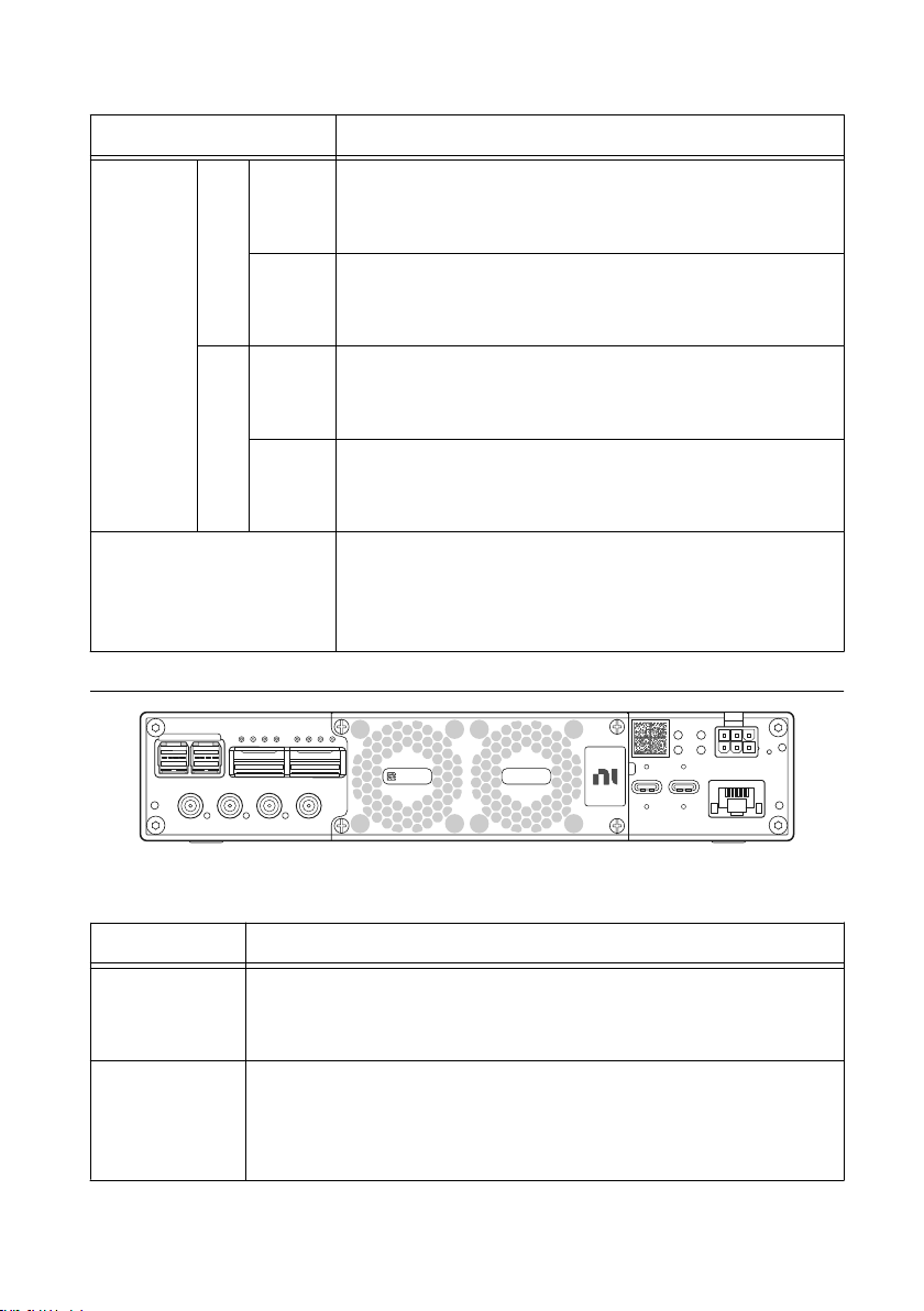
Table 2. Back Panel Connector Descriptions (Continued)
Connector Description
GPS ANT Input terminal for the GPS antenna signal. GPS ANT is an SMA (f)
connector with a maximum input power of -15 dBm and an output of
3.3 V DC to power an active antenna.
Notice Do not terminate the GPS ANT port if you do not use
it.
REF IN Input terminal for an external reference signal to synchronize the device.
REF IN is an SMA (f) connector with an impedance of 50 Ω, and it is a
single-ended reference input. REF IN accepts a 10 MHz signal with a
minimum input power of 0 dBm (0.632 V pk-pk) and a maximum input
power of 15 dBm (3.56 V pk-pk) for a square wave or sine wave.
PPS IN Input terminal for PPS timing reference. PPS IN is an SMA (f) connector
with an impedance of 50 Ω and is a single-ended input channel. PPS IN
accepts 0 V to 3.3 V TTL and 0 V to 5 V TTL signals.
TRIG IN/OUT Input/Output trigger terminal. This port can be used to output the PPS
timing reference. TRIG IN/OUT is an SMA (f) connector with an
impedance of 50 Ω and is a single-ended port. The output voltage is 0 V
to 3.3 V TTL. You can also use this port as a triggered output
(TRIG OUT) that you program in LabVIEW FPGA.
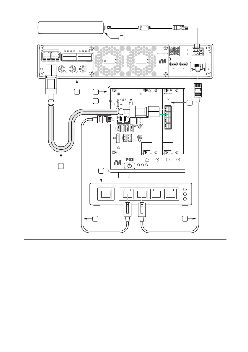
POWER Input that accepts a 12 V ± 5%, 16 A external DC power connector.
CONSOLE JTAG A USB Type-C port that connects the host computer to the device FPGA
for development and debugging. This port provides access to the FPGA
JTAG, the PS serial console, and the SCU serial console. It should be
used with the 115200 baud, 8 data bits, 1 stop bit, no parity. LabVIEW
FPGA does not currently support configuring or programming the device
FPGA using the JTAG connector.
USB to PS A USB Type-C 2.0 port that can be used to connect peripheral devices to
the processing system (PS), such as a USB mass storage device. May also
be used to complete functions such as writing a new file system to the
internal storage.
ETHERNET 1 Gigabit Ethernet Connection that interfaces with the onboard PS. Can
be used to connect to the PS through SSH. Can be used for UHD
management traffic in Network Mode. By default, the 1 Gb Ethernet
connection is configured to use a DHCP assigned IP address.
Ettus USRP X410 Getting Started Guide | © National Instruments Corporation | 5

Table 3. Back Panel LEDs
LED Description Color State Indication
LED 0 Indicates the status of the PS. — OFF The processor is powered off.
Green Blinking The frequency of blinks is
proportional to the CPU load.
Solid The processor is powered on.
LED 1 Indicates the status of the FPGA/
Programmable Logic (PL).
— OFF The FPGA/PL is not loaded.
Green Solid The FPGA/PL is loaded.
LED 2 Indicates the status of the
onboard eMMC storage activity.
— OFF The eMMC is idle.
Green Blinking There is read or write activity
on the eMMC.
Solid There is read or write activity
on the eMMC.
PWR Indicates the power state of the
device.
— OFF The device is powered off.
Green Solid The device is powered on and
the power is good.
Red Solid The device is in a power error
state.
Amber Solid The device is powered off and
the power is good.
Note The previous table describes default LED settings. LED functionality can be
changed in software.
Selecting Your Driver
Both the USRP Hardware Driver™ (UHD) software API and NI-USRP driver support
application development using the Ettus USRP X410.
Select the driver that best suits your application.
6| ni.com | Ettus USRP X410 Getting Started Guide

Table 4. NI-USRP and UHD Comparison
Feature NI-USRP UHD
Distribution Form Closed-Source Open-Source
Host OS Windows
NI Linux Real-Time for PXI
Windows
Linux
Mac OS
Host ADE LabVIEW GNU Radio
C/C++
MATLAB/Simulink
Python
FPGA Development Environment LabVIEW FPGA Module VHDL
Verilog
HDL Coder
RFNoC
Earliest Version with Ettus USRP X410
Support
21.0 4.1.0.2
Streaming/Host Interface Support Cabled PCIe/MXI Express110 Gb Ethernet
100 Gb Ethernet
NI-USRP utilizes portions of UHD and allows for programming in LabVIEW, NI’s flagship
intuitive development environment. The abstracted design environment helps accelerate the
design of wireless systems and makes FPGA programming accessible to those without HDL
design expertise. Using LabVIEW, you have the option to program the FPGA and host in a
single development environment. Users have the option to customize the FPGA when using
NI-USRP.
UHD uses a common, open-source software interface that increases code portability, allowing
applications to transition to other USRP SDR platforms when development requirements
expand or new platforms are available. UHD offers cross-platform support for multiple
industry-standard development environments and frameworks, including GNU Radio and
MATLAB/Simulink.
1Also requires a 1 Gb Ethernet connection to the device.
Ettus USRP X410 Getting Started Guide | © National Instruments Corporation | 7

Refer to the following sections that apply to the driver of your choice to continue setting up
your device.
NI-USRP
Setting Up the Device
Ensure that all of your hardware components are powered off before installing.
1. Verify that you have all items included in your device kit and the following additional
items.
• PXIe chassis
• PXIe-8881 or other PXI controller
• PXIe-8394 or other PXI bus extension module
• Network switch
• PCIe/MXI express cable
• CAT 5E Ethernet cable
Note Alternative configurations are possible. For example, the Ettus USRP
X410 can also be set up with a host PC and PCIe-8398 instead of the PXI
chassis, PXI controller, and PXI bus extension module.
2. Set all items on a flat surface near power outlets and a modem or router.
3. Follow the instructions included with your network switch to connect it to a modem or
router.
4. Connect any additional attachments required for your project to the front panel terminals
of the Ettus USRP X410.
Installing the Modules into the Chassis
Install the PXIe-8881 or other PXI controller in the first slot of your chassis and then the
PXIe-8394 or other PXI bus extension module in a slot to the right of the controller by
completing the following steps.
1. Ensure the AC power source is connected to the chassis before installing the module.
The AC power cord grounds the chassis and protects it from electrical damage while you
install the module.
2. Power off the chassis.
3. Inspect the slot pins on the chassis backplane for any bends or damage prior to
installation. Do not install a module if the backplane is damaged.
4. Remove the black plastic covers from all the captive screws on the module front panel.
5. Identify a supported slot in the chassis. Refer to the following table to determine which
slot types the PXI controller and PXI bus extension module are compatible with. Symbols
along the bottom of the chassis indicate the slot type.
8| ni.com | Ettus USRP X410 Getting Started Guide

Table 5. Slot Type Compatibility
NI PXI Express Product
PXI Express Chassis
Controller Peripheral Hybrid
H
PXI controller ✓— —
PXI bus extension module — ✓ ✓
6. Touch any metal part of the chassis to discharge static electricity.
7. Ensure that the ejector handle is in the downward (unlatched) position.
8. Place the module edges into the module guides at the top and bottom of the chassis. Slide
the module into the slot until it is fully inserted.
Figure 4. Module Installation
2
1
3
1. Chassis
2. Hardware module
3. Ejector handle in downward (unlatched position)
9. Latch the module in place by pulling up on the ejector handle.
10. Secure the module front panel to the chassis using the front-panel mounting screws.
Note Tightening the top and bottom mounting screws increases mechanical
stability and also electrically connects the front panel to the chassis, which can
improve the signal quality and electromagnetic performance.
11. Complete steps 5 through 10 for the PXI controller and PXI bus extension module.
12. Cover all empty slots using either filler panels (standard or EMC) or slot blockers with
filler panels, depending on your application.
Note For more information about installing slot blockers and filler panels, go
to ni.com/r/pxiblocker.
Connecting the Device (NI-USRP)
The following describes one hardware configuration option. Other configurations are possible.
Connect your hardware as shown in the following diagram.
Ettus USRP X410 Getting Started Guide | © National Instruments Corporation | 9

CONSOLE ETHERNET
POWER
USB to PS
GPS ANT
IN –15 dBm MAX
OUT 3.3 V DC
PPS IN
0
0
QSFP28iPass+ zHD
1
1
3.3 V
–3 V MIN, 5 V MAX
TRIG IN/OUT
3.3 V
–2 V MIN, 5 V MAX
REF IN
+15 dBm MAX 10/100/1000
12 V DC 16A MAX
RESET
LED 1
LED 0
PWR
LED 2
JTAG
XXXXXXX–XX AIRFLOW:
XXXXXXX EXHAUST
PWR/
LINK
4
3
2
1
PXIe-8394
MXI-Express
PS TEMP FANS
PXIe-8881
Embedded Controller
USER1
USER2
DRIVE
PWR OK/
FAULT
TRIG
RESET
10/100
/1000
GPIB
10/100
/1000
ACT/
LINK
ACT/
LINK
01
1
2
1
8
6
5
7
34
2
7
1. Ettus USRP X410
2. PXIe Chassis
3. PXIe-8881 or other PXI Controller
4. PXIe-8394 or other PXI Bus Extension Module
5. Network Switch (optional)
6. PCIe/MXI Express Cable
7. CAT 5E Ethernet Cable
8. Power Supply
10 | ni.com | Ettus USRP X410 Getting Started Guide

Table 6. Ettus USRP X410 Connections (NI-USRP)
Connector Type Connection 1 Connection 2 Label in
Figure
PCIe/MXI Express
Cable
Ettus USRP X410,
iPass+ zHD Ports
PXI Bus Extension
Module, MXI-Express
Gen-3 x16 Ports
6
CAT 5E Ethernet
Cable
PXI Controller,
10/100/1000 LAN Port
Network Switch 7
CAT 5E Ethernet
Cable
Network Switch Ettus USRP X410
ETHERNET Port
7
Power Supply ― Ettus USRP X410
POWER Port
8
Note If you choose not to use the optional network switch, use one CAT 5E
Ethernet cable to connect the Ettus USRP X410 to the PXI Controller. This hardware
setup requires additional configuration in software. Either set a DHCP server on the
PXI controller or set a static IP address on the Ettus USRP X410.
Powering on the Device
1. Connect the power supply to the Ettus USRP X410.
2. Plug the power supply into a wall outlet. Press the power button on the front of your
device.
3. Power on the chassis and network switch.
Installing the Software
You must be an Administrator to install NI software on your computer.
1. Install your ADE, LabVIEW.
2. Download the driver software installer from ni.com/downloads.
NI Package Manager downloads with the driver software to handle the installation. Refer
to the NI Package Manager Manual for more information about installing, removing, and
upgrading NI software using NI Package Manager.
3. Follow the instructions in the installation prompts.
Note Windows users may see access and security messages during
installation. Accept the prompts to complete the installation.
4. When the installer completes, select Restart in the dialog box that prompts you to restart,
shut down, or restart later.
Programming the Device
You can use the NI-USRP instrument driver to create communications applications for the
Ettus USRP X410.
Ettus USRP X410 Getting Started Guide | © National Instruments Corporation | 11

Updating the File System
A file system update is required to use your device with NI-USRP.
Use the Windows Command Prompt to establish an SSH connection and update your file
system, then use the NI-USRP Configuration Utility to write the new FPGA image to your
device.
1. On your host PC running Windows 10 version 1809 or later, select Start » Windows
System » Command Prompt to open the Windows Command Prompt.
2. To print information about your device, run the commands
cd “C:\Program Files (x86)\National Instruments\NI-USRP\utilities”
then uhd_find_devices.exe.
Information about your device is output in the command prompt window, as shown in the
following example.
Device Address:
serial: 32190B5
addr: 10.89.8.21
claimed: False
fpga: X4_200
mgmt_addr: 10.89.8.21
product: x410
type: x4xx
Use the combination of numbers and letters following serial: as your unique serial
number. The serial number is also printed on a label on the bottom of your device.
Use the IP address following addr: to identify your device in step 7.
3. Use an SSH connection to access your device’s management console.
a) To open an SSH connection, use your unique serial number to run the command
ssh root@ni-x4xx-<serial>
Running this command opens a session with the username root and a blank
password.
b) Type yes and press <Enter> if you are prompted to select whether you want to
continue connecting.
The first time you successfully connect, the following warning is output.
Warning: permanently added 'ni-x4xx-<serial>' (ECDSA) to
the list of known hosts.
root@ni-x4xx-<serial>:~#
c) Type exit and press <Enter> to exit the SSH connection.
4. Transfer the embedded file system image to the device by running the command scp
"C:\Program Files (x86)\National Instruments\NI-USRP
12 | ni.com | Ettus USRP X410 Getting Started Guide

\filesystems\usrp_x4xx_fs_v4.1.0.4.mender" root@ni-x4xx-
<serial>:/home/root/
Note You may need to update the mender version referenced in this command
depending on the version in use.
5. Update the file system image on your device.
a) To open a new SSH connection, run the command
ssh root@ni-x4xx-<serial>.
b) Run the command
mender install /home/root/usrp_x4xx_fs_v4.1.0.4.mender.
Note The required command may differ depending on the mender
version installed.
The output may take several minutes to print.
c) After the output from the previous command has printed, type reboot and press
<Enter> to restart your device.
Your SSH session closes. The restart should take less than three minutes.
6. Access the device and switch to a new embedded file system image.
a) Run the command uhd_find_devices.exe.
Information about your device is output in the command prompt window. If it does
not appear, wait three minutes to ensure that the device has restarted and run the
command again.
b) To update the SSH security fingerprint of your device, run the command
ssh-keygen -R ni-x4xx-<serial>.
c) To reconnect to the management console, run the command
ssh root@ni-x4xx-<serial>.
d) Type yes and press <Enter> if you are asked whether you want to continue
connecting.
e) To verify that you are using the updated file system, run the command
cat /etc/mender/artifact_info.
The resulting output contains the version of your file system:
artifact_name=<version>_x4xx. If you have successfully updated your file
system, the version in the output should be the same as the mender version
referenced in step 4.
f) To commit the update and use the new file system, run the command
mender commit.
7. Use NI-USRP Configuration Utility to write the new FPGA image to your device.
a) Select Start »All Programs »National Instruments »NI-USRP Configuration
Utility to open NI-USRP Configuration Utility.
b) Select the N2xx/NI-29xx/X410 Image Updater tab of the utility.
Your device should appear in the Device ID column. Verify that the IP address
matches the IP address for your device shown in step 2.
c) Select your device.
Ettus USRP X410 Getting Started Guide | © National Instruments Corporation | 13

The FPGA Image field should populate.
d) Click WRITE IMAGES and select OK when prompted.
If you are successful, a confirmation will appear on screen.
e) Exit the NI-USRP Configuration Utility and restart your host PC.
Configuring the Ettus USRP X410 in MAX
Use Measurement & Automation Explorer (MAX) to configure your NI hardware. MAX
informs other programs about which NI hardware products are in the system and how they are
configured. MAX is automatically installed with NI-USRP.
1. Launch MAX.
2. In the configuration tree, expand Devices and Interfaces to see the list of installed NI
hardware.
Installed modules appear under the name of their associated chassis.
3. Expand your Chassis tree item.
MAX lists all modules installed in the chassis. Your default names may vary.
Note If you do not see your module listed, press <F5> to refresh the list of
installed modules. If the module is still not listed, power off the system, ensure
the module is correctly installed, and restart.
4. Record the identifier MAX assigns to the hardware. Use this identifier to reference the
Ettus USRP X410.
Verifying the Device Connection Using LabVIEW
Perform a loopback test to confirm that the device transmits and receives signals and is
connected correctly to the host computer.
1. Attach the 30 dB attenuator to one end of the SMA (m)-to-SMA (m) cable.
2. Connect the 30 dB attenuator to the RF 0 - TX/RX 0 connector on the front panel of the
USRP device and connect the other end of the SMA (m)-to-SMA (m) cable to the
RF 0 - RX 1 port.
14 | ni.com | Ettus USRP X410 Getting Started Guide

3. On the host computer, navigate to <NIDIR> »National Instruments »LabVIEW
<Year> »examples »instr »niUSRP .
4. Open the niUSRP EX Tx Continuous Async example VI.
a) Change the Device Name to the default name listed for you device in MAX.
b) Change the Antenna to TX/RX0.
c) Run the VI.
If the device is transmitting signals, the I/Q graph displays I and Q waveforms.
5. Open the niUSRP EX Rx Continuous Async example VI and run it.
a) Change the Device Name to the default name listed for you device in MAX.
b) Change the Antenna to RX1.
c) Run the VI.
If the device is transmitting signals, the I/Q graph displays I and Q waveforms.
NI-USRP Examples
NI-USRP includes several example applications that serve as interactive tools, programming
models, and building blocks in your own applications.
NI-USRP examples are available in the following locations.
• From the Start menu at Start »All Programs »National Instruments »NI-USRP »
Examples
• From the LabVIEW Functions palette at Instrument I/O »Instrument Drivers »NI-
USRP »Examples
Note You can access additional examples from the Code Sharing Community at
ni.com/usrp.
Note The NI Example Finder does not include NI-USRP examples.
Troubleshooting
If an issue persists after you complete a troubleshooting procedure, search our KnowledgeBase
for additional information our technical support engineers create as they answer common user
questions and resolve unexpected issues.
Why Can't I Open a Session to My Ettus USRP X410 with LabVIEW?
Ensure that PCIe and Ethernet connections are available between the computer and the X410:
• Verify that the PCIe connection is available by checking that the device is listed in MAX.
• Verify that the Ethernet is available. On your host PC, open Windows Command prompt
and run uhd_find_devices.exe. If the device does not show up in the output, the
device is not in communication with the host PC. If the X410 is listed but part of the
output reads Reachable: no, then your firewall is blocking some communication with
the device. If there are no problems indicated by the output, run uhd_usrp_probe --
args addr=<device IP address> to test connectivity over Ethernet. If the
Ettus USRP X410 Getting Started Guide | © National Instruments Corporation | 15

command runs successfully but LabVIEW still cannot connect, load a different bitfile on
the device.
Why Can't I Detect My Device in LabVIEW?
Complete one or more of the following options to detect your device in LabVIEW:
• Ensure that the device has been updated with an NI-USRP compatible FPGA.
• Ensure that the device is powered on and has a valid IP address.
• Refer to the NI-USRP Readme to verify that your version of the NI-USRP instrument
driver supports the Ettus USRP X410.
UHD
Setting Up the Device
Ensure that all of your hardware components are powered off before installing.
1. Verify that you have all items included in your device kit and the following additional
items.
• Host PC
• Network switch
• CAT 5E Ethernet Cable (optional)
• One of the following:
– QSFP28 to QSFP28 Ethernet cable and 100 Gb Ethernet network card
– QSFP28 to 4xSFP28 Ethernet breakout cable and 10 Gb Ethernet network card
2. Set all items on a flat surface near power outlets and a modem or router.
3. Follow the instructions included with your network switch to connect it to a modem or
router.
4. Follow the instructions included with your host PC to connect it to power and complete
your computer setup.
5. Connect any additional attachments required for your project to the front panel terminals
of the Ettus USRP X410.
Connecting the Device (UHD)
The following describes one hardware configuration option. Other configurations are possible.
Connect your hardware as shown in the following diagram.
16 | ni.com | Ettus USRP X410 Getting Started Guide

CONSOLE ETHERNET
POWER
USB to PS
GPS ANT
IN –15 dBm MAX
OUT 3.3 V DC
PPS IN
0
0
QSFP28iPass+ zHD
1
1
3.3 V
–3 V MIN, 5 V MAX
TRIG IN/OUT
3.3 V
–2 V MIN, 5 V MAX
REF IN
+15 dBm MAX 10/100/1000
12 V DC 16A MAX
RESET
LED 1
LED 0
PWR
LED 2
JTAG
XXXXXXX–XX AIRFLOW:
XXXXXXX EXHAUST
6
7
8
3
4
5
1
2
9
10
1. Ettus USRP X410
2. Network Switch (optional)
3. Host PC
4. 100 G Ethernet Network Card
5. 10 G Ethernet Network Card
6. QSFP28 to QSFP28 Ethernet Cable (optional)
7. CAT 5E Ethernet Cable (optional)
8. CAT 5E Ethernet Cable (optional)
9. QSFP28 to 4xSFP28 Ethernet Breakout Cable
(optional)
10. Power Supply
Table 7. Ettus USRP X410 Connections (UHD)
Connector Type Connection 1 Connection 2 Label in
Figure
QSFP28 to QSFP28
Ethernet Cable
Ettus USRP X410,
QSFP28, 0 Port
100 G Ethernet Network
Card
6
CAT 5E Ethernet Cable Host PC Network Switch 7
Ettus USRP X410 Getting Started Guide | © National Instruments Corporation | 17

Table 7. Ettus USRP X410 Connections (UHD) (Continued)
Connector Type Connection 1 Connection 2 Label in
Figure
CAT 5E Ethernet Cable Network Switch Ettus USRP X410
ETHERNET Port
8
QSFP28 to 4xSFP28
Ethernet Breakout
Cable
Ettus USRP X410,
QSFP28, 0 Port
10 G Ethernet Network
Card
9
Power Supply ― Ettus USRP X410
POWER Port
10
Note If you choose not to use the optional network switch, use one CAT 5E
Ethernet cable to connect the Ettus USRP X410 to the PXI Controller. This hardware
setup requires additional configuration in software. Either set a DHCP server on the
PXI controller or set a static IP address on the Ettus USRP X410.
Powering on the Device
1. Connect the power supply to the Ettus USRP X410.
2. Plug the power supply into a wall outlet. Press the power button on the front of your
device.
3. Power on the host PC and network switch.
Installing the Software
To program your device with UHD, install UHD on your host computer.
Navigate to the installation guide that applies to your operating system.
• Linux: ni.com/r/linuxuhdinstall
• OS X: ni.com/r/osxuhdinstall
• Windows: ni.com/r/windowsuhdinstall
Note The Ettus USRP X410 requires UHD version 4.1.0.2 or later. If you are using
a host machine, the version of UHD on the host machine and device must match.
Programming the Device
For detailed information on programming your device with UHD, navigate to ni.com/r/
uhdx410gettingstarted.
There, you can read about how to:
• Utilize the eMMC storage
• Update your filesystem
• Update your FPGA
18 | ni.com | Ettus USRP X410 Getting Started Guide

• Update your security settings
• Establish a serial connection
• Establish an SSH connection
• Customize LED behavior
UHD Examples
Various C++, Python, and RFNoC examples for using the UHD API are provided in the Ettus
Research Github Repository, at host »examples . These examples are installed with UHD and
will be located at the $prefix »lib »uhd »examples directory of your system.
NI Services
Visit ni.com/support to find support resources including documentation, downloads, and
troubleshooting and application development self-help such as tutorials and examples.
Visit ni.com/services to learn about NI service offerings such as calibration options, repair, and
replacement.
Visit ni.com/register to register your NI product. Product registration facilitates technical
support and ensures that you receive important information updates from NI.
NI corporate headquarters is located at 11500 N Mopac Expwy, Austin, TX, 78759-3504,
USA.
Ettus USRP X410 Getting Started Guide | © National Instruments Corporation | 19

Information is subject to change without notice. Refer to the NI Trademarks and Logo Guidelines at ni.com/trademarks for
information on NI trademarks. Other product and company names mentioned herein are trademarks or trade names of their
respective companies. For patents covering NI products/technology, refer to the appropriate location: Help»Patents in your
software, the patents.txt file on your media, or the National Instruments Patent Notice at ni.com/patents. You can find
information about end-user license agreements (EULAs) and third-party legal notices in the readme file for your NI product. Refer
to the Export Compliance Information at ni.com/legal/export-compliance for the NI global trade compliance policy and how
to obtain relevant HTS codes, ECCNs, and other import/export data. NI MAKES NO EXPRESS OR IMPLIED WARRANTIES AS
TO THE ACCURACY OF THE INFORMATION CONTAINED HEREIN AND SHALL NOT BE LIABLE FOR ANY ERRORS. U.S.
Government Customers: The data contained in this manual was developed at private expense and is subject to the applicable
limited rights and restricted data rights as set forth in FAR 52.227-14, DFAR 252.227-7014, and DFAR 252.227-7015.
© 2021 National Instruments Corporation. All rights reserved.
378492A-01 October 15, 2021
Table of contents
Other NI Laboratory Equipment manuals