Vivax Metrotech HL5000 Installation manual

Model HL5000
Elec t roac oust ic Leak Loc at or
Operation Manual

ISO 9001:2000 CERTIFIED
Metrotech has received ISO 9001 Quality Management System
Certification.
Metrotech adheres to the quality standard guidelines of ISO 9001 and ensures quality in its
design/development, production, installation, and servicing disciplines.
© Metrotech Corporation 2006
Metrotech Corporation
3251 Olcott Street
Santa Clara, CA 95054
USA
Tel: 1.800.446.3392; 1.408.734.1400
Fax: 1.408.734.1415
E-mail: [email protected]
Internet: www.metrotech.com
Revision B November 2006

Table of contents
1 Description ..
1
1.1
General . .
1
1.2
Construction .
2
1.3
Technical data . .. .. 2
1.4
HL 5000 Configurations ..
3
1.4.1
HL 5000
-1 .
3
1.4.2
HL 5000
-2 .
3
1.4.3
HL 5000
-3 .
3
1.4.4
HL 5000
-4 .
3
1.4.5
Accessories .. ... 3
2
Getting To Know the HL 5000
. 4
2.1
HL 5000
controls .. 4
2.2
Connection of Components and Accessories .. . .
4
2.3
Battery Compartment .
5
2.4
Automatic Battery Monitoring
6
2.5
Backlight .. 6
2.6
Microphones
6
2.6.1
GM
-50 .. 6
2.6.2
Pam U 40 . 7
2.7
Headphones
8
3 Operation ... ..
9
3.1
Connection and Removal of Attachments ... 9
3.2
Turning the unit On .. 9
3.3
Headphone Volume and Microphone Amplification (Gain) ...
10
3.3.1
Setting the Volume ..
10
3.3.2
Setting the Gain ...
11
3.4
The Main
Screen .
12
3.5
Filter Settiing (HL 5000 Professional)
13
3.5.1
What are Filters? .
13
3.5.2
Filter Selection .
13
3.6
Filter Selection in the Field .
16
3.6.1
Filter Selection A (Ground Microphone GM
-
50,
PAM U 40 with Spike and Rods) ...
16
3.6.2
Filter Selection B: Contact Microphone
(PAM U 40 with Spike or Rods)
16
3.6.3
Leak Detection Process and Filter Selec
tion ..
16
3.7
Mute Button
17
3.8
The Memory Mode ..
18
3.9
Continuous Measurement Mode (HL5000
Professional)
19
3.10
Pipe Locating Using the RSP
-
3 (HL 5000
Profess
ional) ...
20
3.11
Switching off the HL5000
21

4 Troubleshooting
22
4.1
Unit Does Not Switch On
22
4.2
Battery Monitor Does Not Function .
22
4.3
No Sound Can Be Hear
d
22
4.4
Scratching Sounds In the Headphones
22
4.5
Service Center
23
Appendix ..
24
Copyright Notice
25
List of illustrations
Fig 1 :
HL 5000
Control Panel . 4
Fig 2 :
Side view left and right with connections ..
5
Fig 3 :
Base plate with locking screws ... ... 5
Fig 4 :
PAM U 40 with sensor rod .. 7
Fig 5 :
PAM U
40 with magnet
7
Fig 6 :
Headphones .. 8
Fig 7 :
Display at switch on . 9
Fig 8 :
Main Screen w/ Main Menu
10
Fig 9 :
Soft Keys for Setting the Volume ...
10
Fig 10 :
Soft Keys for Gain Adjustment ...
11
Fig 11 :
Current Total and Minimum Leak Sound Values .
12
Fig 12 :
Filter settings .
15
Fig 13 :
Adjusting the lower filter cut
-off frequency
15
Fig 14 :
Adjusting the upper filter cut
-off frequency ...
15
Fig 15 :
Dual Segment Analysis (DSA)
18
Fig 16 :
Memory mode Measurement ..
19
Fig 17 :
Timer ..
20

1
1
Des
cription
1.1
General
The new HL 5000 Leak Locator is designed to facilitate the
implementation of a complete water leak detection program
-
from the preliminary survey, to pre
-
location, to pinpointing.
Although designed with the water utility in mind, the
HL 5000
can also be used for finding leaks in any pipe distribution
network from which pressurized liquid creates sound when
escaping from a leak.
Sound from a water leak is constant; it does not go away.
The HL 5000
utilizes a special feature called D
ual Segment
Analysis (DSA) to simultaneously display both the minimum
constant leak sound value of a leak and the total current sound
value. In addition, the results of each measurement can be
automatically stored for a comparison of leak sound levels
alon
g a series of sequential listening points (see Section 3.8
on Memory Mode, pp 18
-
19).
The HL 5000
is the first leak locator that when in leak
detection mode, utilizes computer
-
enhanced reduction of
extraneous sound. Intermittent impulse sounds/disturba
nces
are automatically suppressed and do not interfere with the
display of consistent, minimum sound values. There are
times, however, when the ability to receive and focus on
impulse sounds are desirable. When using impulse
generating devices (such as Me
trotech s RSP3) to help
locate non
-
metallic pipes, the HL 5000
should be placed
in Pipe Location Mode (see Section 3.10 on Pipe Location
w/RSP3 on p. 20).

2
1.2
Construction
The construction of the HL 5000
is solid. The durable plastic
housing of t
he receiver is water resistant and built to
withstand normal field operation. The comfortably spaced soft
keys on the front of the control panel allow even a gloved
operator to easily navigate between features. The LCD
display is equipped with a backlight
for operation at night or
in other poor lighting conditions.
The HL 5000
is powered by 8 AA batteries that are housed
behind an easily removed cover in the base of the unit.
The multi
-
pin microphone cable connector is designed to
allow a quick, but secu
re, waterproof connection to the
receiver. The headphones are connected via a watertight, ¼
mono instrument plug.
1.3
Technical data
Analysis bandwidth:
0 Hz 4000 Hz
Filter cut
-
off frequencies:
0 70 Hz, 106 Hz, 160 Hz,
240 Hz, 360 Hz, 540 Hz,
800 H
z, 1200 Hz, 1800
4000 Hz
Memory Recordings:
9 dual displays
Continuous Monitoring:
3, 10, & 30 min options
LCD Display:
5.1 x 1.4 in
LCD Illumination:
Backlight
Power Supply 1:
8 x AA batteries, 1.5 Volt
Power Supply 2:
8 x 1.2 V
rechargeable
batteries (option)
Battery Life:
> 35 hrs (battery),
> 15 hrs rechargeable
battery
Storage:
9 measurements
Operating Temperature:
15 to 120 °F
Storage Temperature:
15 to 155 °F
Protection Class
(Operating):
IP 54
Dimens
ions (L x W x D):
8.5 x 3.75 x 4.33 in
Weight: HL 5000
2.6 lbs (with batteries)
Weight: GM
-50
7.7 lbs (w/ carrying handle)
Weight: PAM U
2.2 lbs

3
1.4
HL 5000
Configurations
1.4.1 HL 5000
-1
Includes receiver w/standard software, unive
rsal PAMU40
microphone, cable, 2
-
extension rods, contact spike, tri
-
point
ground plate, hard case and operation manual.
1.4.2
HL 5000
-2
Includes receiver w/standard software, universal PAMU40,
wind protected GM
-
50 microphones, cable, 2
-
extension rods,
contact
point, tri
-
point ground plate, hard case and operation
manual.
1.4.3
HL 5000
-3
Includes receiver w/professional software, universal PAMU40
microphone, magnetic adapter, cable, 2
-
extension rods,
contact point, tri
-
point ground plate, hard case and operation
m
anual.
1.4.4
HL 5000
-4
Includes receiver w/professional software, universal
PAMU40 and wind protected GM
-
50 microphones, cable,
2 extensio
n rods, contact point, tri
-
point ground plate, hard
case and operation manual.
1.4.5
Accessories
GM50 ground microphone
GM50
GM50 magnetic plate
PAM
-W-1-D
PAMU40 microphone
PAM
-U-M
PAMU40 plate
11504
Headphones
158096
Extension rod
VST T-1
Magnetic adapter
110030010
Valve adapter 1.65
AD S
-
42
Valve adapter 0.78
AD S
-
20
Carrying case
11543

4
2
Getting to know the HL 5000
Before using the HL 5000
, it is recommended that you take some
time to become familiar with
the unit and its features.
2.1
HL 5000 Controls
Fig 1 : HL5000
Standard/Pro control panel
2.2
Connection of Components and Accessories
The HL 5000
is designed specifically for use with Metrotech
componen
ts and accessories. Attempting to connect other
headphones or microphones to the equipment may cause
damage to the unit and lead to equipment failure. Fig. 2
illustrates the headphone and microphone connections,
respectively, on the sides of the receiver.

5
Fig 2 : Side view left and right with connections
2.3
Battery Compartment
To access the battery compartment, loosen the two screws
on the underside of the unit and remove the base p
late (Fig.3).
Eight AA batteries power the HL 5000
. When installing or replacing
batteries in the unit, be sure that the positive and negative terminals of
each battery are correctly aligned.
Fig 3 : Battery access plate

6
2.4
Automatic Battery Monitoring
While the HL 5000
is in operation, the battery level is
monitored continuously. The battery symbol in the top right
of the display will begin to flash when there are approximately
4
hours of battery life remaining.
2.5
Backlight
With the equipment on, briefly push the on/off button .
The backlight for the display will be activated / deactivated.
2.6
Microphones
The microphones are connected to the HL 5000
via a multi
-
pin
cable connection on the right hand side of the equipment
(see Fig. 2). There are two microphones available for use
with the HL 5000
: the PAM U 40 Universal/Contact
Microphone and the GM
-
50 Wind
-
Protected Ground
Microphone. The following sections det
ail each of the two
microphones and the various configurations of the PAM U 40.
2.6.1
GM50
The GM
-
50 is an active piezo ground microphone for use
on pavement and other hard surfaces. The microphone
is particularly well shielded from the wind by virtue of its
bell shaped housing and rubber skirt. The carrying
handle/rod, once inserted, is securely locked in place with
a quick, quarter
-
turn to the right. The ability to quickly insert
and remove the handle after placing the microphone is
particularly helpful
when trying to reduce unwanted sound
created by strong winds blowing against the handle.
Important note:
Piezo
-
electric microphones like those in the GM
-
50 and
PAM U 40 provide superior performance but can be
damaged when subjected to impact. When posit
ioning
the microphone, avoid dropping it onto hard surfaces;
instead, carefully place it in position.

7
2.6.2
PAM U 40 Universal Microphone
The PAM U 40 is a piezo
-
electric microphone that was
developed primarily as a contact and/or survey microphone.
With th
e use of various adapters, however, it is very effective
in nearly all leak detection situations.
Sensor Rod Configuration:
This configuration allows the operator to quickly
survey the distribution system for leak sound by
touching the tip of the rod to
points of contact like
valves, hydrants, or even the pipe itself. It also
enables the PAM U 40 to serve as an effective ground
microphone by pushing the spike into the soil where
conditions allow it.
Extension rods give the operator the option of
maintai
ning a comfortable, upright position while
working or to reach deeper contact points. They also,
however, can provide greater exposure to wind and
other interfering sounds.
Fig 4 :
PAM U 40 with sensor rod
Magnetic Configuration:
When holding the mic
rophone, even the smallest movements
by the operator can create loud sounds that interfere with the
measurement.
The magnet in this configuration allows the sensor to be
placed on ferromagnetic (metals containing iron are
magnetic) contact points (such as
hydrants and valves) and
remain still during measurement. This configuration provides
excellent transmission of sound vibrations to the sensor
because of the magnets strong connection with the contact
point.
Fig 5 : PAM U 40 with magnet

8
Caution:
Whene
ver possible, grasp and pull the
microphone itself
not the cable
when removing the
microphone from a magnetic contact point. This will help
prevent possible damage to the microphone cable
.
2.7
Headphones
The supplied headphones with ambient sound insula
tion
come standard with the HL 5000
. These electro
-
dynamic
headphones provide excellent reproduction of leak sounds
while blocking out ambient sound to 85 dB.
Fig 6 : Headphones

9
3
Operation
3.1
Co
nnection and Removal of Attachments
Always make sure that the HL 5000
is off when connecting or
removing the headphones or the microphone.
3.2
Turning the Unit On
After attaching both a microphone and the headphones,
press the On/Off button
on the control panel of the
unit. The welcome screen, displaying the current software
version number and the battery status, will appear while the
unit is powering up.
Fig 7 : Display at switch on
After a few seconds, the opening menu appea
rs with the last
equipment settings.

10
Fig 8 : Main Screen with Main Menu
3.3
Headphone Volume and Microphone Amplification (Gain)
The HL 5000
is equipped with separate controls for volume
and gain to accommodate different user preferen
ces across a variety
of leak detection situations.
3.3.1 Setting the volume
The user can set the headphone volume by using the two
soft keys on the far right of the front panel (see Fig. 9).
Note
: Adjusting headphone volume affects
only
the
operator s
ability to hear the sounds that are being processed
by the instrument. Microphone gain (amplification of sound
processed by the unit) is not affected.
Fig. 9: Soft Keys for Setting the Volume

11
3.3.2
Setting the gain
The ampli
fication of the microphone signal, or gain, adjusts
the level of sound passed from the microphone to the
receiver for processing. A high gain setting would allow the
equipment to detect and process far
-
off and/or low
-
level
sounds more easily; close proximi
ty to a leak or loud leak
Fig 10 : Soft Keys for Gain Adjustment
sounds would not require as much amplification and therefore
allow the operator to use a lower gain setting.
Actual pinpointing of a leaks location involves m
easuring the leak
sound level at a number of different points along the line and then
comparing the measurements to one another to determine the point at
which the leak sounds are loudest. Although a high microphone gain
setting (7
-
8) is desirable when in
itially surveying for leak sounds, a
medium gain setting (3
-
5) is recommended when comparing actual
leak sound levels at different points along the line.
Note:
Adjusting the gain (done by using the two soft keys
found on the bottom right of t
he front panel
-
see Fig. 10) will
affect both the displayed sound levels and headphone
volume. The bar over the top of the two buttons (Fig. 10) shows
the gain setting on a scale from 1 (min) to 8 (max).

12
3.4
The Main Screen
When performing leak detection, one of the difficulties faced by
operators is how to identify and measure the sound made by a leak
when other interfering sounds are also present. The HL 5000
utilizes a feature called Dual Segment Analysis (DSA) to diffe
rentiate
between the two types of sounds. Leak sounds, when present, do
not change or go away; they are constant. Other sounds (wind
blowing, passing cars, dogs barking) within range of the microphone
will vary and show changes in volume and intensity or
disappear
altogether. DSA allows the HL 5000 to analyze all the sounds
detected by the microphone and separate those sounds that are
constant and unchanging (like those caused by a water leak) from
those that are caused by elements of the surrounding environment.
The levels of each type of sound are then displayed by separate bar
graphs on the main screen.
The Main Screen (Fig. 11) reveals both the current total sound
level (top bar) and the minimum constant leak sound level
(bottom bar) for all sound frequencies currently selected by the user
(see Section 3.5 on Filter Selection). Measurement of sound levels
takes place when the unit is on and the headphones are not muted.
When the headphones are muted, the unit is placed in stand
-
by
mode and the last measured sound levels remain displayed. When
the unit is returned to measurement mode (un
-
muted) the
measurement cycle begins again and any changes in the two sound
levels are re
-
calculated and displayed.
Fig 11 : Current Tota
l and Minimum Leak Sound Values

13
3.5
Filter Setting (HL 5000 Professional)
3.5.1 What are filters?
One of the characteristics of a sound is its frequency. Technically
speaking, the frequency of a sound is the number of
waves generated
by that sound per cycle. The greater the number of waves per cycle,
the higher the frequency of the sound. In turn, the higher the
frequency a sound has, the higher in pitch that sound will be. Low
-
frequency sounds are low
-
pitched; high
-
frequency sounds are high
-
pitched. Leaks on plastic and PVC lines typically create low
-
frequency sounds and are low
-
pitched to the ear; leaks on copper and
other metallic lines tend to create high
-
frequency sounds and are
high
-
pitched to the ear
.
The
HL 5000 is designed to measure and display sound levels at
frequencies from 0 to 4,000 Hz. On the Filter Menu screen, this broad
spectrum is divided into 9 smaller frequency bands arranged in
ascending order (
0
-
70, 106, 160, 240, 360, 540, 800, 1200, 1
800
-
4000 Hz) and each of these
smaller frequency bands is called a filter.
Any sound that the HL 5000 hears and analyzes is broken down
into the individual frequencies that created the sound, and the process
of selecting specific frequency bands, or fi
lters, for the HL 5000 to
focus on
-
or to ignore
- is referred to as setting the filters.
3.5.2 Filter Selection
While the unit is in listening or measurement mode, go to the filter
selection screen. This is done by pressing the soft key
under
the Filter Menu icon found on the Main Screen.
The 9 vertical bars displayed on the Filter Selection screen (one for
each corresponding filter) show the user how much (or how little) each
individual frequency is contributing toward the overall sound(s) b
eing
processed by the HL 5000 at that moment. The presence or
absence of activity on any particular frequency, or filter, can help the
user decide whether or not to select it for measurement. When a
filter, or group of filters is selected for measurement, three things
happen:

14
1. On the Filter Selection screen, a horizontal bar will be displayed
beneath the selected filter or filters (Figure 12).
2. When the unit is placed in normal Listening Mode (the Main
Screen), Memory, or Continuous Listening Modes, the HL 5000 will
focus on measuring the constant, minimum leak sound levels of only
the frequencies selected by the user on the Filter Selection screen.
Unwanted sounds of interference, such as the hum of power lines, for
example, can be minimized or completely eliminated by not selecting
the filter (in this case, the 0
-
70 Hz filter) associated with the sound.
3. The selected filters/frequency range will be displayed in the upper
right
-
hand corner of the Main Screen.
Sound activity on all the filters will continue to be visible on the Filter
Selection screen (allowing the user to decide when it is appropriate to
change the filter settings), but only sounds generated by the selected
frequencies (filters) will by measured by the HL 5000 when the unit
is in other modes of operation.
Filters are selected or de
-
selected by using the lower (Fig.13) and
upper (Fig. 14) cut
-
off soft keys found underneath of and to the right of
the individual frequency bars, respectively.
When selecting or de
-
selecting filters using the lower cut
-
off,
the user will automatically begin with the lowest selected filter. By
pressing either the left
-
or right
-
arrow soft
keys, the user will be able to
add or remove filters to those already selected.
When selecting or de
-
selecting filters using the upper cut
-
off,
the user will automatically begin with the highest selected filter.
By pressing either the left
-
or right
-
ar
row soft keys, the user will be
able to add or remove filters to those already selected.

15
Fig 12 : Filter settings
Fig 13 : Adjusting the lower filter cut
-
off frequency
Fig 14 : Adjusting the upper filter cut
-
off frequency

16
After the filters have been selected, use the ESC soft key to return to
the main menu.
3.6
Filter selection in the field
Filter selection on the HL 5000 is largely determined by the
type of pipe material the suspected leak is on and whether
the operator is pre-locating or pinpointing the leak. In order to detect
any potential leak sound, an operator may want to use all avai
lable
filters when attempting to pre-locate a leak. When actually
pinpointing the location of the leak, an operator may want to select
only the filter or filters on which the constant minimum leak sound is
most active.
As a general rule, leak sounds on p
lastic pipes (and very large
diameter pipes of any type pipe material) tend to be low
frequency (106
-
540 Hz); leak sounds on metallic and other
high
-
density pipe materials (like asbestos cement) tend to be
higher frequency (360
-
1200 Hz). In addition, b
ecause the
ground itself muffles sound, leak sounds detected with a
ground microphone tend to be lower in frequency than those
detected with a contact microphone placed in direct contact
with the line. The following are two suggested filter settings:
3.6.
1 Filter selection A (Ground microphone GM50, PAM U 40 with
ground plate).
When using a ground microphone, a filter range of 240 Hz
-
540 Hz is recommended.
3.6.2
Filter Setting B: Contact Microphone (Pam U 40 w/ Spike or
Extensi
on Rods).
For measurements directly on the pipe with the sensor spike,
a filter range of 540 Hz
-
1200 Hz is recommended.
3.6.3
Leak Detection Process and Filter Selection
When conducting leak detection in areas where the specific
pipe material is k
nown, an operator may want to set the filters
Table of contents
Other Vivax Metrotech Measuring Instrument manuals

Vivax Metrotech
Vivax Metrotech HL 6000 User manual

Vivax Metrotech
Vivax Metrotech vLoc3-MLA Instruction Manual
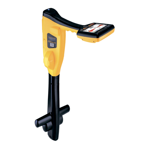
Vivax Metrotech
Vivax Metrotech vLoc3-9800 Instruction Manual
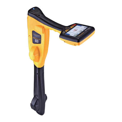
Vivax Metrotech
Vivax Metrotech vLoc3-Cam Instruction Manual
Vivax Metrotech
Vivax Metrotech vLocPro2 User manual
Vivax Metrotech
Vivax Metrotech A-frame User manual
Vivax Metrotech
Vivax Metrotech vLoc3 Series User manual
Vivax Metrotech
Vivax Metrotech VM-540 User manual
Vivax Metrotech
Vivax Metrotech vLocPro Series Reference guide
