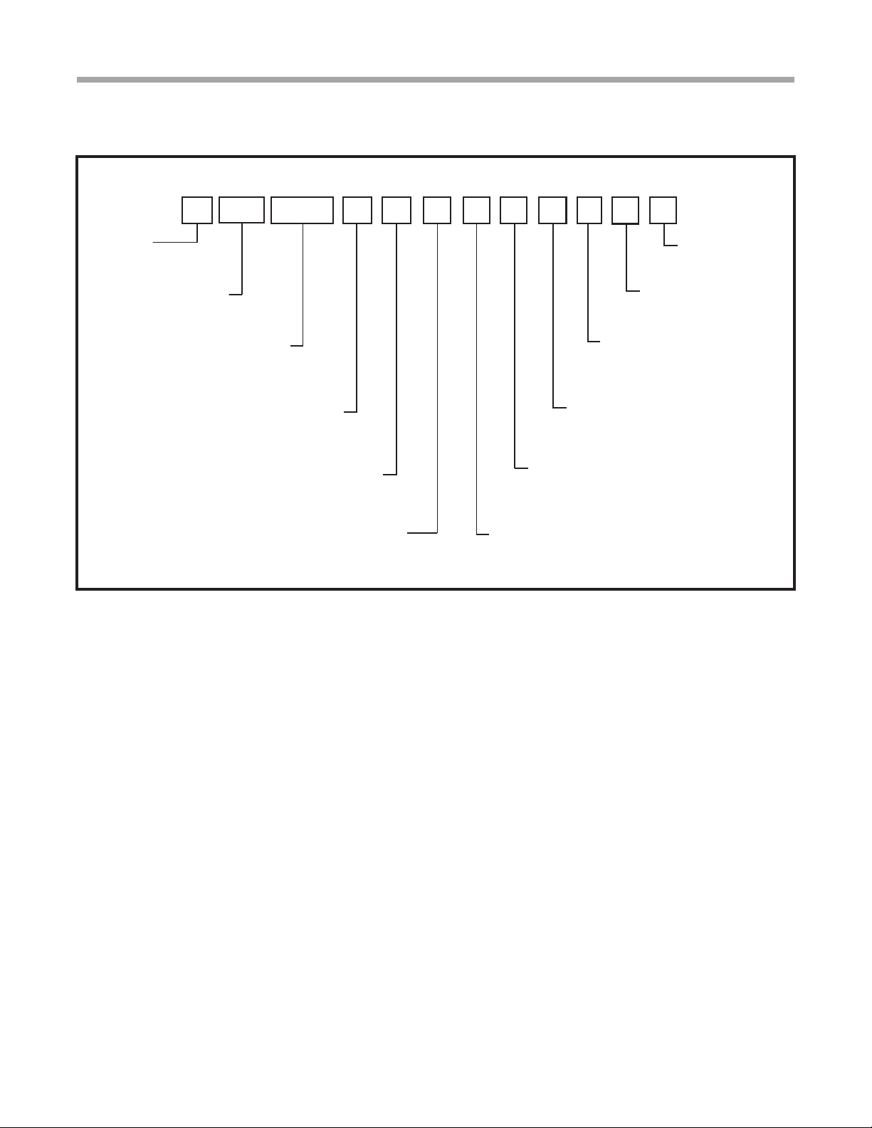
Tranquility®Fluid Cooler – 60 Hz
Rev.: February 22, 2022
climatemaster.com 5
General Information
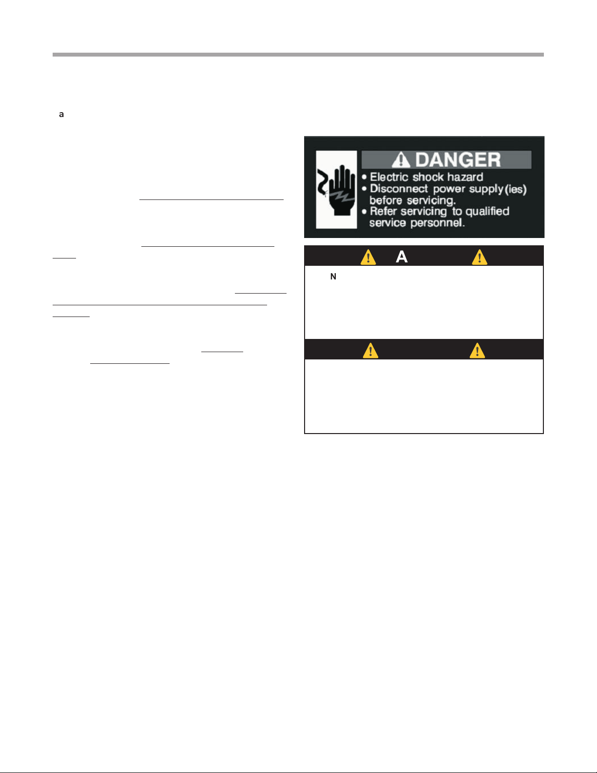
CAUTION! DO NOT store or install units in corrosive
environments or in locations subject to temperature or
humidity extremes (e.g., attics, garages, rooftops, etc.).
Corrosive conditions and high temperature or humidity can
signicantly reduce performance, reliability, and service life.
Always move and store units in an upright position. Tilting
units on their sides will cause equipment damage.
⚠
CAUTION!
⚠
⚠
CAUTION!
⚠
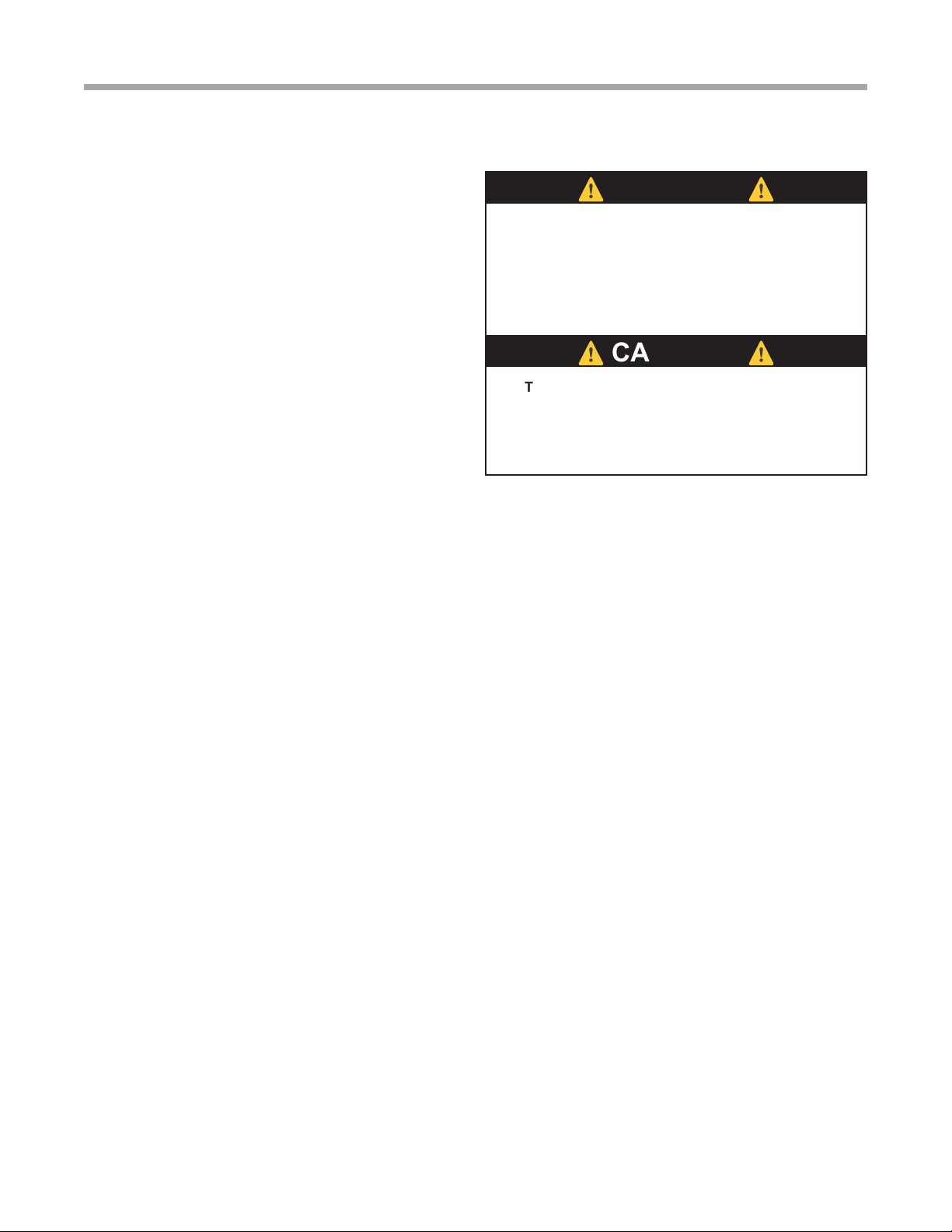
CAUTION! CUT HAZARD - Failure to follow this caution
may result in personal injury. Sheet metal parts may have
sharp edges or burrs. Use care and wear appropriate
protective clothing, safety glasses and gloves when
handling parts and servicing equipment.
Inspection
Upon receipt of the equipment, carefully check the
shipment against the bill of lading. Make sure all units
have been received. Inspect the packaging of each unit,
and inspect each unit for damage. Insure that the carrier
makes proper notation of any shortages or damage on all
copies of the freight bill and completes a common carrier
inspection report. Concealed damage not discovered
during unloading must be reported within 60 days
of receipt of shipment. To le a freight claim contact
your ClimateMaster Customer Service Representative
immediately upon discovery of damage or missing parts,
but not more than 60 days after shipment. Contact
ClimateMaster by telephone (800) 299-9747.
Storage
Equipment should be stored in its original packaging in
a clean, dry area. Store units in an upright position at all
times. Stack units a maximum of 2 units high.
Unit Protection
Cover units on the job site with either the original
packaging or an equivalent protective covering. Cap
the open ends of pipes stored on the job site. In areas
where painting, plastering, and/or spraying has not
been completed, precautions must be taken to avoid
physical damage to the units and contamination by
foreign material. Physical damage and contamination
may prevent proper start-up and may result in costly
equipment clean-up.
Examine all pipes, ttings, and valves before installing
any of the system components. Remove any dirt or
debris found in or on these components.
Pre-Installation
Installation, Operation, and Maintenance instructions
are provided with each unit. The installation site chosen
should include adequate service clearance around the
unit. Before unit start-up, read all manuals and become
familiar with the unit and its operation. Thoroughly check
the system before operation.
Prepare units for installation as follows:
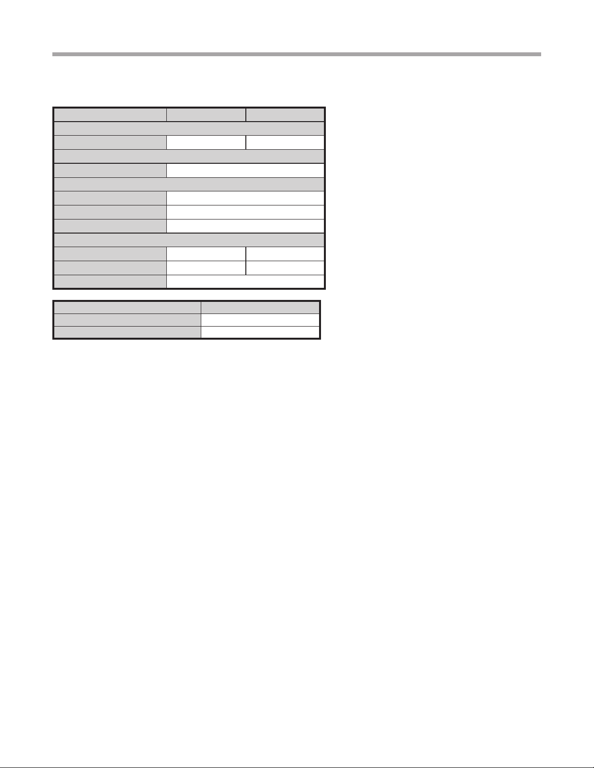
1. Compare the electrical data on the unit nameplate
with ordering and shipping information to verify that
the correct unit has been shipped.
2. Keep the cabinet covered with the original packaging
until installation is complete and all plastering,
painting, etc. is nished.
3. Verify tubing is free of kinks or dents and that it does
not touch other unit components.
4. Inspect all electrical connections. Connections must
be clean and tight at the terminals.
5. Locate and verify any accessory items that may be
packaged inside the unit.