Nibe ACK 22 User manual

MAV 0922-1
ACK 22
031263 ACK 22
MONTERINGSANVISNING KABELKIT ACK 22 TILL ESV 22 ELLER VCC 22
SE
INSTALLATION INSTRUCTIONS CABLE KIT ACK 22 FOR ESV 22 OR VCC 22
GB
MONTAGEANLEITUNG KABELSET ACK 22 FÜR ESV 22 ODER VCC 22
DE
LEK
LEK
LEK


MONTERINGSANVISNING
ACK 22
Allmänt
Detta tillbehör används för att ansluta tillbehören ESV 22
och VCC 22 till innemodulen ACVM 270 i NIBE SPLIT.
Innehåll
Kabelsats1st
Torxskruv, M5 självgängade2st
Buntband5st
Reläkort med kablage (AA7)1st
Etikett1st
Kopplingsplint 2x1-pol (X6)1st
Kopplingsplint 2x1-pol PE (X6)1st
Kopplingsplint 2x3-pol (X6)2st
Ändplatta för kopplingsplint (X6)1st
Dragavlastare (fäste, buntband)4st
Monteringsplåt1st
3ACK 22
SE

Elinkoppling ACVM 270
OBS!
All elektrisk inkoppling skall ske av behörig elektriker.
Elektrisk installation och ledningsdragning skall utföras
enligt gällande bestämmelser.
ACVM 270 ska vara spänningslös vid installation av
ACK 22.
Elscheman finns i slutet av denna monteringsanvisning.
Följande ledare för ACK 22 används i denna sats: 0101 till
0112.
1. Det medföljande reläkortet (AA7) monteras på det be-
fintliga reläkortet (AA6) med hjälp av plasttornen, se bild
nedan.
2. Kantkontaktkablaget kopplas in mellan det medföljande
reläkortet (AA7) och reläkort (AA6) enligt bild nedan.
HAHN
LEK
Reläkort, -AA6 Reläkort, -AA7
3. Det sammanhängande kablaget med flatstifthylsor och
nollnummer 0101 till 0103 monteras enligt följande:
Bruna ledare med nollnummer 0101 och 0102 till
flatstiftet AA7:37.
-
Bruna ledare med nollnummer 0102 och 0103 till
flatstiftet AA7:39.
-
Brun (ensam) ledare med nollnummer 0103 till flat-
stiftet AA7:41.
-
4. Montera kopplingsplintar, etikett och dragavlastare på
plåten. Skruva fast plåten med de två medföljande M5
självgängade torxskruvarna, se bild nedan.
M5, självgängade
torxskruvar
Elkoppling, X6
PE
Från tillbehör
Elkoppling,
X6
Plats för
AA7
AA6
PE2
ACK 224
SE

5. Tryck fast den 7-poliga kantkontakten med nollnummer
0108 till 0112 på reläkortet AA6 enligt bild nedan (OBS!
Notera spårningen i kantkontakten). Montera sedan de
lösa ändarna enligt följande:
Blå ledare med nollnummer 0108 till fjäderplint
X6:6a.
-
Bruna ledare med nollnummer 0109 och 0110 till
fjäderplint X6:3a.
-
Svart ledare med nollnummer 0111 till fjäderplint
X6:1a.
-
Grå ledare med nollnummer 0112 till fjäderplint
X6:2a.
-
510
0108
0109
0110
0111
0112
AA6
X6
Kant-
kontakt
7
8
6
3
2
1
4
5
Kantkontakt
HAHN
LEK
LEK
Spårning
6. De övriga enskilda ledarna anslutes enligt följande:
Brun ledare med nollnummer 0101 till fjäderplinten
X6:3b.
-
Gul/grön ledare med nollnummer 0107 till ledig
anslutning på jordflatstiftet –PE2 se bild och i fjäder-
plinten X6:5a.
-
Brun ledare med nollnummer 0104 till flatstiftet
AA7:38 och i fjäderplinten X6:4a.
-
Brun ledare med nollnummer 0105 till flatstiftet
–AA7:40 och i fjäderplinten –X6:7a.
-
Brun ledare med nollnummer 0106 till flatstiftet
–AA7:42 och i fjäderplinten –X6:8a.
-
5ACK 22
SE

INSTALLATION INSTRUCTIONS
ACK 22
General
This accessory is used to connect accessories ESV 22 and
VCC 22 to the indoor module ACVM 270 in NIBE SPLIT.
Contents
Cable set1x
Torx screw, M5 self-tapping2x
Cable ties5x
Relay card with wiring (AA7)1x
Label1x
Terminal block 2x1-pole (X6)1x
Terminal block 2x1-pole PE (X6)1x
Terminal block 2x3-pole (X6)2x
End plate for terminal block (X6)1x
Strain relief (mounting, cable tie)4x
Installation plate1x
ACK 226
GB

Electrical connection ACVM 270
NOTE
All electrical connections must be carried out by an
authorised electrician.
Electrical installation and wiring must be carried out
in accordance with the stipulations in force.
ACVM 270 must not be powered when installing ACK
22.
The electrical circuit diagram is at the end of these installation
instructions.
Following cables for ACK 22 are used in this kit: 0101 to
0112.
1. The supplied relay card (AA7) is installed on the existing
relay card (AA6) using the plastic turrets, see image be-
low.
2. Connect the edge connector wiring between the sup-
plied relay card (AA7) and relay card (AA6) as illustrated
below.
HAHN
LEK
Relay card, -AA6 Relay card, -AA7
3. The corresponding wiring with flat pin sleeves and zero
numbers 0101 to 0103 are installed as follows:
Brown cables with zero number 0101 and 0102 to
flat pin AA7:37.
-
Brown cables with zero number 0102 and 0103 to
flat pin AA7:39.
-
Brown (single) cable with zero number 0103 to flat
pin AA7:41.
-
4. Mount the terminal blocks, label and strain relief on the
mounting plate. Screw the plate into place with two
accompanying M5 self-tapping torx screws, see image
below.
M5, self-tapping torx
screws
Electrical connection, X6
PE
From accessories
Electrical
c
onnection,
X6
Space for
AA7
AA6
PE2
7ACK 22
GB

5. Press the 7-pole edge connector with zero number 0108
to 0112 on the relay card AA6 according to the image
below (NOTE! Be careful to match up the guide pin in
the edge connector with its hole in the card edge). Then
connect the loose wire ends as follows:
Blue cable with zero number 0108 to spring terminal
X6:6a.
-
Brown cables with zero number 0109 and 0110 to
spring terminal X6:3a.
-
Black cable with zero number 0111 to spring termi-
nal X6:1a.
-
Grey cable with zero number 0112 to spring terminal
X6:2a.
-
510
0108
0109
0110
0111
0112
AA6
X6
Kant-
kontakt
7
8
6
3
2
1
4
5
Edge
connector
HAHN
LEK
LEK
Guide pin
6. Connect the other individual wires as follows:
Brown cable with zero number 0101 to spring ter-
minal X6:3b.
-
Yellow/green cable with zero number 0107 to spare
connection on ground flat pin –PE2 see image and
in spring terminal X6:5a.
-
Brown cable with zero number 0104 to flat pin
AA7:38 and in spring terminal X6:4a.
-
Brown cable with zero number 0105 to flat pin
–AA7:40 and in spring terminal –X6:7a.
-
Brown cable with zero number 0106 to flat pin
–AA7:42 and in spring terminal –X6:8a.
-
ACK 228
GB

MONTAGEANLEITUNG
ACK 22
Allgemeines
Dieser Artikel wird verwendet, um Zubehör ESV 22 und VCC
22 mit dem Innenmodul ACVM 270 in NIBE SPLIT zu verbin-
den.
Inhalt
Kabelsatz1 St.
Torxschraube, M5 selbstschneidend2 St.
Kabelbinder5 St.
Relaiskarte mit Kabeln (AA7)1 St.
Etikett1 St.
Anschlussklemme 2x1-pol. (X6)1 St.
Anschlussklemme 2x1-pol. PE (X6)1 St.
Anschlussklemme 2x3-pol. (X6)2 St.
Endplatte für Anschlussklemme (X6)1 St.
Zugentlastung (Befestigungsband, Kabelbinder)4 St.
Montageblech1 St.
9ACK 22
DE

Elektrischer Anschluss ACVM 270
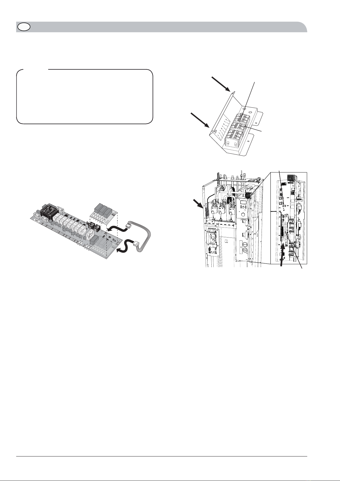
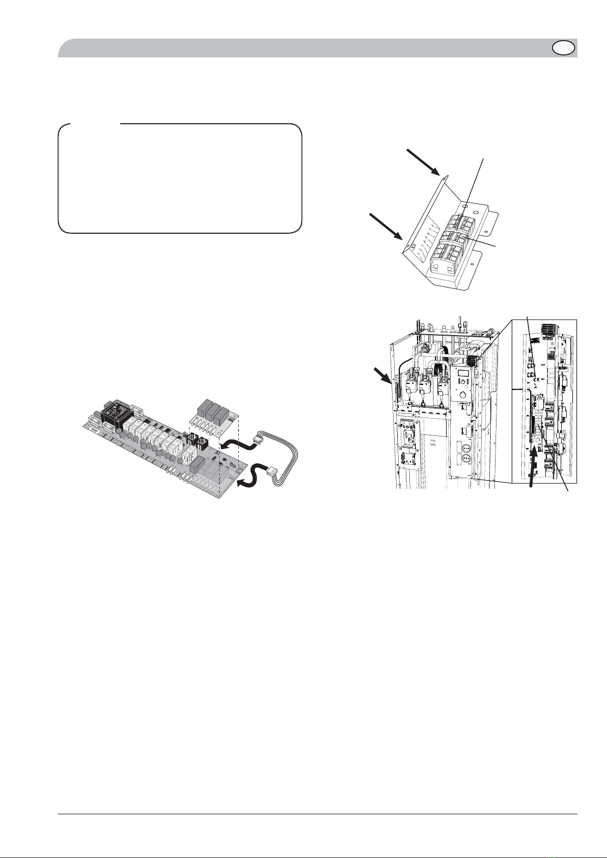
HINWEIS!
Alle elektrischen Anschlüsse müssen von einem befug-
ten Elektriker ausgeführt werden.
Bei der Elektroinstallation und beim Verlegen der Lei-
tungen sind die geltenden Vorschriften zu berücksich-
tigen.
ACVM 270 darf bei der Installation von ACK 22 nicht
mit Spannung versorgt werden.
Der Schaltplan befindet sich am Ende dieser Montageanlei-
tung.
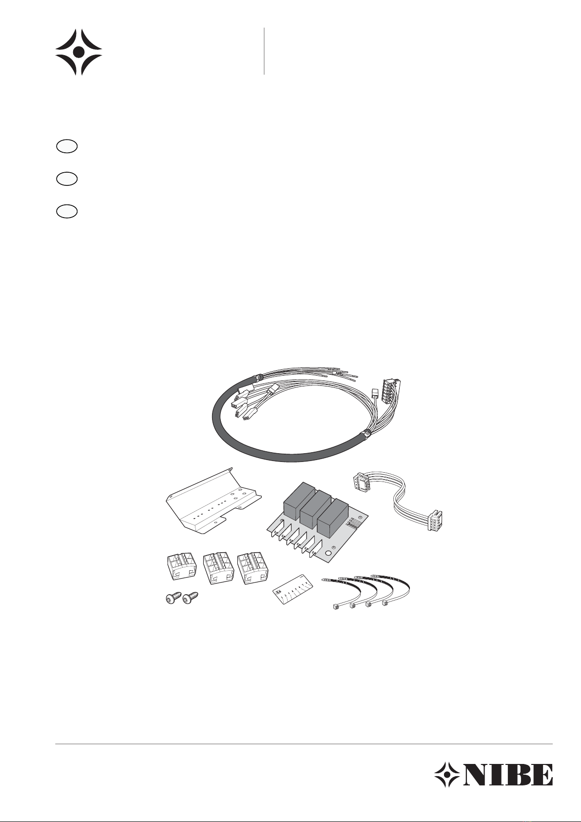
Dieser Satz enthält folgende Leiter für ACK 22: 0101 bis
0112.
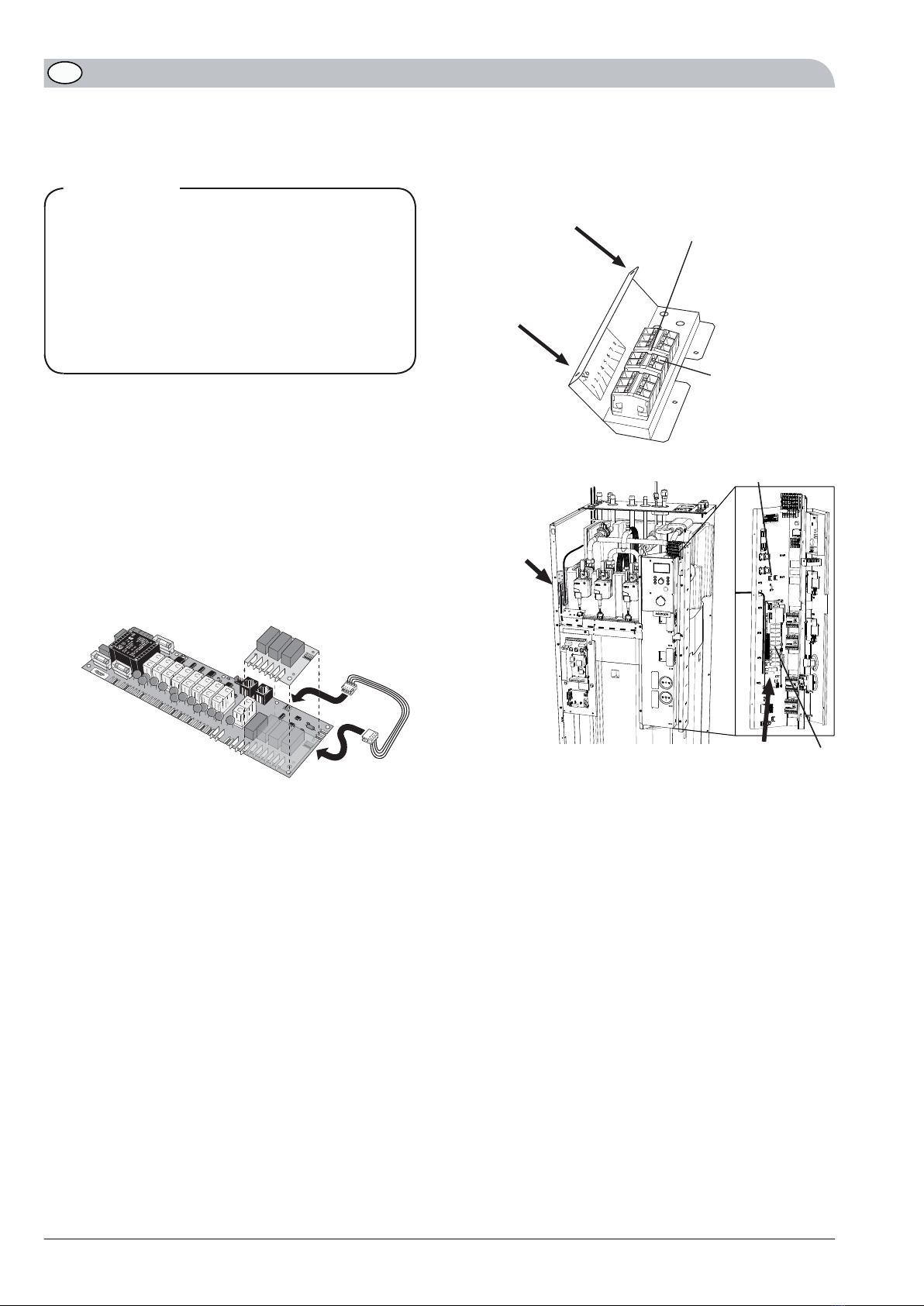
1. Die beiliegende Relaiskarte (AA7) wird mithilfe des
Kunststoffdorns an der vorhandenen Relaiskarte (AA6)
montiert (siehe Abbildung unten).
2. Die Kabel für den Eckkantenstecker werden mit der
beiliegenden Relaiskarte (AA7) und der Relaiskarte (AA6)
verbunden (siehe Abbildung unten).
HAHN
LEK
Relaiskarte, -AA6 Relaiskarte, -AA7
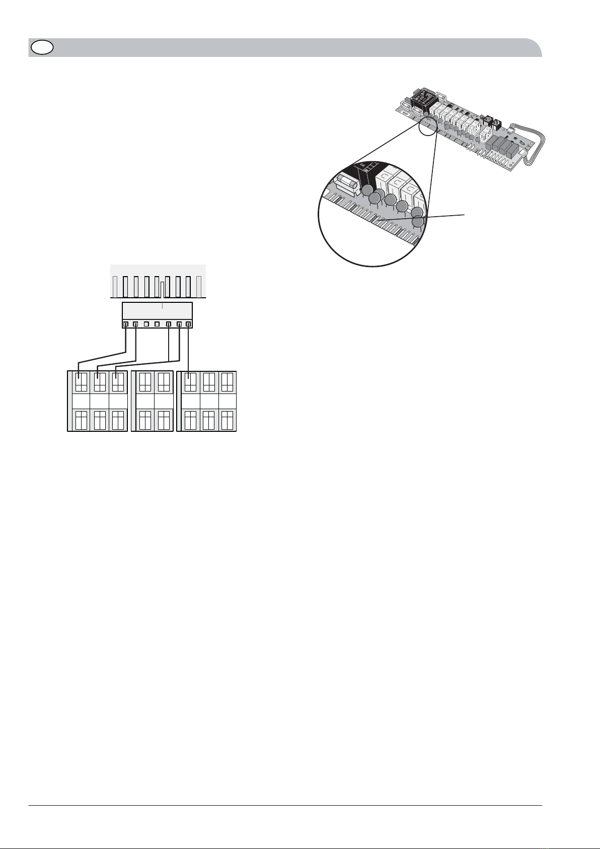
3. Die zusammenhängenden Kabel mit Flachstifthülsen und
den Nummern 0101 sowie 0103 werden wie folgt
montiert:
Braune Leiter mit Nummer 0101 und 0102 an
Flachstift AA7:37.
-
Braune Leiter mit Nummer 0102 und 0103 an
Flachstift AA7:39.
-
Brauner Leiter (einzeln) mit Nummer 0103 an
Flachstift AA7:41.
-
4. Befestigen Sie Anschlussklemmen, Etikett und Zugentlas-
tung am Blech. Verschrauben Sie das Blech mithilfe der
zwei selbstschneidenden M5-Torxschrauben im Lieferum-
fang (siehe Abbildung unten).
M5, selbstschneidende
Torxschrauben
Elektrischer Anschluss, X6
PE
Von Zubehör
E
lektrischer
Anschluss,
X6
Platz für
AA7
AA6
PE2
ACK 2210
DE

5. Drücken Sie den 7-poligen Eckkantenstecker mit Nummer
0108 bis 0112 auf die Relaiskarte AA6 (siehe Abbildung
rechts). Beachten Sie die Nut im Eckkantenstecker.)
Bringen Sie danach die losen Enden wie folgt an:
Blauer Leiter mit Nummer 0108 an Federklemme
X6:6a.
-
Blauer Leiter mit Nummer 0109 und 0110 an Fe-
derklemme X6:3a.
-
Schwarzer Leiter mit Nummer 0111 an Federklemme
X6:1a.
-
Grauer Leiter mit Nummer 0112 an Federklemme
X6:2a.
-
510
0108
0109
0110
0111
0112
AA6
X6
Kant-
kontakt
7
8
6
3
2
1
4
5
Eckkantenstecker
HAHN
LEK
LEK
Nut
6. Die restlichen einzelnen Leiter werden wie folgt ange-
schlossen:
Brauner Leiter mit Nummer 0101 an Federklemme
X6:3b.
-
Gelber/grüner Leiter mit Nummer 0107 am freien
Anschluss am Erdungsflachstift –PE2 (siehe Abbil-
dung) und an Federklemme X6:5a.
-
Brauner Leiter mit Nummer 0104 an Flachstift
AA7:38 und Federklemme X6:4a.
-
Brauner Leiter mit Nummer 0105 an Flachstift
–AA7:40 und Federklemme –X6:7a.
-
Brauner Leiter mit Nummer 0106 an Flachstift
–AA7:42 und Federklemme –X6:8a.
-
11ACK 22
DE

Elschema/Wiring diagram/Elektrischer schaltplan
ACK 22
ACK 2212

13ACK 22

ACK 2214


PL
NO
NL
FI
DK
DE
CZ
NIBE – Haato OY, Valimotie 27, 01510 Vantaa
3C Broom Business Park, Bridge Way, Chesterfield S41 9QG
NIBE-BIAWAR Sp. z o. o. Aleja Jana Pawła II 57, 15-703 BIAŁYSTOK
Tel: 085 662 84 90 Fax: 085 662 84 14 E-mail: sekretariat@biawar.com.pl www.biawar.com.pl
NIBE AB, Fekjan 15F, 1394 Nesbru
NIBE Energietechniek B.V., Postbus 2, NL-4797 ZG WILLEMSTAD (NB)
Vølund Varmeteknik, Filial af NIBE AB, Brogårdsvej 7, 6920 Videbæk
NIBE Systemtechnik GmbH, Am Reiherpfahl 3, 29223 Celle
Druzstevni zavody Drazice s.r.o, Drazice 69, CZ - 294 71 Benatky nad Jizerou
CH NIBE Wärmetechnik AG, Winterthurerstrasse 710, CH-8247 Flurlingen
AT KNV Energietechnik GmbH, Gahberggasse 11, 4861 Schörfling
NIBE AB Sweden, Box 14, Järnvägsgatan 40, SE-285 21 Markaryd
GB NIBE Energy Systems Ltd,
Table of contents
Languages:
Other Nibe Cables And Connectors manuals