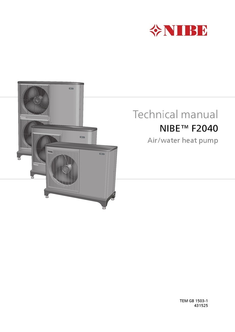
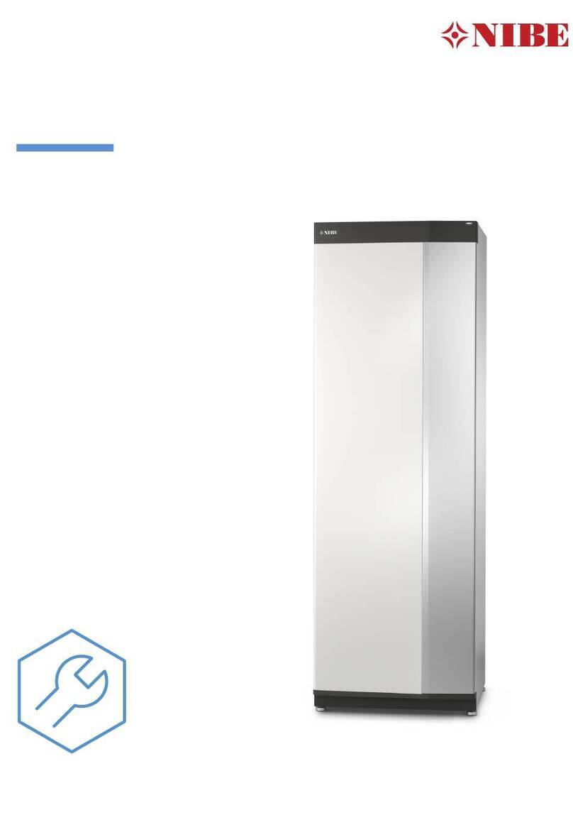
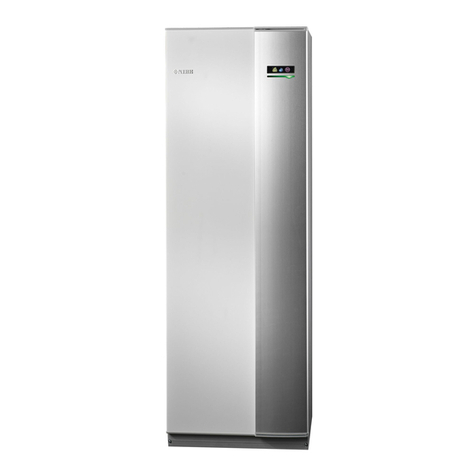
Nibe VVM 500 User manual

Service manual
APH
NIBE™ VVM 500
Indoor module
SEM GB 1514-2
M11495


Table of Contents
21 Important information
2Document information
2Safety information
52 Indoor module's design
5VVM 500
6Pipe connections
6HVAC components
6Sensors etc.
6Electrical components
6Miscellaneous
73 System description
7Principle of operation
8System diagram
94 Current circuit
9Load monitor
105 Component description
10Components
12Sensors
13Electronics
156 Troubleshooting
15Alarm list
23Troubleshooting guide
28Function check, components
307 Component replacement
30Basic
34Main components
45Circuit board and electronics
488 Technical data
48Dimensions and setting-out coordinates
49Technical specifications
51Hot water capacity
52Index
1Table of Contents |NIBE™ VVM 500

Document information
This technical manual is a complement to the Installer
handbook for VVM 500, containing:
■Component description.
■Information to facilitate fault-tracing.
■Instructions for replacing components.
■Wiring diagram.
■Supplementary technical information.
The document applies to VVM 500 with software ver-
sions up to and including v4272R5.
The heat pump software version can be found in the
info menu (menu 3.1).
Safety information
This manual describes installation and service proced-
ures for implementation by specialists.
This appliance can be used by children
aged from 8 years and above and per-
sons with reduced physical, sensory or
mental capabilities or lack of experience
and knowledge if they have been given
supervision or instruction concerning
use of the appliance in a safe way and
understand the hazards involved. Chil-
dren shall not play with the appliance.
Cleaning and user maintenance shall
not be made by children without super-
vision.
Rights to make any design or technical
modifications are reserved.
©NIBE 2015.
Symbols
NOTE
This symbol indicates danger to machine or
person.
Caution
This symbol indicates important information
about what you should observe when main-
taining your installation.
TIP
This symbol indicates tips on how to facilitate
using the product.
Marking
The CE marking means that NIBE ensures that the
product meets all regulations that are placed on it
based on relevant EU directives. The CE mark is obligat-
ory for most products sold in the EU, regardless where
they are made.
NIBE™ VVM 500Chapter 1 | Important information2
1 Important information

Serial number
The serial number can be found at the bottom right of
the front cover and in the info menu (menu 3.1).
Serial number
Caution
Always give the product's serial number (14
digits) when reporting a fault.
3Chapter 1 | Important informationNIBE™ VVM 500

Contact information
KNV Energietechnik GmbH, Gahberggasse 11, 4861 SchörflingAT
Tel: +43 (0)7662 8963-0 Fax: +43 (0)7662 8963-44 E-mail: mail@knv.at www.knv.at
NIBE Wärmetechnik AG, Winterthurerstrasse 710, CH-8247 FlurlingenCH
Druzstevni zavody Drazice s.r.o, Drazice 69, CZ - 294 71 Benatky nad JizerouCZ
NIBE Systemtechnik GmbH, Am Reiherpfahl 3, 29223 CelleDE
Vølund Varmeteknik A/S, Member of the Nibe Group, Brogårdsvej 7, 6920 VidebækDK
NIBE Energy Systems OY, Juurakkotie 3, 01510 VantaaFI
NIBE Energy Systems France Sarl, Zone industrielle RD 28, Rue du Pou du Ciel, 01600 ReyrieuxFR
NIBE Energy Systems Ltd, 3C Broom Business Park, Bridge Way, Chesterfield S41 9QGGB
NIBE Energietechniek B.V., Postbus 634, NL 4900 AP OosterhoutNL
ABK AS, Brobekkveien 80, 0582 Oslo, Postadresse: Postboks 64 Vollebekk, 0516 OsloNO
NIBE-BIAWAR Sp. z o. o. Aleja Jana Pawła II 57, 15-703 BIAŁYSTOKPL
Tel: 085 662 84 90 Fax: 085 662 84 14 E-mail: sekretariat@biawar.com.pl www.biawar.com.pl
© "EVAN" 17, per. Boynovskiy, Nizhny NovgorodRU
NIBE AB Sweden, Box 14, Hannabadsvägen 5, SE-285 21 MarkarydSE
For countries not mention in this list, please contact Nibe Sweden or check www.nibe.eu for more information.
NIBE™ VVM 500Chapter 1 | Important information4

VVM 500
APH
VVM 500
XL2
AA3
QM1
AA1
EB1
FD1
FA1
XL9
QN35
PF3PF1
XL3
GP12
QN10
AA2
SF1
UB1
AA4-XJ4
AA4
AA4-XJ3
GP1
QM20
BT63
BT2
UB2
XL8
XL8
XL9
XL4
CM1
XL2
XL3
XL14
XL13XL19
XL18XL1
QN11
XL1
BT6
BT54
QM20
BT7
PF3
PF1
XL39
XL39
XL18
XL14
XL19
XL13
AA7
W130
BT3
5Chapter 2 | Indoor module's designNIBE™ VVM 500
2 Indoor module's design

Pipe connections
Connection, heating medium flow lineXL1
Connection, heating medium return lineXL2
Connection, cold waterXL3
Connection, hot waterXL4
Connection, docking in heating mediumXL8
Connection, docking out heating mediumXL9
Connection, solar system flow lineXL13
Connection, solar system return lineXL14
Connection, docking in high tempXL18
Connection, docking out high tempXL19
Connection, docking poolXL39
HVAC components
Expansion tank (connection)CM1
Circulation pumpGP1
Charge pumpGP12
Drain valve, water heaterQM1
Venting, climate systemQM20
Shuttle valve, climate system/water heater, flow
line
QN10
Shunt valveQN11
Shuttle valve, climate system/water heater, re-
turn line
QN35
Sensors etc.
Temperature sensors, heating medium flowBT2
Temperature sensors, heating medium returnBT3
Temperature sensor, hot water, controlBT6
Temperature sensor, hot water, displayBT7
Temperature sensor, solar coilBT54
Temperature sensor, heating medium supply
after immersion heater
BT63
Electrical components
Immersion heater cardAA 1
Base cardAA 2
Input circuit boardAA 3
Display unitAA 4
AA4-XJ3 USB socket
AA4-XJ4 Service socket
Extra relay circuit boardAA 7
Immersion heaterEB 1
Miniature circuit-breakerFA 1
Temperature limiterFD 1
SwitchSF 1
Miscellaneous
Rating platePF 1
Serial number platePF 3
Cable glandUB1
Cable glandUB2
Designations in component locations according to
standard IEC 81346-1 and 81346-2.
NIBE™ VVM 500Chapter 2 | Indoor module's design6

Principle of operation
XL8 XL9 CM1 XL3 XL2
XL1XL4BT7XL39
BT2
GP1
BT3
GP12
QN10
QN35
QN11
BT6
BT54
XL2
XL9
QN35
XL3
GP12
QN10
BT3
GP1
BT2
XL8
XL4
CM1
QN11
XL1
BT6
BT54
BT7
XL39
List of components
Pipe connections
Connection, heating medium flow lineXL1
Connection, heating medium return lineXL2
Connection, cold waterXL3
Connection, hot waterXL4
Connection, docking in heating mediumXL8
Connection, docking out heating mediumXL9
Connection, docking poolXL39
HVAC components
Expansion tank (connection)CM1
Circulation pumpGP1
Charge pumpGP12
Shuttle valve, climate system/water heater, flow
line
QN10
Shunt valveQN11
Shuttle valve, climate system/water heater, re-
turn line
QN35
Sensors
Temperature sensors, heating medium flowBT2
Temperature sensors, heating medium returnBT3
Temperature sensor, hot water, controlBT6
Temperature sensor, hot water, displayBT7
Temperature sensor, solar coilBT54
7Chapter 3 | System descriptionNIBE™ VVM 500
3 System description

System diagram
-FL2
-CM1
-EB15
-EP30
-EP30-BT53
-EP8
-AA25
-CM5
-GP4
-QM45
-RM3
-QM43
-QM44
T P
-FL4
-RM4 T
-GP30
-FL1
-QM40-RM1
-GP20
-BT3
-BT2
-QN25
-EP21
-AA25
-GP9
-BT52
-EM1
-AA25
-EM1
-GP15
-EB101
-GP9 -BT51 -HQ4
-EP5
-AA25
-CL11
-CL11-QN19
Climate systemEP 21Accessory cardAA 5
Solar kit SCA 30EP 30Control unitAA 25
Safety valve, climate systemFL 2Temperature sensors, heating medium flowBT 2
Safety valve, solarFL 4Temperature sensors, heating medium returnBT 3
Circulation pump, solarGP 4Temperature sensor, poolBT 51
Circulation pump, poolGP 9Temperature sensor, boilerBT 52
Circulation pump, external heat sourceGP 15Temperature sensor, solar panelBT 53
Circulation pumpGP 20Pool kit POOL 500CL 11
Pump station SPS 10, SPS 20GP 30Expansion vessel, heating mediumCM 1
Particle filterHQ 4Expansion vessel, solarCM 5
Shut-off valveQM 4XVVM 500EB 15
Shunt valveQN 11F20XX/F2300EB 100
Three way valve, poolQN 19Oil, gas, or electric boilerEM 1
Non-return valveRM XExchanger, poolEP 5
Solar panelEP 8
NIBE™ VVM 500Chapter 3 | System description8

Load monitor
The current sensors are connected to AA3-X4:1-4.
Function:
■If any of the internal phases exceed the set value and
the phase sequence is not detected, electrical power
is disconnected from one of the internal phases. Be-
cause the phase sequence is not detected this can
mean that the incorrect phase sequence is disconnec-
ted, so that the output is still too high. The heat pump
continues by disconnecting another phase, until the
current does not exceed the set value. If the current
still exceeds the set value when all internal phases
are disconnected, the same process is performed for
external additional heat, if applicable and is set to
step-controlled additional heat.
NOTE
Do not disconnect the external additional
heat if it is set to give additional heat in one
step.
.
■If the phase sequence is detected the electrical out-
put is disconnected in the phase that exceeds the set
value. This will also handle any external additional
heat.
■If disconnecting the phases does not work, the heat
pump will finally disengage.
■Reconnection occurs when the current has fallen to
a value low enough to permit reconnection.
NOTE
VVM 500 must be filled with water before the
phase sequence is detected.
For the heat pump to disconnect the electrical output
in the correct phase, the phase sequence must have
been detected during the installation. In the menu
5.1.12 the phase sequence must be detected after-
wards. An unsuccessful detection may be due to the
current sensors not being correctly connected or that
other electrical equipment started or stopped during
detection.
Factory settingNameMenu
16Afuse size5.1.12
detect phase order
9Chapter 4 | Current circuitNIBE™ VVM 500
4 Current circuit

Components
DescriptionComponent
Between brown cable and blue cable 26.38 ohmImmersion heater
(EB1) Between the white cables 53.20 ohm
390 ±2
28 ±1337 ±2
142,7
(114)
146
687 ±5
(325)
(637)
(63)
(85)
(135)
50R ±5
63,5
Ø
(512)
Brun kabel
Blå kabel
Vit kabel
Actuator motor: 7 VA, 230/24 VAC, 50 Hz, IP 40. Running time approx 8 sec.Reversing valve
(QN10, QN35) Max. operating pressure: 1.0 MPa
Operating temperature: 5 - 80 °C (90 °C briefly)
56 56 Ø28
30
54
106
142
Ø28
NIBE™ VVM 500Chapter 5 | Component description10
5 Component description

DescriptionComponent
E6PWM7-15/130G NIBE STRONGHeating medium
pump (GP1) Control signal: PWM 0-10 V DC (max-min speed)
and
140,2 ± 3
112,2 ± 2
130
ISO 228/1-G1
Charge pump (GP12)
GP1 to 2014-04
Cable, black:
H03V2V2-F 3G 0,5mm²
Cable, black:
LIYWYW 2x0,35mm²
250 ± 15
(from grommet).
300 ± 20
(from grommet).
4
4
3
2
1
6
6
6
Ø86,7
140,2±3
112,2±2
GP1 from and including 2014-04
141 ±2
107 ±1
130±0,5
71 ±0,5
116±0,5
(43,5)
(84)
G 1"
Flowdirection
1.
11Chapter 5 | Component descriptionNIBE™ VVM 500

Sensors
Data temperature sensor
Voltage (VDC)Resistance (kOhm)Temperature (°C)
3.256351.0-40
3.240251.6-35
3.218182.5-30
3.189133.8-25
3.15099.22-20
3.10574.32-15
3.04756.20-10
2.97642.89-5
2.88933.020
2.78925.615
2.67320.0210
2.54115.7715
2.39912.5120
2.24510.0025
2.0838.04530
1.9166.51435
1.7525.30640
1.5874.34845
1.4263.58350
1.2782.96855
1.1362.46760
1.0072.06865
0.8911.73970
0.7851.46975
0.6911.24680
0.6071.06185
0.5330.90890
0.4690.77995
0.4140.672100
0.2500.380120
0.1200.180150
NIBE™ VVM 500Chapter 5 | Component description12

Electronics
Immersion heater card (AA1)
IndicationLED
A steady light means that the relevant
relay is engaged.
K1 - K9: Or-
ange
FunctionOutput
Supply L1K1
Supply L2K2
Supply L3K3
Immersion heater EB1 2 kWK4
Not usedK5
Immersion heater EB1 2 kWK6
Immersion heater EB1 only at 3 kWK7
Immersion heater EB1 2 kWK8
Immersion heater EB1 1 kW or 3 kWK9
Base card (AA2)
IndicationLED
A steady light means that 12 V is OK.Power:
Green
Flashing once/sec. Indicates that the
processor is OK.
Run: Green
Flashes irregularly during communication.Com: Green
Continuous light during active output.PWM1: Or-
ange
Continuous light during active output.PWM2: Or-
ange
A steady light means that the relevant
relay is engaged.
K1 - K4: Or-
ange
Outputs
FunctionOutput
Control signal HM pump (GP1)PWM1
Control signal charge pump (GP12)PWM2
Reversing valve (QN10).K1
Charge pump (GP12).K2
Circ-pump (GP1).K3
FunctionOutput
No function.K4
Input circuit board (AA3)
FunctionInputs
Current sensor input (GND).X4-1
Current sensor input (BE1).X4-2
Current sensor input (BE2).X4-3
Current sensor input (BE3).X4-4
Outdoor sensor input (BT1).X6:1- 2
Room sensor input (BT50).X6:3-4
AUX1X6:9-10
AUX2X6:11-12
AUX3X6:13-14
AUX4X6:15-16
AUX5X6:17-18
FunctionOutput
Potential free relay CommonK1X7:1
Potential free relay NOK1X7:2
Potential free relay NCK1X7:3
Display unit (AA4)
The display unit consists of:
■a colour screen where all information is displayed.
■a status lamp.
■navigation buttons (OK button, Back button and
Control knob).
■a USB socket.
■a service socket.
FunctionStatus lamp
Normal functionLights green
Emergency mode activatedLights yellow
Alarm trippedLights red
13Chapter 5 | Component descriptionNIBE™ VVM 500

Extra relay circuit board (AA7)
IndicationLED
A steady light means that the relevant
relay is engaged.
K1 - K3: Or-
ange
FunctionOutput
Shunt valve close (QN11)K1
Shunt valve open (QN11)K2
Reversing valve (QN35)K3
NIBE™ VVM 500Chapter 5 | Component description14

Alarm list
A-alarm
In event of an A alarm the red lamp on the front lights and an alarm icon is displayed. First go through the suggested
actions shown in the display.
May be due toHeat pump action.CauseAlarm text on
the display
Alarm
no.
See fault-tracing schedule page
23.
Calculated flow temperature is
set to min supply line (menu
1.9.3).
Sensor not connected/defect-
ive
(outdoor sensor)
Sensor fault BT11
See fault-tracing schedule page
24.
Uses BT3 if available.
If BT3 is not available, BT63 is
used.
Sensor not connected/defect-
ive
(heating medium supply)
Sensor fault BT22
See fault-tracing schedule page
24.
No actionSensor not connected/defect-
ive
Sensor fault BT33
(heating medium return)
See fault-tracing schedule page
24.
Uses BT54Sensor not connected/defect-
ive
Sensor fault BT66
(hot water, controlling)
See fault-tracing schedule page
23.
Automatic reset.Sensor not connected/defect-
ive
Sensor fault
BT25
25
(heating medium flow, extern-
al)
See fault-tracing schedule page
24.
Blocks internal electrical addi-
tion.
Sensor not connected/defect-
ive
Sensor fault
BT63
31
See fault-tracing schedule page
25.
Switches off solar function.Sensor not connected/defect-
ive
Sensor fault
EP30 - BT53
33
(solar panel)
See fault-tracing schedule page
25.
Switches off solar function.Sensor not connected/defect-
ive
Sensor fault
EP30 - BT54
34
(solar coil)
See fault-tracing schedule page
25.
Shunt closes. Burner stops.Sensor not connected/defect-
ive
Sensor fault
EM1 - BT52
35
(boiler)
See fault-tracing schedule page
25.
Controls the return sensor
(EP21-BT3)
Sensor not connected/defect-
ive
Sensor fault
EP21 - BT2
36
(supply temperature sensor,
extra climate system 1)
See fault-tracing schedule page
25.
Controls the return sensor
(EP22-BT3)
Sensor not connected/defect-
ive
Sensor fault
EP22 - BT2
37
(supply temperature sensor,
extra climate system 2)
15Chapter 6 | TroubleshootingNIBE™ VVM 500
6 Troubleshooting

May be due toHeat pump action.CauseAlarm text on
the display
Alarm
no.
See fault-tracing schedule page
25.
Controls the return sensor
(EP23-BT3)
Sensor not connected/defect-
ive
Sensor fault
EP23- BT2
38
(supply temperature sensor,
extra climate system 3)
See fault-tracing schedule page
25.
Shuts off cooling, Closes shunt
(QN18) for cooling.
Sensor BT64 not connected,
defective.
Sensor fault
EQ1–BT64
39
Motor protection on one
phase (Norway) machine has
probably blown.
45
Internal electrical addition is
blocked.
Temperature limiter has
tripped
The temperat-
ure limiter has
tripped
52
Check serial numberThe compressor stops, all relay
outputs are set to 0 V
Serial number and program
do not match
Incorrect pro-
gram
56
Compressor blocked.Serial number and program
do not match each other.
Incorrect pro-
gram
57
All relay outputs are set to 0 V.
See fault-tracing schedule on
page 26.
Blocking the relevant com-
pressor. Calculated flow temper-
ature is set to min supply line.
Communication with the in-
put card missing for 60 secs.
Communication
fault with PCA
input EB15
70
See fault-tracing schedule on
page 27.
Compressor (EB101) blocked.Communication with the base
card missing for 15 secs.
Communication
fault with PCA
base-AA2
71
- Check communication cablesAccessory is blocked.Communication with the ac-
cessory card missing for 15
secs.
Existing commu-
nication fault
with ”access-
ory".
73 -
95 - Check the setting of the
dipswitch.
- Check communication cablesAccessory is blocked.Communication with room
unit zone 1-4 missing for 60
secs.
Existing commu-
nication fault
with ”room
unit".
96 -
99
Check fuses, voltages to the
accessory card .
Accessory blocked.Temporary communication
fault HW comfort.
Com. error Acc -
QZ1
206
Check that the communication
cables are correctly connected.
Check the setting of the
dipswitch.
- Check the communication
cables.
Switches off step controlled
additional heat.
Communication with the ac-
cessory card missing for 15
secs.
Communication
fault ACC EB1.
208
- Check settings on the
dipswitch.
See relevant manual.Compressor blocked.See relevant manual.High pressure
alarm.
220
NIBE™ VVM 500Chapter 6 | Troubleshooting16

May be due toHeat pump action.CauseAlarm text on
the display
Alarm
no.
See relevant manual.Compressor blocked.See relevant manual.Low pressure
alarm.
221
See relevant manual.Compressor blocked.See relevant manual.Motor protec-
tion alarm.
222
See relevant manual.Compressor blocked.See relevant manual.Sensor fault.223
See relevant manual.Compressor blocked.See relevant manual.Fan alarm.224
See relevant manual.Compressor blocked.See relevant manual.Supply/return
line.
225
See relevant manual.Compressor blocked.See relevant manual.Sensor fault.227
See relevant manual.Compressor blocked.See relevant manual.Defrosting fault.228
See relevant manual.Compressor blocked.See relevant manual.Short operating
time.
229
See relevant manual.Compressor blocked.See relevant manual.Hot gas alarm.230
See relevant manual.Compressor blocked.See relevant manual.Phase sequence
fault.
231
See relevant manual.Compressor blocked.See relevant manual.Low evapora-
tion.
232
See IHB SMS40 for fault tracing.Accessory is blocked.Communication with the ac-
cessory card missing for 15
secs.
Communication
fault ACC
SMS40.
250
See IHB Modbus40 for fault
tracing.
Accessory is blocked.Communication with the ac-
cessory card missing for 15
secs.
Communication
fault ACC Mod-
bus40.
251
Faulty communication cableCompressor blocked.Communication with heat
pump missing.
Slave heat pump
1 comm fault.
252
See relevant manual.Compressor blocked.High VVX temp (E35)This alarm is
generated by
the heat pump
261
See relevant manual.Compressor blocked.Inverter fault, high temperat-
ure.
This alarm is
generated by
the heat pump
262
See relevant manual.Compressor blocked.Inverter error, high current
(E47)
This alarm is
generated by
the heat pump
263
See relevant manual.Compressor blocked.inverter error, com (E45)This alarm is
generated by
the heat pump
264
See relevant manual.Compressor blocked.inverter fault, pcb (E46)This alarm is
generated by
the heat pump
265
17Chapter 6 | TroubleshootingNIBE™ VVM 500

May be due toHeat pump action.CauseAlarm text on
the display
Alarm
no.
See relevant manual.Compressor blocked.Low refrigerant amount (E57)This alarm is
generated by
the heat pump
266
See relevant manual.Compressor blocked.Inverter error, start error (E59)This alarm is
generated by
the heat pump
267
See relevant manual.Compressor blocked.Inverter fault, convThis alarm is
generated by
the heat pump
268
See relevant manual.Compressor blocked.Sensor fault MHI exchange,
(E37)
This alarm is
generated by
the heat pump
277
See relevant manual.Compressor blocked.Sensor fault MHI ambient air,
(E38)
This alarm is
generated by
the heat pump
278
See relevant manual.Compressor blocked.Sensor fault MHI discharge,
(E39)
This alarm is
generated by
the heat pump
279
See relevant manual.Compressor blocked.Sensor fault MHI suction,
(E53)
This alarm is
generated by
the heat pump
280
See relevant manual.Compressor blocked.Sensor fault MHI LP, (E54)This alarm is
generated by
the heat pump
281
Check communication cablesAccessory is blocked.Temporary Comm. Fault Act-
ive 4-pipe cooling ULVP
Com. error Acc.
–EQ1
283
Check settings of the dipswitch
Check communication cables.Master blocks relevant com-
pressor. The compressors are
stopped on the slave.
Communication with the slave
missing for 15 secs.
Perm. comm. to
a slave unit -
EB102
301
See relevant manual.Compressor blocked.Sensor fault detected on the
slave Off Com-interface MHI-
EMMY
Sensor fault on
EB101
403
See relevant manual.Compressor blocked.Sensor fault detected on the
slave Off Com-interface MHI-
EMMY
Sensor fault on
EB101
404
See relevant manual.Compressor blocked.Sensor fault detected on the
slave Off Com-interface MHI-
EMMY
Sensor fault on
EB101-BT12
412
See relevant manual.Compressor blocked.Sensor fault detected on the
slave Off Com-interface MHI-
EMMY
Sensor fault on
EB101-BT15
415
NIBE™ VVM 500Chapter 6 | Troubleshooting18
Other manuals for VVM 500
7
Table of contents
Other Nibe Heat Pump manuals

Nibe
Nibe S1155 User manual

Nibe
Nibe F2120-16 User manual
Nibe
Nibe AP-AW30 User manual

Nibe
Nibe F1155 Series User manual

Nibe
Nibe F1145 series Quick start guide

Nibe
Nibe F2015 User manual

Nibe
Nibe F1145PC User manual

Nibe
Nibe CLIMATEMASTER TRANQUILITY 16 Series Owner's manual

Nibe
Nibe F2040 Series User manual

Nibe
Nibe FIGHTER 1140 User manual
Popular Heat Pump manuals by other brands

Airrex
Airrex AHSC-18 user manual

WarmPool
WarmPool WP120 Installation and operation manual

Carrier
Carrier 25VNA8 infinity 18VS owner's manual

CTC Union
CTC Union EcoHeat 400 Installation and maintenance manual

Dometic
Dometic 650015 Installation & operating instructions

Carrier
Carrier Bryant Evolution Extreme 186CNV Service manual