Nibe ICP 10 User manual

MOS 1304-2
ICP 10
031399 ICP 10
MONTERINGS- OCH SKÖTSELANVISNING Likströmsanod
SE
GB
DE
LEK
INSTALLATION AND MAINTENANCE INSTRUCTIONS Impressed current protection
MONTAGE- UND WARTUNGSANLEITUNG Fremdstromanode


3ICP 10
Allmänt
ICP 10 är en likströmsanod för korrosionsskydd för
emaljerade varmvattenberedare som Nibe Compact och
Nibe Eminent, samt innerberedare i VPB och F1245.
Anoden består av en potentiostat för nätanslutning och
en matnings- och referenselektrod. Elektroden är belagd
med titan, vilket gör den praktiskt taget slitagefri vid
strömgenomgång.
Funktionsprincip
Systemet ICP 10 består av en spänningsomvandlare och
en titananod, förbundna med en kabel. Systemet matas
från spänningsomvandlaren och skyddsströmmen leds
till beredarens vägg genom titananoden. De elektroke-
miska reaktioner som äger rum vid titananoden (posi-
tiv pol) och eventuella skador i varmvattenberedarens
emalj, som är i kontakt med vatten och fungerar som
katod (negativ pol), gör att elektroner vandrar i riktning
mot emaljskadorna. Detta innebär att den elektrokemis-
ka ytpotentialen vid emaljskador i kontakt med vatten
sänks så mycket att korrosionen av beredarväggens stål
praktiskt taget avstannar. Beroende på vattenkvalitet
kan dessutom kalkavlagringar bildas vid emaljskadorna.
Systemet fungerar som en så kallad avbrottspotenti-
ostat, vilket innebär att den skyddsström som flyter ge-
nom titananoden regelbundet bryts kortvarigt.
Under dessa avbrott mäts potentialskillnaden mellan
titananoden och varmvattenberedarens innervägg, och
denna spänning överförs till spänningsomvandlaren och
jämförs där med den inställda spänningen (börspänning-
en). Därpå justeras skyddsströmmen så att den verkliga
potentialskillnaden (ärspänningen) överensstämmer med
börspänningen.
Innehåll
1 st titananod
1 st spänningsomvandlare
1 st kabel
1 st jordplatta med skruv
ICP 10 passar till följande:
Compact-E
Eminent-E
Fighter 315
VPA 300/200-E
VPA 450/300-E
VPB 200-E
F1245-E
MONTERINGS- OCH SKÖTSELANVISNING
ICP 10

4ICP 10
SE Underhållsrutiner
Drift och underhåll
Titananodens yta slits praktiskt taget inte alls.
Kontrollera indikeringslampan minst en gång per må-
nad.
Indikeringslampa grön
ICP 10 är i drift.
Indikeringslampa släckt
Kontakta din installatör.
Indikeringslampa blinkar rött
Kontakta din installatör.
Säkerhetsanvisningar för drift
• Systemet ICP 10 ska vara i drift även under perio-
der när man inte tappar något vatten, till exempel
vid semester, annars ger det inte erforderligt korro-
sionsskydd.
• Varmvattenberedaren bör inte vara i drift i mer än
två månader utan att vatten tappas från den, då
finns risk för gasbildning, vilket ofta visar sig som
gurglande ljud i tank och ledningar.
Säkerhetsvarningar gällande varmvattenberedare
med elpatron
Om elpatron som är avisolerad är defekt, finns risk att
vattnet leder spänning till metalldelar av beredaren som
inte är beröringsskyddade. Att röra vid sådana delar
kan då medföra elolycksfall. För att förebygga detta ska
elpatroner regelbundet ses över av behörig elinstallatör,
för att säkerställa att elpatronen fungerar korrekt och
säkert.
Elinstallation samt eventuell service skall
göras under överinseende av behörig
elinstallatör. Elektrisk installation och led-
ningsdragning skall utföras enligt gällande
bestämmelser.
OBS!

5ICP 10
SE
Till Installatören
Gör värmepumpen/varmvattenberedaren
spänningslös innan arbetet påbörjas.
OBS!
Allmänt för installatören
Hantering
• Vid eftermontering avlägsnas eventuell befintlig
magnesiumofferanod innan ICP 10 installeras.
• Anslut aldrig spänningsomvandlaren för nätanslut-
ning till magnesiumofferanoder.
• Titananoden får inte komma i direkt kontakt med
delar i beredaren eller med beredarens insida.
• Använd endast medföljande kablar för anslutning.
• Systemet ICP 10 funktion är endast garanterad om
alla elkomponenter är korrekt metalliskt förbundna.
• Kontrollera före driftsättning att kablarna är korrekt
anslutna. Felaktigt anslutna kablar orsakar ökad
korrosion.
Om ICP 10 eftermonteras kan eventuella
befintliga gängade hylsor med reduktions-
stycken av galvaniserat stål användas, om
så behövs. Eventuella ingrepp i systemkom-
ponenter, till exempel anslutningskablar,
gör att garantin upphör att gälla.
OBS!
Allmänt för installatören
Likströmsanoden får endast användas i slutet och torrt
utrymme.
All elektrisk inkoppling bakom fastskruvade
luckor skall ske av behörig elektriker.
OBS!

6ICP 10
SE
Till Installatören
Montering av komplett anod i gänghylsa
Monteringsanvisningar för skruvfästessats och titan-
anod.
Användningsområde
Monteringssatsen används för att montera titananodens
skruvfästessats med gänga G 3/4’’. Titananoden ska
monteras på skruvfästessatsen innan denna monteras.
Montering
1. För den elastiska rödbruna tätningsringen över
gängan på skruven M8 x 30 på titananoden, så
att ringen vilar mot titananodens tätningsbricka.
Använd endast det medföljande tätningsmaterialet.
2. Fixera skruven i skruvfästet genom att föra isole-
ringshylsan över skruvens gängade del med tät-
ningsringen.
3. För in skruven, med tätningsring och isoleringshylsa,
genom hålet i skruvfästet tills tätningen ligger an
mot skruvfästet och skruven är centrerad.
4. För på diodplattan på skruven så att undersidan
(med stor kontaktring) är inne i skruvfästet.
Diodplattans över- och undersida är inte
likadana. Om diodplattan placeras upp och
ned kommer den röda dioden att blinka för
att indikera funktionsfel.
OBS!
Anslutning
Skruvfästet måste vara trycktätt. Tryckprova
om möjligt skruvfästet innan enheten
installeras i tanken.
OBS!
5. Montera brickan ovanpå diodplattan.
6. Skruva på den galvaniserade muttern M8 på skru-
ven och dra åt med momentnyckel till 6 Nm.
7. Montera tandbrickan med flatstiftskontakt som
låses med den galvaniserade låsmuttern M8.
Skruvfästet måste därvid hållas fast, till exempel i ett
skruvstycke. Dra åt muttern M8.

7ICP 10
SE
Till Installatören
Anslutning
Installation av system ICP 10 för gäng-
hylsmontering
1. Töm beredaren, om så behövs.
2. Avlägsna eventuell befintlig magnesiumofferanod.
3. Skruva i titananoden och montera jordbrickan.
4. Placera gaffelkabelskon på kabeln märkt jordanslut-
ning på jordbrickan.*
5. Montera kontakten på titananodens flatstift av an-
slutningskabeln på flatstiftet.
6. För på de två kontakterna i anslutningskabelns an-
dra ände på potensiostatens stift i genomföringen
på den nätanslutna spänningsomvandlaren. Placera
den större honanslutningen (6,3 x 0,8 mm) på det
större flatstiftet och den mindre (4,8 x 0,8 mm) på
det mindre flatstiftet i den nätanslutna spännings-
omvandlaren.
7. Fyll beredaren med vatten och kontrollera att den
är tät.
8. Observera indikeringslampan på spännings-
omvandlarens hölje.
Gänghylsan är försedd med tätningsring
av PTFE. Om denna tätningsring är skadad
måste fogen tätas med gängtätning, som
blånor eller gängtejp av PTFE.
OBS!
Funktionskontroll
Funktionskontroll diodplatta
Kontrollera med en digital multimeter att diodplattan
är korrekt installerad. Mätutrustningen ska vara inställd
för diodprovning. När diodplattan är korrekt installe-
rad ska instrumentet indikera öppen krets (flera mega-
ohm, vilket motsvarar spärriktning) när pluselektroden
sätts mot muttern M8 och minuselektroden mot gäng-
anslutningen.
Funktionskontroll anod
Kontrollera polariteten. Drivspänningen U ska överstiga
+2,3 VDC. Denna mätning ska göras med tanken vat-
tenfylld och den nätanslutna spänningsomvandlaren
inkopplad.
• Indikeringslampa grön: Nätspänning är ansluten och
ICP 10 är driftklar.
• Indikeringslampa släckt: Antagligen ingen nätspän-
ning.
• Indikeringslampa blinkar röd: Funktionsfel i systemet.
ICP 10 är aktiv endast när tanken är fylld
med vatten.
OBS!
Om indikeringslampan börjar blinka
omedelbart efter installation beror det san-
nolikt på installationsfel. För felsökning se
avsnitt Åtgärder vid driftsstörningar.
OBS!
LEK
LEK
LEK
LEK

8ICP 10
SE
Till Installatören
Åtgärder vid driftstörningar
Vid felaktig funktion eller vid driftstörning kan som
en första åtgärd nedanstående punkter kontrolleras:
Åtgärder vid driftstörningar Indikeringslampan släckt
• Nätspänningsbortfall.
Indikeringslampan blinkar rött
Återställ först spänningsomvandlaren genom att ta ut
den ur nätuttaget, vänta cirka 30 sekunder och anslut
den igen. Därigenom skapas ett väl definierat utgångs-
förhållande.
• Inget eller för lite vatten i varmvattentanken.
• Bristfällig elektrisk kontakt mellan den nätanslutna
spänningsomvandlaren och anod/beredare.
• Bristfällig isolering mellan elektrod och beredarens
vägg eller fästdetaljer.
• Bristfällig isolering av titananod till följd av tätnings-
fel.
• Fel polaritet för anslutningskabeln.
Under normal drift ska anoden vara pluspol och
tanken minuspol. Kontrollera att diodplattan place-
ras korrekt i monteringssatserna.
• Kabelbrott i anslutningskabel.
När tanken är tom ska resistansen mellan
titananoden och tanken vara hög, teore-
tiskt oändlig.
OBS!
Funktionsfel i ICP 10 indikeras vanligen genom att indi-
keringslampan på spänningsomvandlarens hölje blinkar
rött.
Många fel kan identifieras genom kontroll
av systemets likspänning, ström, polaritet,
isolering och resistans, och enkelt avhjäl-
pas. Koppla bort eventuella elpatron från
nät. De beskrivna kontrollerna får endast
utföras av behörig elektriker.
OBS!

9ICP 10
SE
Till Installatören
Åtgärder vid driftstörningar
Polaritetskontroll
Förfarande: Anslut instruments pluselektrod till anoden
och minuselektroden till beredaren.
Nominellt värde: Drivspänning >/= + 2,3 VDC.
Instrumentet måste indikera positiv spänning.
Avvikelser från nominellt värde: Om värdet har fel teck-
en (till exempel -2,5 V), är polariteten fel, vilket ökar
risken för beredarkorrosion. Stäng omedelbart av ICP 10
och kontakta din installatör.
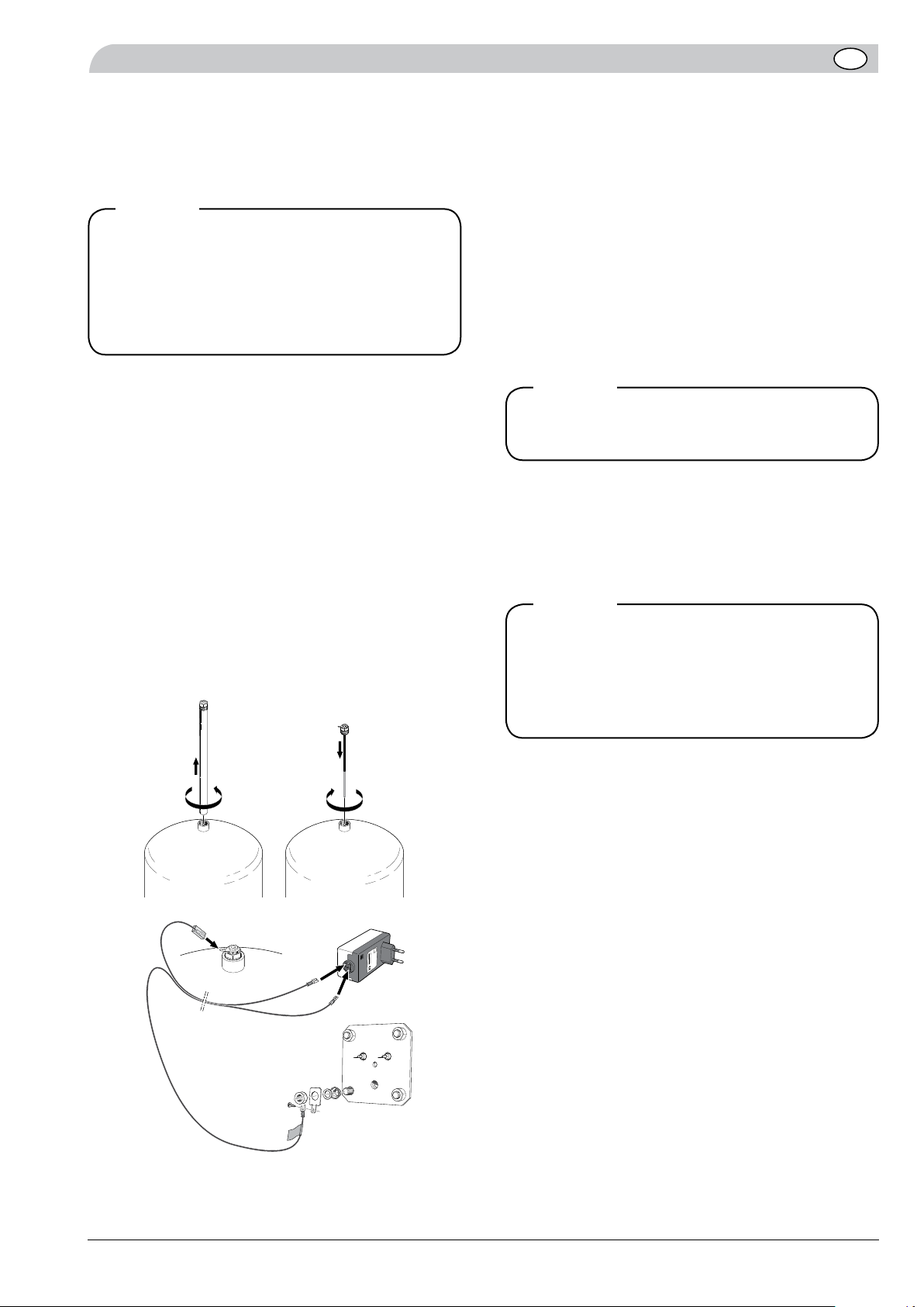
Kontroll av isolering
a) Titananod
Förfarande: Ställ in instrumentet för resistansmätning.
Töm beredaren, så att vattnet inte orsakar elektrisk
överledning. Anslut instrumentets elektroder till titana-
noden och den emaljerade beredaren.
Läs av resistansen.
Nominellt värde: Hög resistans (1 kΩeller mer).
Avvikelser från nominellt värde: För kortsluten titananod
är resistansen nära noll.
Mätningar
De nedan beskrivna mätningarna utförs vid felsökning.
Eventuella avvikelser från nominella värden tyder på att
systemet installerats felaktigt.
Mätning av drivspänning
Sätt instrumentets mätområdesväljare till området
20 VDC. Anslut instrumentets pluselektrod till anoden
och minuselektroden till beredaren.
Nominellt värde: Minst + 2,3 VDC. Beroende på vattnets
konduktivitet kan drivspänning mellan cirka 2,3 och
cirka 5 V anses normal. Om vattnet har mycket ringa
konduktivitet kan drivspänningen vara högre.
Avvikelser från nominellt värde: Högre drivspänning
(upp till 10 V) kan tyda på icke isolerad värmeväxlare av
metall. Om drivspänningen är nära noll fungerar inte
det katodiska korrosionsskyddet. Detta kan inträffa om
titananoden är kortsluten till beredaren, exempelvis till
följd av defekt tätning eller om anoden är i kontakt med
komponenter inne i tanken.
Mätning av skyddsström
Förfarande: Sätt instrumentet till mätområde 200 el-
ler 20 mA och anslut det i serie mellan den nätanslutna
spänningsomvandlaren och tanken, eller mellan den
nätanslutna spänningsomvandlaren och anoden.
Nominellt värde: Vid normal emaljering och om inga
ytterligare komponenter finns, är värden lägre än 10
mA normala för vanlig dricksvattenkvalitet. Det faktiska
värdet påverkas också av tankens storlek.
Avvikelser från nominellt värde: Höga strömmar, i syn-
nerhet 10 mA eller mer, kan tyda på stora emaljskador
eller på att icke emaljerade komponenter med otill-
räcklig isolering är kortslutna. Om skyddsströmmen
är noll fungerar inte det katodiska korrosionsskyddet.
Kontrollera anslutningskabeln och kontakterna.
För dessa kontroller krävs en digital multi-
meter.
OBS!

10 ICP 10
SE
Till Installatören
Tekniska data
Tekniska data
Nätmatning 230 V 50/60 Hz
Nominell effekt VA < 4
Nominell drivspänning V 2,3
Nominell ström (sekundär) mA 100
Drivspänning (sekundär) max. 10 V vid 100
Temperatur (nätansluten spänningsomvandlare) °C 0–40
Skyddsklass II
Kapslingklass IP20
Längd (utan nätstickkontakt) mm 100
Bredd (utan nätstickkontakt) mm 50
Höjd (utan nätstickkontakt) mm 40
Längd elektrod mm ca 400
Diameter elektrod mm 3
Vikt (utan anodkabel) g ca 200

11ICP 10
General
ICP 10 is a direct current anode for corrosion protection
for enamelled water heaters such as NibeCompact and
Nibe Eminent, and internal heaters in VPB and F1245.
The anode consists of a potentiostat for connection to
the mains and a supply and reference electrode. The
electrode is coated with titanium, which is practically
wear free in current conduction.
Principle of operation
The ICP 10 system consists of a voltage inverter and a
titanium anode, connected by a cable. The system is
powered from the voltage inverter and the protective
current is led to the heater wall through the titanium
anode. The electrochemical reactions that take place at
the titanium anode (positive pole) and any damage to
the water heater enamel, which is in contact with the
water and functions as a cathode (negative pole), means
that electrons move towards the enamel damage. This
means that the electrochemical surface potential of
enamel damage in contact with water is reduced so
much that corrosion of the heater wall steel is practically
non-existent. Depending on the water quality, calcium
deposits can also build up on damaged enamel.
The system functions as an open circuit potentiostat,
which means that the protective current that flows
through the titanium anode is regularly briefly interrupt-
ed.
During these interruptions the potential difference be-
tween the titanium anode and the water heater inner
wall is measured, and this voltage is transferred to the
voltage converter and compared there to the set voltage
(set point voltage). The protective current is adjusted so
that the actual potential difference (actual voltage) cor-
responds with the set point voltage.
Contents
1 x titanium anode
1 x voltage inverter
1 x cable
1 x ground plate with screw
Correx Up 2.3-919 fits the following:
Compact-E
Eminent-E
Fighter 315
VPA 300/200-E
VPA 450/300-E
VPB 200-E
F1245-E
INSTALLATION AND MAINTENANCE INSTRUCTIONS
Direct-current anode

12
GB Maintenance routines
Operation and maintenance
In practical terms the surface of the titanium anode
does not wear at all. Check the indicator lamp at least
once a month.
Indicator lamp green
ICP 10 in operation.
Indication lamp out
Contact your installer.
Indication lamp flashing red
Contact your installer.
Safety instructions for operation
• The ICP 10 system must be in operation during pe-
riods when one does not lose any water, for exam-
ple during vacations, otherwise it does not give the
necessary corrosion protection.
• The water heater should not be run for more than
two months without the water being drained, there
is a risk of gas build up, which often reveals itself in
the form of gurgling noises in the tank and pipes.
Safety warnings regarding water heaters with im-
mersion heater
If the immersion heater which is insulated is defective,
there is a risk that the water will conduct voltage to
the metal parts of the heater that are not protected.
Touching these parts could then be fatal. To prevent
this, the immersion heater must be regularly inspected
by an authorised electrician, to ensure that the immer-
sion heater functions correctly and safely.
Electrical installation and service must be
carried out under the supervision of a qual-
ified electrician. Electrical installation and
wiring must be carried out in accordance
with the stipulations in force.
NOTE!
ICP 10

13
GB
General points for the installation engineer
Cut the power to the heat pump/water
heater before starting work.
NOTE!
Handling
• If post installing, any existing magnesium sacrificial
anodes are removed before ICP 10 is installed.
• Never connect the voltage inverter for mains con-
nection to the magnesium sacrificial anodes.
• The titanium anodes must not come into direct con-
tact with components in the heater or the inside of
the heater.
• Only use the cables supplied for connection.
• The function of the ICP 10 system is only guaran-
teed if all electrical components are correctly metal-
lically connected.
• Check that the cables are correctly connected be-
fore starting. Incorrectly connected cables cause
increased corrosion.
If ICP 10 is post installed any existing
threaded sleeves with reducers of galva-
nised steel can be used, if so required.
Any opening of system components, for
example connection cables, invalidates the
guarantee.
NOTE!
General points for the installation
engineer
The direct current anode may only be used in sealed and
dry areas.
All electrical connections behind covers
secured by screws must be carried out by an
authorised electrician.
NOTE!
ICP 10

14
GB Connection
Installing the complete anode in the
threaded sleeve
Installation instructions for the screw mounting kit and
titanium anode.
Area of use
The mounting kit is used to install the titanium anode
screwed mounting kit threaded G 3/4’’. The titanium an-
ode must be mounted on the screw mounting kit before
it is installed.
Mounting
1. Thread the elastic red brown seal ring over the
thread on screw M8 x 30 of the titanium anode, so
that the ring rests against the titanium anode seal
washer. Only use the sealing material supplied.
2. Secure the screw in the screw mounting by inserting
the insulating sleeve over the screw threaded sec-
tion with the seal ring.
3. Insert the screw, with sealing ring and insulation
sleeve, through the hole in the screw mounting
until the seal is against the screw mounting and the
screw is centred.
4. Insert the diode plate on the screw so that the un-
derside (with the large connector ring) is inside the
screw mounting.
The LED plates upper and lower sides are
not the same. If the LED plate is placed
upside down the red LED will flash to indi-
cate a function fault.
NOTE!
The screwed mounting must be sealed.
Pressure test the screw mounting before
the unit is installed in the tank.
NOTE!
5. Install the washer above the LED plate.
6. Screw the galvanised M8 nut onto the screw and
tighten it to 6 Nm using a torque wrench.
7. Install the toothed washer with the flat pin connec-
tor which is locked using the galvanised lock nut
M8. The screw mounting must be held tight, in a
vice for example. Tighten the M8 nut.
ICP 10

15
GB
Connection
LEK
LEK
LEK
LEK
Installation of ICP 10 system for threaded
sleeve installation
1. Drain the heater, if so needed.
2. Remove any existing magnesium sacrificial anodes.
3. Screw in the titanium anode and install the ground
washer.
4. Place the forked cable terminal on the cable marked
ground connection on the ground washer.*
5. Install the switch on the titanium anode flat pin of
the connection cable on the flat pin.
6. Insert the two connectors on the other end of the
connection cable to the potentiostat terminal in the
lead-in on the mains connected voltage inverter.
Position the larger female connector (6.3 x 0.8 mm)
on the larger flat terminal and the smaller (4.8 x 0.8
mm) on the smaller flat terminal in the mains con-
nected voltage inverter.
7. Fill the heater with water and check that it is sealed.
8. Note the indicator lamp on the voltage inverter
housing.
The threaded sleeve is supplied with a PTFE
seal ring. If this seal ring is damaged the
joint must be sealed with thread sealant,
such as tow or PTFE thread tape.
NOTE!
Function check
Function check LED plate
1. Check that the LED plate is correctly installed using
a multimeter. The measurement equipment must be set
for LED testing. When the LED plate is correctly installed
the instrument must indicate an open circuit (several
megaohms, which corresponds to blocking direction)
when the positive electrode is put against the M8 nut
and the negative electrode against the threaded con-
nection.
Function check, anode
2. Check the polarity. The operating voltage U must
exceed +2.3 VDC. This measurement must be made
with the tank filled with water and the mains connected
voltage inverter connected.
• Indicator lamp green: Mains voltage is connected and
ICP 10 is ready for operation.
• Indicator lamp out: Probably no mains voltage.
• Indicator lamp flashes red: Function fault in the sys-
tem.
ICP 10 is only active when the tank is filled
with water.
NOTE!
If the indicator lamp starts to flash immedi-
ately after installation it is probably due to
incorrect installation. To fault-trace see the
section Dealing with malfunctions.
NOTE!
ICP 10

16
GB Dealing with malfunctions
Dealing with malfunctions Indication lamp out
• Mains supply failure.
Indicator lamp flashes red
First reset the voltage inverter by unplugging from
the mains supply, waiting about 30 seconds and then
plugging it in again. This creates a well defined output
relationship.
• No or too little water in the hot water tank.
• Insufficient electrical connection between the mains
connected voltage inverter and anode/heater.
• Insufficient insulation between the electrode and
the heater wall, or mounting components.
• Insufficient insulation of the titanium anode as a
result of a sealing fault.
• Incorrect polarity in the connection cable.
In normal operation the anode should be the pos-
itive and the tank should be the negative. Check
that the LED plate is correctly located in the installa-
tion kit.
• Cable breakage in the connection cable.
When the tank is empty the resistance
between the titanium anode and the tank
must be high, theoretically infinite.
NOTE!
Malfunctions in the ICP 10 are usually indicated by the
indicator lamp on the voltage inverter housing flashing
red.
Many faults can be identified by checking
the system direct current, current, polar-
ity, insulation and resistance, and easily
resolved. Disconnect any immersion heaters
from the mains. The checks described may
only be carried out by authorised
electricians.
NOTE!
In the event of malfunction or operating disturbances first check the points below:
ICP 10

17
GB
Dealing with malfunctions
cathodic corrosion protection does not function. Check
the connection cable and connections.
Polarity check
Procedure: Connect the instrument’s positive electrode
to the anode and the negative electrode to the heater.
Nominal value: Operating voltage >/= + 2.3 VDC. The
instrument must indicate positive voltage.
Deviations from nominal values: If the value has the
wrong signs (for example -2.5 V), the polarity is wrong,
which increases the risk of heater corrosion. Switch off
ICP 10 immediately and contact the installer.
Checking the insulation
a) Titanium anode
Procedure: Set the instrument to resistance measure-
ment. Drain the heater, so that the water does not
cause electrical conduction. Connect the instrument’s
electrodes to the titanium anode and the enamelled
heater.
Read off the resistance.
Nominal value: High resistance (1 kΩor more).
Deviations from nominal values: The resistance of a
short-circuited titanium anode is zero.
Measurements
The following measurements are carried out when fault
tracing. Any deviations from the nominal values indicate
that the system has been incorrectly installed.
Measuring operating voltage
Set the measurement range selector of the instrument
to 20VDC. Connect the instrument’s positive electrode
to the anode and the negative electrode to the heater.
Nominal value: Minimum + 2.3 VDC. Depending on the
conductivity of the water, operating voltage between
approx 2.3 and 5 V can be considered normal. If the
water has very low conductivity the operating voltage
may be higher.
Deviations from nominal values: Higher operating volt-
age (up to 10 V) can be due to non insulated metal
heat exchanger. If the operating voltage is close to zero
the cathodic corrosion protection does not work. This
can happen if the titanium anode is short circuited to
the heater, for example as a result of a defective seal or
if the anode is in contact with components inside the
tank.
Measuring protective current
Procedure: Set the instrument to measurement range
200 or 20 mA and connect it in series between the
mains supplied voltage inverter and the tank, or be-
tween the mains supplied voltage inverter and the
anode.
Nominal value: With normal enamel and if there are no
other components, values lower than 10 mA are normal
for normal drinking water. The actual value is affected
by the size of the tank.
Deviations from nominal values: High currents, 10 mA
or higher, can indicate large enamel damage or that
non-enamelled components with insufficient insulation
are short circuited. If the protective current is zero the
A digital multimeter is required for these
checks.
NOTE!
ICP 10

18
GB Technical Data
Technical data
Mains supply 230 V 50/60 Hz
Nominal output VA < 4
Nominal operating voltage V 2,3
Nominal current (secondary) mA 100
Operating voltage (secondary) max. 10 V at 100
Temperature (mains connected voltage inverter) °C 0–40
Protection class II
Enclosure class IP20
Length (without mains plug) mm 100
Width (without mains plug) mm 50
Height (without mains plug) mm 40
Length electrode mm approx. 400
Diameter electrode mm 3
Weight (without anode cable) g approx. 200
ICP 10

19ICP 10
Allgemeines
ICP 10 ist eine Fremdstromanode zum Korrosionsschutz
emaillierter Brauchwasserspeicher wie NibeCompact
und Nibe Eminent sowie Innenspeicher in VPB und
F1245.
Die Anode verfügt über einen Potentiostat zum
Stromanschluss sowie über eine Versorgungs- und
Referenzelektrode. Die Elektrode ist mit Titan beschich-
tet und somit bei Stromdurchgang praktisch verschleiß-
frei.
Funktionsprinzip
Das ICP 10-System besteht aus einem
Spannungswandler und einer Titananode, die mit ei-
nem Kabel verbunden sind. Das System wird vom
Spannungswandler versorgt und der Schutzstrom wird
durch die Titananode zur Speicherwand geleitet. Die
elektrochemischen Reaktionen, die an der Titananode
(Pluspol) stattfinden sowie eventuelle Schäden an der
Emaille des Brauchwasserspeichers, die im Kontakt
mit dem Wasser stehen und als Kathode fungie-
ren (Minuspol), sorgen dafür, dass die Elektronen in
Richtung Emailleschäden wandern. Dies bedeutet,
dass das elektrochemische Oberflächenpotenzial bei
Emailleschäden durch Wasserkontakt so weit gesenkt
wird, dass die Korrosion des Speicherwandstahls na-
hezu zum Erliegen kommt. Je nach Wasserqualität
kann es bei Emailleschäden darüber hinaus auch zu
Kalkablagerungen kommen.
Das System funktioniert als so genannter
Unterbrechungspotentiostat. Das bedeutet: Der
Schutzstrom, der durch die Titananode fließt, wird re-
gelmäßig kurzzeitig unterbrochen.
Während dieser Unterbrechungen wird der
Potenzialunterschied zwischen Titananode und
Innenwand des Brauchwasserspeichers gemessen. Diese
Spannung wird zum Spannungswandler überführt und
dort mit der eingestellten Spannung (Sollspannung) ver-
glichen. Daraufhin wird der Schutzstrom justiert, sodass
der tatsächliche Potenzialunterschied (Istspannung) mit
der Sollspannung übereinstimmt.
Inhalt
1 x Titananode
1 x Spannungswandler
1 x Kabel
1 x Erdungsplatte mit Schraube
Correx Up 2.3-919 ist ausgelegt für:
Compact-E
Eminent-E
Fighter 315
VPA 300/200-E
VPA 450/300-E
VPB 200-E
F1245-E
MONTAGE- UND WARTUNGSANLEITUNG
Fremdstromanode

20
DE Wartungsroutinen
Betrieb und Wartung
Die Oberfläche der Titananode verschleißt praktisch
kaum. Überprüfen Sie die Anzeigelampe mindestens
einmal monatlich.
Anzeigelampe grün
ICP 10 ist in Betrieb.
Anzeigelampe leuchtet nicht
Wenden Sie sich an Ihren Installateur.
Anzeigelampe blinkt rot
Wenden Sie sich an Ihren Installateur.
Sicherheitsvorschriften für den Betrieb
• Das ICP 10-System soll selbst dann in Betrieb sein,
wenn kein Wasser entnommen wird. Beispielsweise
während eines Urlaubs. Ansonsten wird nicht der
erforderliche Korrosionsschutz erzielt.
• Der Brauchwasserspeicher sollte nicht mehr als
zwei Monate in Betrieb sein, ohne dass Wasser
entnommen wird. Ansonsten besteht die Gefahr
einer Gasbildung. Diese zeigt sich häufig durch
Luftgeräusche in Speicher und Leitungen.
Sicherheitswarnungen für den
Brauchwasserspeicher mit Elektroheizpatrone
Ist die abisolierte Elektroheizpatrone defekt, besteht
die Gefahr, dass das Wasser die Spannung zu den
Metallkomponenten des Speichers leitet, die nicht
gegen Berührungen geschützt sind. Eine Berührung
solcher Komponenten kann zu Stromunfällen führen.
Um dies zu verhindern, müssen die Elektroheizpatronen
regelmäßig von einem befugten Elektroinstallateur
inspiziert werden, um eine einwandfreie und sichere
Funktionsweise sicherzustellen.
Elektrische Installation sowie eventuelle
Servicearbeiten müssen unter Aufsicht eines
ausgebildeten Elektroinstallateurs erfol-
gen. Bei der Elektroinstallation und beim
Verlegen der Leitungen sind die geltenden
Vorschriften zu berücksichtigen.
Hinweis:
ICP 10
Other manuals for ICP 10
1
Table of contents
Languages: