Nicotra DDMP Series User manual
1
Rev. 2 – 10
th
November2015
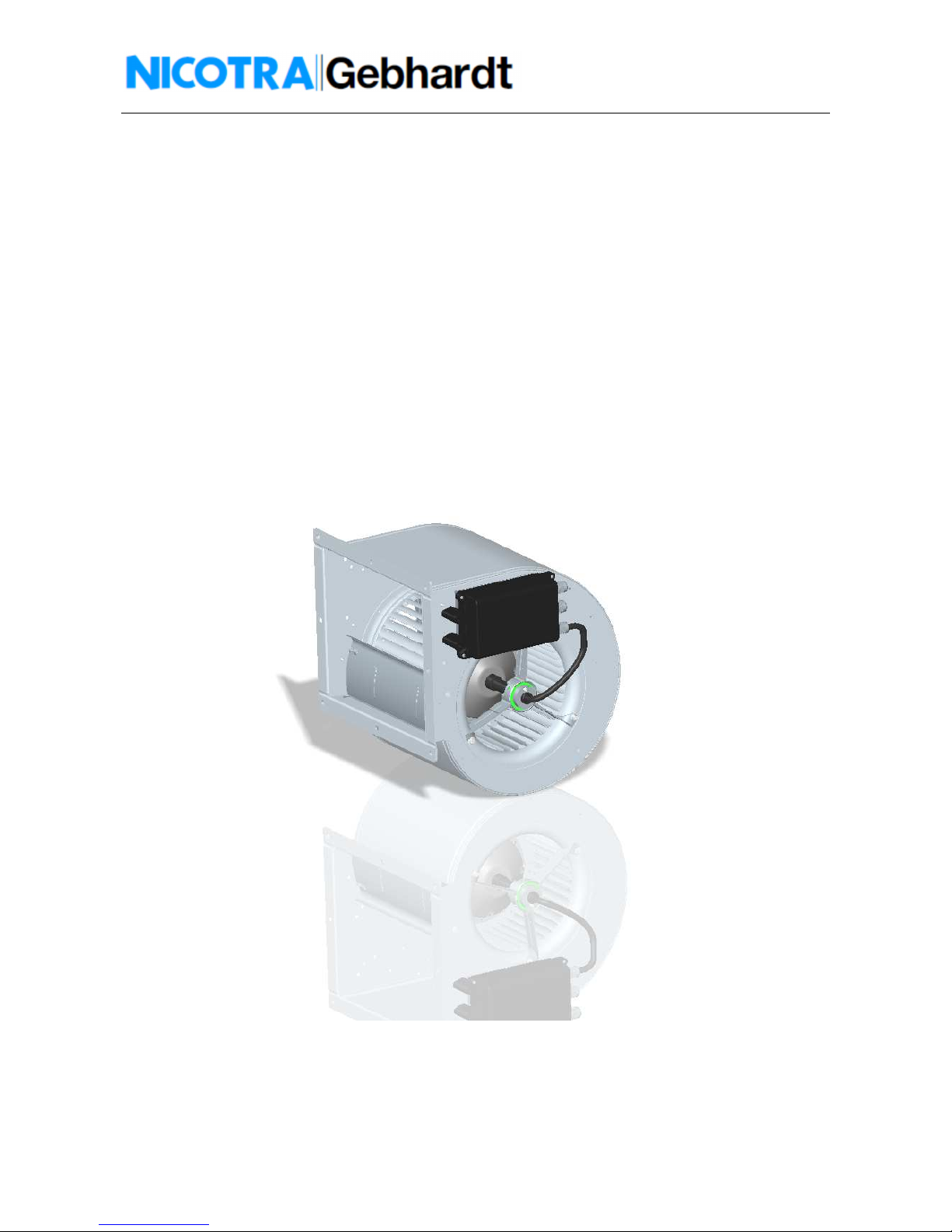
DDMP FAN
Operating Manual
2
Rev. 2 – 10
th
November2015
Definition and Warning
Warning For the purpose of this documentation and the product warning labels,
"Warning" indicates that death, severe personal injury or substantial damage to property
can result if proper precautions are not taken.
Caution For the purpose of this documentation and the product warning labels, "Caution"
indicates that minor personal injury or material damage can result if proper precautions
are not taken.
Note For the purpose of this documentation, "Note" indicates important information
relating to the product or highlights part of the documentation for special attention.
Qualified per onnel
For the purpose of this Instruction Manual and product labels, a "Qualified person" is someone who is
familiar with the installation, mounting, start-up and operation of the equipment and the hazards in ol ed.
He or she must ha e the following qualifications:
Trained and authorized to energize, de-energize, clear, ground and tag circuits and equipment in
accordance with established safety procedures.
Trained in the proper care and use of protecti e equipment in accordance with established safety
procedures.
Trained in rendering first aid.
U e for intended purpo e only
The equipment may be used only for the application stated in the manual and only in conjunction with
de ices and components recommended and authorized by Nicotra Gebhardt.
Read carefully
efore installing and commissioning the DDMP fan, you must read all safety instructions
and warnings carefully including all the warning labels attached to the equipment. Make
sure that the warning labels are kept in a legible condition and replace missing or
damaged labels.
NICOTRA Gebhardt reserves the right to change without notice.
Information i al o available from:
Nicotra Gebhardt S.p.A. Telephon: +39 035 873 111
Via Modena, 18 Telefax: +39 035 884 319
24040 Ci erano Loc. Zingonia (BG)
Italy E-mail: presales.italy@nicotra-gebhardt.com

3
Rev. 2 – 10
th
November2015
Safety In truction
The following warnings, cautions and notes are pro ided for your safety and as a means of pre enting
damage to the product or components at the connected machines. This section lists warnings, cautions and
notes, which apply generally when handling the Nicotra Gebhardt Dri er, classified as General, Tran port
& Storage, Commi ioning, Operation and Repair.
Specific warning , caution and note that apply to particular acti ities are listed at the beginning of the
rele ant chapters and are repeated or supplemented at critical points throughout these sections.
Plea e read the information carefully, ince it i provided for your per onal afety and will al o help
prolong the ervice life of your DDMP fan.
General
This equipment contains dangerous voltages and controls potentially dangerous rotating
mechanical parts. Non-compliance with these warnings or failure to follow the
instructions contained in this manual can result in loss of life, severe personal injury or
serious damage to property.
Only suitable qualified personnel should work on this equipment, and only after becoming
familiar with all safety notices, installation, operation and maintenance procedures
contained in this manual. The successful and safe operation of this equipment is
dependent upon its proper handling, installation, operation and maintenance.
Children and the general public must be prevented from accessing or approaching the
equipment!
Risk of electric shock! The DC– US capacitors remain charged after mains supply has been
switched off. It is not permissible to open the equipment until 10 minutes after the mains
supply has been removed.
This equipment may only be used for the purpose specified by the manufacturer.
Unauthorized modifications and the use of spare parts and accessories that are not sold
or recommended by the manufacturer of the equipment can cause fires, electric shocks
and injuries.
Keep these operating instructions within easy reach of the equipment and make them
available to all users. Whenever measuring or testing has to be performed on live
equipment suitable electronic tools should be used.
efore installing and commissioning, please read these safety instructions and warnings
carefully and all the warning labels attached to the equipment.
Make sure that the warning labels are kept in a legible condition and replace missing or
damaged labels.
4
Rev. 2 – 10
th
November2015
Tran port & Storage
Correct transport, storage, erection and mounting, as well as careful operation and
maintenance are essential for proper and safe operation of the equipment.
Protect the DDMP fan against physical shocks and vibration during transport and storage.
Also be sure to protect it against water (rainfall) and excessive temperatures.
Commi ioning
Work on the device/system by unqualified personnel or failure to comply with warnings
can result in severe personal injury or serious damage to material.
Only suitably qualified personnel trained in the setup, installation, commissioning and
operation of the product should carry out work on the device/system.
This equipment must be grounded.
The following terminals can carry dangerous voltages even if the Driver is inoperative:
the power supply terminals L, N
the motor terminals U, V, W
Operation
The Driver must NOT be removed from the related DDMP fan type and size.
The Driver can’t be used separate from the related fan.
Ensure correct grounding connections. The ground cable must be sufficient to carry the
maximum supply fault current which normally will be limited by the fuses or MC .
Suitably rated fuses or MC should be fitted in the mains supply to the inverter, according
to any local legislation or codes.
The Driver operates at high voltages.
Certain parameter settings may cause the inverter to restart automatically after an input
power failure.
Repair
Repairs on equipment may only be carried out by Nicotra Gebhardt.
efore opening the equipment for access, disconnect the power supply and wait for at
least 10 minutes until the DC- US capacitor is completely discharged!
5
Rev. 2 – 10
th
November2015
Declaration of conformity
The DDMP Dri er product is conform to the rele ant safety pro isions of the Low Voltage Directi e
2006/95/EC and the EMC Directi e 2004/108/EC and has been designed and manufactured in accordance
with the following harmonized European standards:
•EN 61000-3-2 “Electromagnetic compatibility (EMC) - Part 3-2: Limits - Limits for harmonic current
emissions (equipment input current <= 16 A per phase)”.
•EN 61000-6-3 “Electromagnetic compatibility (EMC) - Part 6-3: Generic standards - Emission
standard for residential, commercial and light-industrial en ironments”.
•EN 61000-6-4 “Electromagnetic compatibility (EMC) - Part 6-4: Generic standards - Emission
standard for industrial en ironments”.
•EN 61800-3 EMC Product Standard for Power Drive Sy tem .
Electromagnetic Compatibility
The DDMP product is designed with high standards of EMC in mind. The Dri er, suitable for use within the
European Union, is fitted with an internal EMC filter. This EMC filter is designed to reduce the conducted
emissions back into the supply through the power cables for compliance with harmonised European
standards.
It is the responsibility of the installer to ensure that the equipment or system into which the product is
incorporated complies with the EMC legislation of the country of use. Within the European Union,
equipment into which this product is incorporated must comply with the EMC Directi e 2004/108/EC.
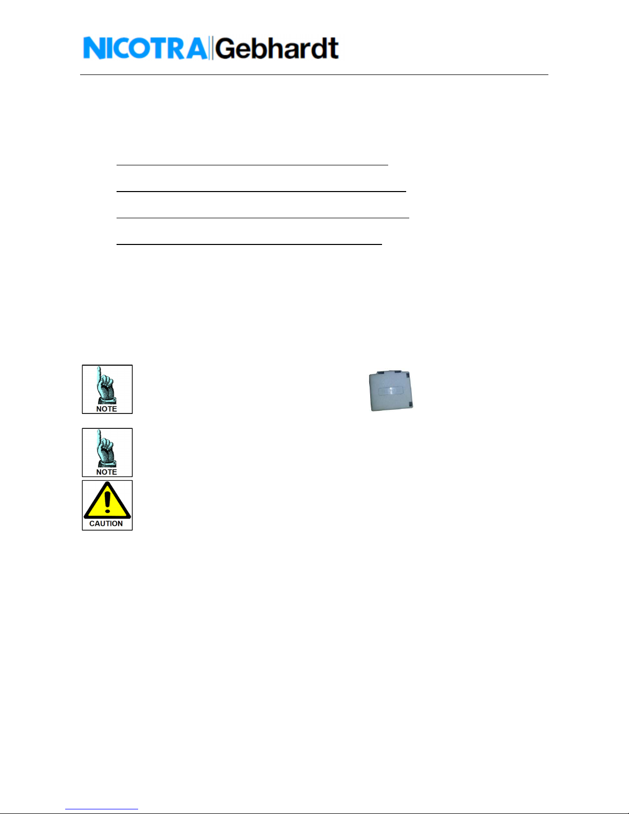
To improve the Electromagnetic compatibility
A ferrites model Wurth 742 717 22
can be put on the power supply cable
(close to the driver).
Fig. 1 – Ferrite model
The compliancy to the standards are intended for a single fan.
No tests have been made on multiple installations.
The zero series of the 2KW Driver (LOT 20151020 01) does not comply with the limits of
category C1 (EN 61800-3).
Further series will be compliants.
Product overview
General Information
The DDMP is a forward cur ed blade fan equipped by an external permanent magnet rotor motor. The
rotor magnets are made by rare earths (NdFeB) that strongly reduce the motor dimension and therefore
the fan obstruction. The motor shape itself has been chosen for increasing the airflow inside the fan scroll.
The Dri er is compact and it’s directly installed on board of the fan. It is equipped with an acti e PFC and it
dri es the motor through a sensorless algorithm.
6
Rev. 2 – 10
th
November2015
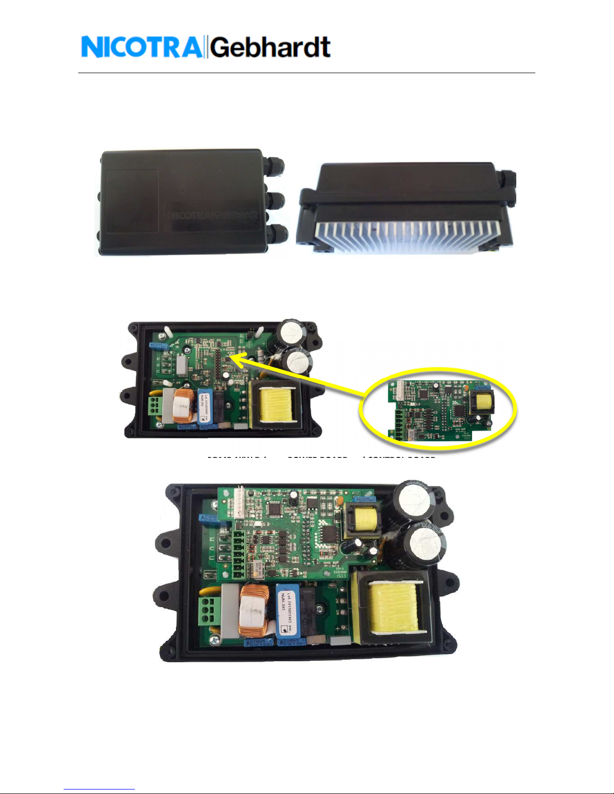
1KW Driver
In the following figures is shown the 1KW Dri er and its parts.
Fig. 2 – DDMP 1KW Driver front and ide view
Fig. 3 – DDMP 1KW Driver – POWER BOARD and CONTROL BOARD
Fig. 4 – DDMP 1KW Driver – Complete view

7
Rev. 2 – 10
th
November2015
2KW Driver
In the following figures is shown the 2KW Dri er and its parts.
Fig. 5– DDMP 2KW Driver front and ide view
Fig. 6 – DDMP 2KW Driver – POWER BOARD and CONTROL BOARD

8
Rev. 2 – 10
th
November2015
Feature
-Sinusoidal Sensorless control
-Supply oltage 230Vac
-Integrated acti e Power Factor Controller
-Simple cable connection with cage clamps
-Integrated Modbus RTU interface
-Integrated analogue interface 0-10V
-Tachometric output a ailable
Performance
-Closed-loop speed control function
-Soft start
-Adjustable limits and operating mode
-Self-protecting strategies implemented
-High efficiency
-NTC bypassed during operation
-PFC disabled at stop
-1.1 KW and 2.1 KW maximum input power
-Power Factor >95%
Protection
-Missing phase protection
-Short circuit protection
-O erload protection
-O erheat protection
-Impeller blocking protection
-Safe Operating Area (speed, power and current limitation)
Fig. 7 – Safe Operating Area
Ambient Operating Condition
-Protection Class: IP 44
-Humidity Range: 90% non-condensing
-Altitude: if the fan is to be installed at an altitude > 1000m, derating is required.
-Shocks: do not drop the Dri er or expose it to sudden shock.
-Vibration: do not install the Dri er in an area where it is likely to be exposed to constant ibrations.

9
Rev. 2 – 10
th
November2015
Connection
Work on the device/system by unqualified personnel or failure to comply with warnings
can result in severe personal injury or serious damage to material.
Only suitably qualified personnel trained in the set-up, installation, commissioning and
operation of the product should carry out work on the device/system. This equipment
must be grounded.
The following terminals can carry dangerous voltages even if the Driver is inoperative:
the power supply terminals L, N
the motor terminals U, V, W
The DDMP dri er connections are shown in figure 8 (1KW dri er) and 9 (2KW dri er).
-The motor is already connected to the Dri er by the operators Nicotra||Gebhardt
-The end user ha e to connect the power supply cable
-The end user ha e to connect the command signal to the control board
Fig. 8 – 1KW Driver connection terminal
Fig. 9 – 2K Driver connection terminal
The grounding cable/metal strip connecting the Driver to the side plate of the driver must
not be disconnected.

10
Rev. 2 – 10
th
November2015
Power upply connection:
Single Phase 230V (tolerance ± 10%) frequency 50/60Hz (Fig. 10)
Fig. 10 – Driver – POWER SUPPLY connection
Control Board connection:
As default the Dri er is programmed for an analog input command of 0-10V (Fig. 11).
The analog input can accept also a PWM signal with f>1kHz.
Fig. 11 – Driver – CONTROL BOARD analog connection
In figure 12 is shown the Modbus connection diagram.
Fig.12 – Driver – CONTROL BOARD modbu connection
Don’t use devices having the signal GND connected to the NEUTRAL cable of the power
supply. The driver may be damaged or not functioning properly.
11
Rev. 2 – 10
th
November2015
To set the speed through the Modbus protocol is necessary to set a dedicated register
(Input Type – HOLDING REGISTER 34 see “ Modbus communication” paragraph )
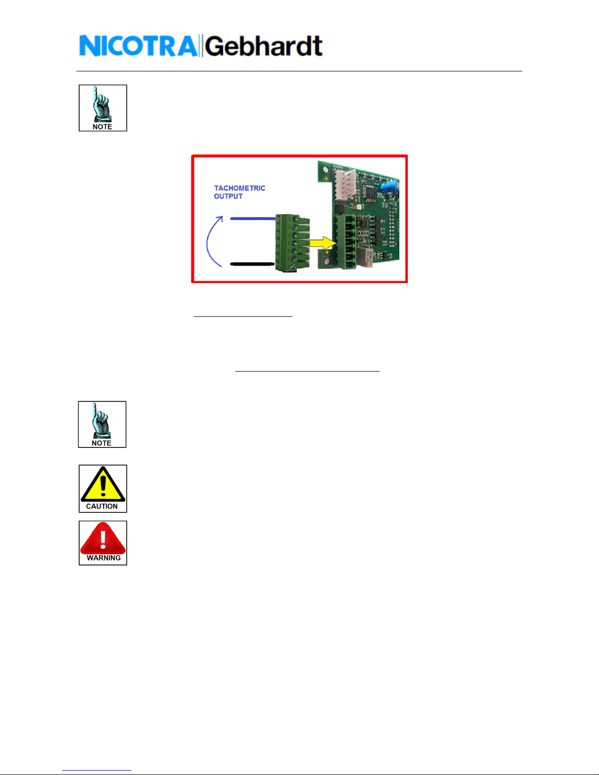
In figure 13 is shown how to connect the tachometric output.
Fig.13 – Driver – CONTROL BOARD tachometric output connection
The tachometric output is a 0 to 5V PWM wa eform at 1KHz with the following duty cycle:
!
"#$
!
%
Remember that the Speed
Real
= 0 below Speed
min
The +10V power supply available of the Driver is intended to be used with a
potentiometer of minimum 2KOhm.
Any different devices connected to it could bring to an undesired functioning of the Driver
or the connected device. The absorbed current must be <5mA.
Don’t reverse the input signal or connect the +10V to signal ground.
The Driver could be damaged.
Don’t apply signals with voltage higher than 10V
The Driver could be damaged.
12
Rev. 2 – 10
th
November2015
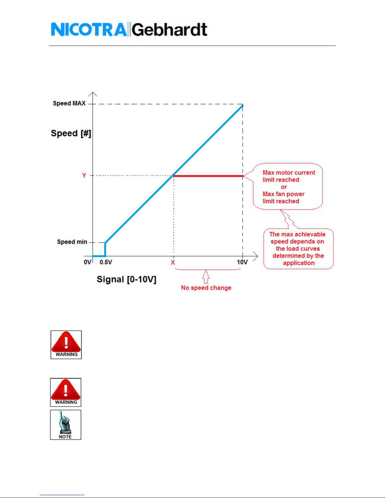
Analog Signal Command
The fan speed is proportional to the analog input oltage and the relationship is shown in figure 14.
Fig.14 – Analog ignal-Speed relation hip
The MAX and min speed default alues changes in function of the fan sizes .
In the table 1 there are all the default alues of actual DDMP series.
The MAX and min speed values are changeable via Modbus, setting the HOLDING
REGISTER 1 and 2 that are MIN RPM and MAX RPM.
Don’t set values outside the minimum and maximum RPM default value indicated in the
table 2 or possible fan wheel explosion or motor failures may occur (see “ Modbus
communication” paragraph).
Don’t set the MIN RPM higher than the MAX RPM otherwise the driver stop working
without any alarm indication!
The MIN RPM value can’t overtake the 1000rpm value

13
Rev. 2 – 10
th
November2015
A typical problem related to the fan speed is the resistances selection.
Here in the following a simple procedure for calculating them.
1) Find the
Voltage
(Required)
= V
Req
for achie ing the
Speed
(De ired)
using the diagram
Signal/Speed of figure 14.
&
'
()*+
!
"#$
!
,-&,-&
2) Reminding that ./01/2345./
6
7
8
7
9
%:;<=2
And that the analog
Input Impedance =
Z
in
=
20kOhm
&
'
:;7
9
./
6
:;7
9
!7
9
9
7
9
./
6
&
'
!:;>?:;!&
'
./
6
@
9
A;&
*'
9
./
6
:&
'
In figure 15 is shown the beha ior of the analog oltage signal increasing the potentiometer alue.
Fig.15 – Effect of the potentiometer value on the analog ignal

14
Rev. 2 – 10
th
November2015
3) With more fans regulated through the same potentiometer the pre ious formula becomes:
&
'
:;7
9
./
6
:;B7
9
!B7
9
9
In figure 16 is shown the beha ior of N fans installed din parallel.
Fig.16 – Effect of N fan in parallel
Fan performance curve de cription
The DDMP fans are tested with an installation type “B”: FREE INLET – DUCTED OUTLET.
In Fig. 17 is shown how the performances are affected by changing the fan speed and the fan load.
Fig.17 – Fan behavior by changing peed or load

15
Rev. 2 – 10
th
November2015
In figure 18 is shown an example of DDMP performance cur e using the Dri er with default setting (without
changing the MAX and min speed alues into the modbus register number 1 and 2).
In the indicated working point the correct analog oltage signal is 7V, because the Dri er automatically
limits the performance in order to make the fan work in a safe operating area (see. Fig.7 at page 8).
Therefore e en applying a oltage signal of 10V the speed of the fan doesn’t change until the analog signal
goes below 7V.
Fig.18 – Performance curve explanation – Example DDMP 9/9
16
Rev. 2 – 10
th
November2015
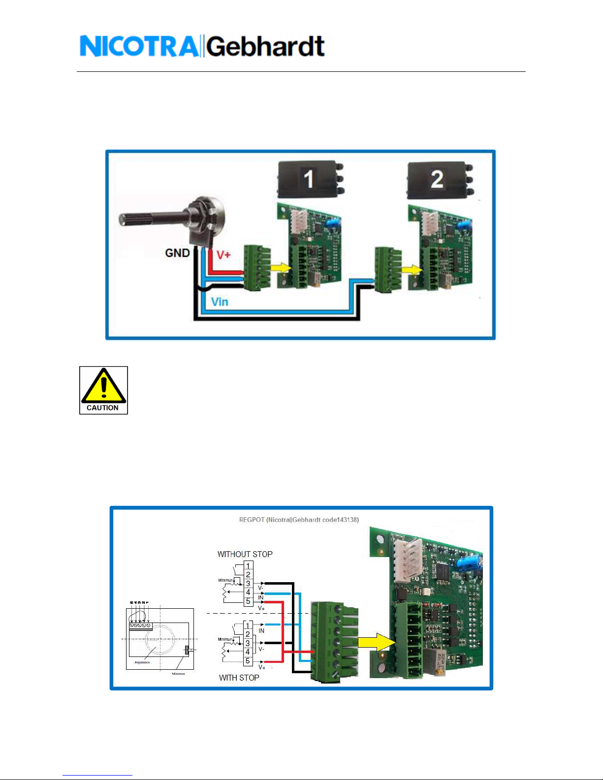
Analog ignal PARALLEL
It is possible to ha e two fans running at the same speed by applying the same analog signal.
In figure 19 is shown how to make the connection by using a potentiometer.
Fig.19 – SPEED CONTROL - PARALLEL Connection
If two or more fans are put in the same compartment it is important that they start at the
same time, otherwise the first fan running forces the other to run in backward rotation.
The DDMP fans are able to start with a low backward rotation (speed < 200rpm), but they
stops if the backward rotation is higher.
With the signal parallel this problem can be avoided.
Nicotra||Gebhardt Potentiometer
Nicotra||Gebhardt can supply a dedicated potentiometer: REGPOT code K43138 In figure 20 is shown the
connection diagrams (with stop function o without).
Fig.20 – Nicotra||Gebhardt potentiometer -REGPOT
17
Rev. 2 – 10
th
November2015
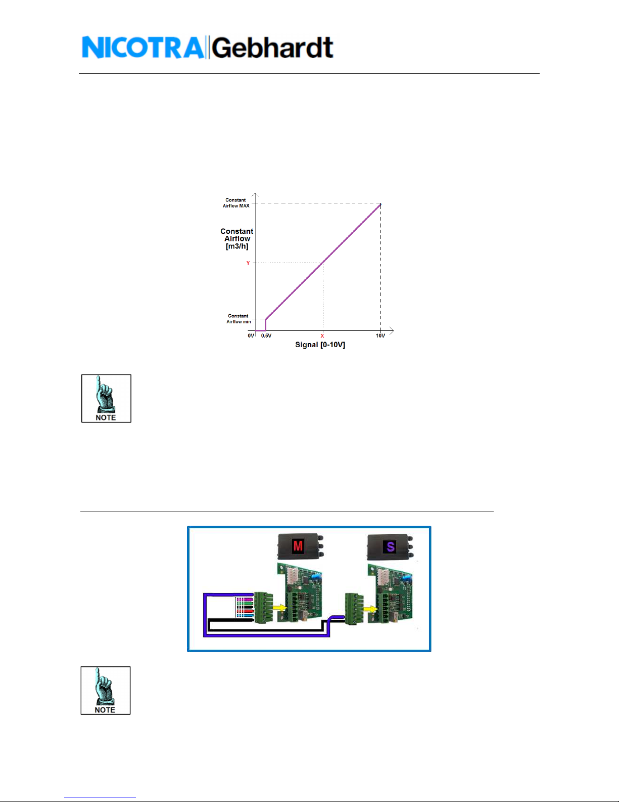
Con tant Airflow
The constant airflow mode is a ailable when the INPUT TYPE register 34 is set both at 0 or at 4. In the first
case the constant airflow is set through the Modbus by changing the Holding register parameter number 39
“CONSTANT AIRFLOW”. In the second case the constant airflow is proportional to the analog signal present
at dri er terminals.
In figure 21 it is shown the relationship between the signal and the constant airflows.
Fig. 21 – Analog Signal-Con tant Airflow relation hip
The max resolution from on constant airflow to another is +/-50m3/h.
The max precision guaranteed is SET AIRFLOW +/- 100 m3/h
In the instability areas typical of some fan sizes the constant airflow precision can’t be
guaranteed. It’s anyway suggested to work outside these areas.
MASTER/SLAVE functioning
A master and sla e configuration is possible by setting the MASTER both in Constant Airflow mode or Speed
Control and the SLAVE in Speed Control mode only.
The SLAVE Modbus Holding Register number 34 “INPUT TYPE” must be set at alue= 3 (see Modbus
communication paragraph) and in figure 22 is shown the connection diagram.
The Holding Register 46 = configuration of the OUTPUT as Tachometric or Alarm must be set at 0.
Fig. 22 – MASTER/SLAVE connection
This function is recommended when two fans work in the same plenum and in constant
airflow mode.
If the fans are set both in constant airflow driven by the same analog signal the two close
control loops interfere each other.
18
Rev. 2 – 10
th
November2015
Analog Input caled for a ignal of 0-5V
Using the Sla e configuration (“Input Type” register = 3) it is possible to dri e a fan at its max speed using a
signal 0-5V, without changing the max speed register configuration.
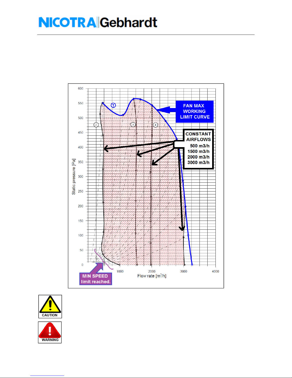
Con tant Airflow curve example
In figure 23 are shown 4 constant airflow cur es randomly chosen.
Fig. 23 – Con tant Airflow Example
It is possible to modify the max and min constant airflow values (within the limits
indicated in Table 3 pag. 23) by modifying the Modbus parameters in the holding register
42 and 43.
The max airflow (Reg. 43) must be always higher than the min airflow value (Reg. 42).

19
Rev. 2 – 10
th
November2015
Choo ing the right fan ize
Other important aspects than the fan performance when there are the fan noise and the fan efficiency.
Fan Noi e
In figure 24 is shown the indicative distribution of the Sound Pressure Level of a DDMP
model .
The DDMP fans can reach high speed compared to the std. AC fans, therefore it’s
important to evaluate the speed at the required performance to avoid noise problems
Fig.24 – DDMP Noi e di tribution – Sound Pre ure Level – Example DDMP 7/9
Fan Efficiency
In figure 25 is shown the beha ior of the Total Efficiency of a DDMP fan changing the speed (in the example
the size 7/7).
Fig.25 – DDMP Efficiency behavior – Example DDMP 7/7

20
Rev. 2 – 10
th
November2015
Driver Overheating: DERATING
When the temperature of the Dri er components o ertake a fixed threshold of 75°C the Dri er
automatically reduces the performance in order to decrease the heating.
If it is not possible to reach a steady thermal equilibrium, the Dri er shuts down.
The protection acts limiting the current to the motor .
Motor Overheating: THERMAL PROTECTOR
The motor is protected through a Thermal Protector.
If the motor temperature is too high the thermal protector open one phase and the Dri er recognize the
error and it stops the fan (see the Alarm Handling chapter).
The Motor Winding temperature and the Driver derating are dependent on the fan size
and on the fan working point.
Therefore it is possible that the fan could work at 50°C without a performance limitation
Fig.26 – DDMP thermal behavior – Example DDMP 7/9
The Driver and motor areas rated for operating in a temperature range between -20°C
and +40°C.
The derating is tested and guaranteed from +40°C to +50°C .
Higher temperatures could damage the motor winding or the performance could be
strongly reduced.
This manual suits for next models
12
Table of contents
Other Nicotra Fan manuals


Popular Fan manuals by other brands

Panasonic
Panasonic FV-08-11VFL5 installation instructions

KDK
KDK X48XG / X48XGMN Operating and installation instructions

Bosch
Bosch DRC99PS25 User manual and installation instructions

Panasonic
Panasonic WhisperCeiling FV-05 Service manual

Dyson
Dyson AM01 operating manual

Inverter
Inverter Pulsar Installation and operation instruction


Homemaker
Homemaker TX-1201D user manual

Delta
Delta breez GreenBuilder GBR80LED Installation and operating instructions

Faro Barcelona
Faro Barcelona Izaro installation guide

Concept2
Concept2 VS6033 manual

Ebmpapst
Ebmpapst D4E200-CA08-41 operating instructions

Ebmpapst
Ebmpapst D2D133-AB02-07 operating instructions