Nicotra EC FAN FDP User manual
Rev. 0 - 11/12/2020
EC FAN FDP
OPERATING MANUAL
Regal Beloit Italy S.p.A.
Via Modena, 18
24040 Ciserano (BG) ITALY
Phone +39 035 873 111
Fax +39 035 884 319
www.regalbeloit.com


Rev. 0 - 11/12/2020
OPERATING MANUALOPERATING MANUAL
ENEN
3/40
INDEXINDEX
1. DEFINITIONS AND WARNINGS ..............................................................................................................................................5
1.1 Object of this manual .........................................................................................................................................................5
1.2 Symbols used......................................................................................................................................................................5
1.3Qualiedpersonnel ............................................................................................................................................................5
1.4Useforintendedpurposeonly...........................................................................................................................................5
1.5Safetyinstrucons..............................................................................................................................................................6
1.6Informaveleer ...............................................................................................................................................................7
1.7Safeoperangarea.............................................................................................................................................................7
2. REGULATORY REFERENCES ....................................................................................................................................................8
2.1Mechanicalandelectricalsafety ........................................................................................................................................8
2.2Electro-MagnecCompability(EMC) ...............................................................................................................................8
3. DATA PLATE .............................................................................................................................................................................9
4. TRANSPORT AND STORAGE.................................................................................................................................................10
5. PACKING CONTENTS.............................................................................................................................................................10
6. UNPACKING ...........................................................................................................................................................................11
7. PRODUCT DESCRIPTION.......................................................................................................................................................11
8. TECHNICAL FEATURES..........................................................................................................................................................12
8.1Dimensionaldrawings ......................................................................................................................................................13
8.2Motor-driverconnecons...............................................................................................................................................15
9. INSTALLATION .......................................................................................................................................................................15
9.1Commissioning .................................................................................................................................................................15
9.2Operaon .........................................................................................................................................................................16
9.3Ambientoperangcondion ...........................................................................................................................................16
9.4Faninstallaon .................................................................................................................................................................16
9.5Electricalconnecons.......................................................................................................................................................17
9.5.1Powersupply............................................................................................................................................................18
9.5.2Controlboardconnecon........................................................................................................................................18
9.5.3Connecondetails ...................................................................................................................................................19
9.5.3.1Analog..........................................................................................................................................................19
9.5.3.2Modbuscommunicaon..............................................................................................................................21
9.5.3.3Tachometric,alarmandlteroutput...........................................................................................................22
9.5.3.4InputImpedances........................................................................................................................................22
10. OPERATING MODES AND SETTING OPTIONS.....................................................................................................................22
10.1Speedcontrol .................................................................................................................................................................23
10.1.1Analogspeedcontrol.............................................................................................................................................23
10.1.2Modbustemporaryspeedcontrol.........................................................................................................................23
10.1.3Modbusxedspeedcontrol ..................................................................................................................................23
10.1.4Speedcontrolcurves:examples ............................................................................................................................24
10.2Asynchronousemulaon ................................................................................................................................................24

Rev. 0 - 11/12/2020
OPERATING MANUALOPERATING MANUAL
ENEN
4/40
10.2.1Analogasynchronousemulaon ........................................................................................................................... 24
10.2.2Modbustemporaryasynchronousemulaon ....................................................................................................... 24
10.2.3Modbusxedasynchronousemulaon................................................................................................................. 24
10.2.4Asynchronousemulaoncurves:examples........................................................................................................... 25
10.3PIDclosedcontrolloop..................................................................................................................................................25
10.3.1Modbustemporaryref.PIDclosedcontrolloop.................................................................................................... 25
10.3.2Modbusxedref.PIDclosedcontrolloop ............................................................................................................. 25
10.3.3Modbusposive/negavefeedback...................................................................................................................... 26
10.4Changingtheoperaonmode.......................................................................................................................................26
11. OTHER FEATURES..................................................................................................................................................................26
11.1Filteralarm .....................................................................................................................................................................26
11.2Sostart.........................................................................................................................................................................27
12. SOA LIMITATIONS ................................................................................................................................................................. 27
12.1Speedlimitaon ............................................................................................................................................................. 27
12.2Powerlimitaon ............................................................................................................................................................. 27
12.3Outputcurrentlimitaon ............................................................................................................................................... 27
12.4Inputcurrentlimitaon ..................................................................................................................................................27
13. OTHER VARIABLES ................................................................................................................................................................ 28
13.1 Busvoltage ..................................................................................................................................................................... 28
13.2 Motorvoltage.................................................................................................................................................................28
14. DERATING AND OVERHEATING PROTECTIONS ..................................................................................................................28
14.1 Driveroverheang:DERATING .......................................................................................................................................28
14.2 Motoroverheang:THERMALPROTECTOR ...................................................................................................................28
15. MASTER & SLAVE MODE ......................................................................................................................................................29
15.1 MasterandSlave0-5VPWMout(for1.05kW-1-phaseonly)......................................................................................29
16. COMMUNICATION................................................................................................................................................................29
16.1 Temporaryholdingregister ............................................................................................................................................31
16.2 Fixedholdingregister .....................................................................................................................................................31
16.3 Holdingregisterdescripon ...........................................................................................................................................31
16.4 Inputregisterdescripon ...............................................................................................................................................36
16.5 FaninfoandModbusregisters .......................................................................................................................................37
17. ALARM HANDLING ...............................................................................................................................................................38
17.1 Monitoring......................................................................................................................................................................38
17.2 Modbusregisters-Alarmdescripon ............................................................................................................................38
17.3 BlinkingLED-Alarmdescripon ....................................................................................................................................38
17.4 Digitalalarmoutput .......................................................................................................................................................39
17.5 Alarmreset.....................................................................................................................................................................39
18. AVAILABLE SOFTWARE.........................................................................................................................................................39

Rev. 0 - 11/12/2020
OPERATING MANUALOPERATING MANUAL
ENEN
5/40
1. DEFINITIONS AND WARNINGS
1.2 Symbols used
1.3 Qualified personnel
ForthisInstruconManualandproductlabels,a"Qualiedperson"issomeonewhoisfamiliarwiththeinstallaon,mounng,
start-upandoperaonoftheequipmentandthehazardsinvolved.Heorshemusthavethefollowingqualicaons:
• Trainedandauthorizedtoenergize,de-energize,clear,groundandtagcircuitsandequipmentinaccordancewithestablished
safetyprocedures.
• Trainedinthepropercareanduseofprotecveequipmentinaccordancewithestablishedsafetyprocedures.
• Trainedinrenderingrstaid.
1.4 Use for intended purpose only
Theequipmentmaybeusedonlyfortheapplicaonstatedinthemanualandonlyinconjunconwithdevicesandcomponents
recommendedandauthorizedbyNicotra Gebhardt.
As to the "WARNING" and "CAUTION"messages,thesafetymessageisasymbol(atrianglecontaininganexclamaonmark)fol-
lowedbythetextindicangtherisklevel.Itspurposeistowarntheuserofthepotenalpersonaldamagethatmayresultfroman
incorrectuseofthemachineorfromthenon-compliancewiththeuseandmaintenanceinstrucons.
Failuretocomplywiththesesafetymessagescouldcausedamageand/ortheparalortotaldestruconoftheproductorother
equipmentconnectedtoitorharmpeople.
As to the "NOTICE"message,thesafetymessagedoesnotindicatepreciselyarisk,itisonlyforinformaon.
Pictogram Descripon
Indicatesapotenalrisksituaonthatcan
lead to death or serious damage, if it not
prevented (ex. amputaons, severe burns,
loss of vision or hearing loss or visual or
auditorysensorialimpairment).
Indicatesapotenalrisksituaonthatcould
cause less severe or minor damage, if not
prevented(ex.cuts,scratches,irritaon).
NOTICEmessage:itisusedfornon-physical
injuries.
Dangertopersonsduetoelectricity.
Theoperationswhoseexecution requires
qualified orspecializedstaff toavoidany
dangerareindicatedwiththissymbol.
WARNINGWARNING
CAUTIONCAUTION
1.1 Object of this manual
Theaimofthismanualisgivinginstruonsconcerninginstallaon,useandmaintenanceofFDPfans.
This manual refers to fans having a driver with a 5 rmware revision or higher.
Rev. 0 - 11/12/2020
OPERATING MANUALOPERATING MANUAL
ENEN
6/40
This manual is an integral part of the EC Fan FDP and it must be carefully read before using it since it gives important
indicaons with regards to its safe installaon, use and maintenance. Keep it with care.
Before using the EC Fan FDP, read carefully the following general safety rules.
• Aertakingothepackagingmakesurethatthefanisintact.Incaseofdoubtdonotuseitandcontactanauthorized
servicecentre.
• Checkthatthefanisnotdamagedinanyofitsparts.Thesafetyconceptofthefanisvalidonlyinperfectcondions.
RISK OF ELECTRICAL SHOCKS
• Anydamagedsocket,conneconterminalorcablemustbereplacedimmediatelybyqualiedtechniciansorbyauthorized
servicecentre.
• Incaseofrepairorreplacementoftheconneconcablesand/orofthedamageddevicesorthatdonotworkproperly,
pleasecontacttheauthorizedservicecentre.
• Incorrectorimproperinstallaonmaycausethesystemtomalfunconand/orresultindamagetopeopleand/orproperty.
• Alwaysdisconnectthepowersupplybeforeopeningthe fan.
Any installaon and/or maintenance tasks are only to be carried out by skilled, specialist personnel.
Exisng electrical systems must comply with the rules in force in the country where the FDP fan is installed.
Before doing any maintenance, make sure that the power supply and the baeries have been disconnected.
Install an all-pole disconnecng device in the power supply system (in accordance with IEC 60335-1 or IEC 60204-1, as
applicable).
Conform to the wiring diagrams shown in the secon “ELECTRICAL CONNECTIONS” of this manual.
Thefollowingwarnings,cauonsandnotesareprovidedforyoursafetyandhasameansofprevenngdamagetotheproductor
componentsattheconnectedmachines.
Specicwarnings,cauonsandnotesthatapplytoparcularacviesarelistedatthebeginningoftherelevantchaptersandare
repeatedorsupplementedatcricalpointsthroughoutthesesecons.
Please read the informaon carefully, since it is provided for your personal safety and will also help prolonging the service life
of your fan.
1.5 Safety instructions
WARNINGWARNING
This appliance can be used by children aged from 8 years and above and persons with reduced physical, sensory or mental
capabilies or lack of experience and knowledge on condion that they are supervised and instructed concerning use of the
appliance in a safe way and understand the hazards involved.
-> Children shall not play with the appliance
-> Cleaning and user maintenance shall not be made by children without supervision
WARNINGWARNING
The use and maintenance manual of any domesc appliance or similar device incorporang a FDP fan shall include the
following clauses.
WARNINGWARNING

Rev. 0 - 11/12/2020
OPERATING MANUALOPERATING MANUAL
ENEN
7/40
ALL RIGHTS ARE RESERVED ACCORDING TO THE
INTERNATIONAL COPYRIGHT CONVENTIONS,
Thereproduconofanypartofthismanual,inanyform,isforbiddenwithoutthepriorwrien
authorizaonofthemanufacturer.
Thecontentofthisguidecanbemodiedwithoutpriornoce.Greatcarehasbeentakenincollecngand
checkingthedocumentaoncontainedinthismanualtomakeitascompleteandcomprehensibleaspossible.
Nothingcontainedinthismanualcanbeconsideredasawarranty,eitherexpressedorimplied-including,notina
restricveway,thesuitabilitywarrantyforanyspecialpurpose.
Nothingcontainedinthismanualcanbeinterpretedasamodicaonorconrmaonoftheterms
ofanypurchasecontract.
The Nicotra Gebhardt productshavenotbeenconceivedtoworkinareasatriskofexplosions.Incaseofdamageormal-
funcon,theFDPfansmustnotbeusedunltheCustomerCareTechnicalServicehasrepairedit.
Theinstallerandthemaintenancemanmustknowthecontentofthismanual.Althoughthemainfeaturesoftheequipmentdescribed
inthismanualarenotsubjecttochange,themanufacturerreservestherighttomodifythecomponents,detailsandaccessories
itdeemsnecessarytoimprovetheproductortomeetmanufacturingorcommercialrequirementsatanymeandwithoutbeing
obligedtoupdatethismanualimmediately.
1.6 Informative letter
WARNINGWARNING
The original conguraon of the fan must not be changed at all, except as prescribed in this manual.
On receiving the fan, make sure the supply corresponds to what has been ordered.
In case of non-compliance immediately inform the manufacturer.
Also make sure the FDP fan has not been damaged during transport.
For informaon concerning the nearest supporng center, please get in touch with your retailer.
WARNINGWARNING
1.7 Safe operating area
Thedriversareprotectedagainstoverloadcondionsandasafeoperangareaisdenedbyalimitofspeed,outputpowerand
motorcurrent.
FormoredetailsrefertotheANNEX"AnalogSignalConsideraons".
Customer Care Technical Service

Rev. 0 - 11/12/2020
OPERATING MANUALOPERATING MANUAL
ENEN
8/40
2. REGULATORY REFERENCES
ThesefanswithECdrivesystemsaredesignedforincorporaoninequipment,fulllingtherequirementssetbytheMachinery
Direcve (MD - Dir. 2006/42/EU),andthosepartsoftheLow-Voltage Direcve (Dir. 2014/35/EU)whichareapplicableinaccord-
ancewiththeMD,whereitconcernselectricalsafety.
ElectricalsafetyisgenerallyachievedbyapplicaonoftheprovisionsoftheEN 60204-1 standard “Electrical equipment of ma-
chines - General requirements”.
Selectedrangesmaybedesignedtobesuitableforincorporaon(ascomponents)withinproductswhichcomplywiththestand-
ardsEN 60335-1 “Household and similar electrical appliances - Safety - General requirements” and 60335-2-40 “Household and
similar electrical appliances - Safety - Parcular requirements for electrical heat pumps, air-condioners and dehumidiers”.
Suchsafetyrequirementsarecoveredasfarasnecessaryforapartlycompletemachine,sub-assemblyorcomponent,asthesefans
arespecicallyintendedforincorporaonwithinothermachines.
Theresponsibilityforthemechanicalandelectricalsafetyoftheinstalledfanisthusofthemanufacturerofthecompletemachine
and,forthisreason,itisstrictlyforbiddentoputthefaninoperaonbeforethemanufacturerofthemachinehasassessedand
declaredthatthecompletemachinefullsalltheessenalsafetyrequirementssetforthbytheMD.
Please,checktheDeclaraonofIncorporaonwhichaccompanieseachproduct,oraskyourNicotra Gebhardtsalesrepresentave,
foraddionalinformaon.
2.1 Mechanical and electrical safety
Single-phase drive systems: FDP 1 kW,
ThedriversoftheseproductsincorporateanAcvePowerFactorControlmodule,toprovideharmonicslteringandcompliance
withtheEMCrequirementsapplicabletodomescandequivalentenvironments(“rstenvironment”),orwiththeadvancedre-
quirementsforharmonicdistoronwhichoenapplytodatacenters.
Morespecically:theycomplywiththerequirementssetin
EN 61000-6-3 – Electromagnec compability (EMC). Part 6-3:Genericstandards.Emissionstandardforresidenal,commercial
andlight-industrialenvironments.
EN 61000-6-4 – Electromagnec compability (EMC). Part 6-4:Genericstandards-Emissionstandardforindustrialenvironments
whichthisproductisincorporatedmustcomplywiththeEMCDirecve2004/108/EC.
2.2 Electro-Magnetic Compatibility (EMC)
Specic electrical safety and EMC standards are applied according to the available models of conformity declaraon
(idened as 985732, 985740 and 985748):
EMC standards
61000-6-3
(household)
61000-6-4
(industrial)
Electrical
safety
standards
60204
(machines) 985732 985748
60335
(domesc
appliances)
985740 n/a

Rev. 0 - 11/12/2020
OPERATING MANUALOPERATING MANUAL
ENEN
9/40
3. DATA PLATE
Themanufacturer’sidencaonplateislocatedonthefan.
Severalsafetywarningsareappliedtothefan;suchwarningsmustbestrictlyfollowedbyeveryonedealingwiththisproduct.
The company is not to be held responsible for damage to property or accidents to people which might occur if the above-men-
oned warnings are not observed. In such a case, the operator is the only person responsible.
Theidencaonplateislocatedonthefanscrollcase.
REF. DESCRIPTION
1 MODEL DESIGNATION
2 REGAL BELOIT ITALY CODE
3 MODIFICATION LEVEL
4 PRODUCTION LOT NO.
5 NO. PHASES & CURRENT TYPE
6 ELECTRICAL FREQUENCY
7 VOLTAGE
8 IP PROTECTION GRADE
9 MOTOR INSULATION CLASS
10 CAPACITORVALUE(WHENPRESENT)
11 MAXIMUMCURRENTINPUT
12 MOTOR RATED POWER
13 RATED RPM
To improve the Electromagnec compability a ferrite should be put on the power supply cable (close to the driver). The
compliancy to the standards is intended for a single fan. No tests have been made on mulple installaons.
The EMC tests are conducted without 485 communicaon wire, analog signals or Bluetooth devices.
WARNINGWARNING
REF. DESCRIPTION
14 THERMALPROTECTOR(Y/N)
15 OPERATING TEMPERATURE RANGE
16 UNITEXCEEDS30KG(Y/N)
17 UNITEXCEEDS85dB(A)SOUNDPOWER(Y/N)
18 OPERATING MANUAL
19 OVERALLEFFICIENCY(η)
20 EFFICIENCYCATEGORY(STATICORTOTAL)
21 MEASUREMENT CATEGORY USED TO DETER-
MINETHEENERGYEFFICIENCY(A-D)
22 EFFICIENCY GRADE AT OPTIMUM ENERGY EFFI-
CIENCY POINT
23 ErPCOMPLIANCE
24 CUSTOMERCODE(WHENAPPLICABLE)
25 PRODUCTION DATE
The compliancy to the standards are intended for a single fan.
No tests have been made on mulple installaons.
Rev. 0 - 11/12/2020
OPERATING MANUALOPERATING MANUAL
ENEN
10/40
4. TRANSPORT & STORAGE
Correct transport, storage, erecon and mounng, as well as careful operaon and maintenance are essenal for proper and
safe operaon of the equipment.
Protect the fan against physical shocks and vibraon during transport and storage. Also, be sure to protect it against water
(rainfall) and excessive temperatures.
WARNINGWARNING
If the fan must be subject to long-term storage, the storage me without applicaon of any power supply shall not exceed two
years since fan producon or since operang the fan for at least half-an-hour connuously.
The storage site shall have a temperature between -20°C and +70 °C, a Relave Humidity lower than 75%, and not be subject
to condensaon or exposed to dust.
CAUTIONCAUTION
5. PACKING CONTENTS
6xxxxx
fdp xXx xxxx xxxXXX
12345
ThefanisdeliveredinacardboardboxinsidewhichtherearetheinstallaoninstruconsandtheoponsrequiredbytheCustomer
atmeoforder.AlltheseoponswillbemounteddirectlybytheManufacturer.
Apartfromthe"opons",theCustomercanorder"accessories"aerwards.Inthiscase,theCustomerwillhavetoinstallthemby
him/herself.
Thefollowingdataareprintedonthepackingitself:
REF. DESCRIPTION
1 ART. CODE
2 MODEL DESCRIPTION
3 BATCH CODE
1
2
3

Rev. 0 - 11/12/2020
OPERATING MANUALOPERATING MANUAL
ENEN
11/40
6. UNPACKING
Check the fan. Before installing the FDP fan, check to ensure that all of the items listed are present and that there are no visible
signs of damage.
1. Removethefanfromthebox.
2. Removeallthecomponentsfromthepackaging.
WARNINGWARNING
Dispose of all packing components in compliance with the laws in force in the country of use.
RECYCLE
7. PRODUCT DESCRIPTION
Fan-Decksarecompactfans,designedtoprovidehighvolumeowrate,withsmallpressurelevels,bycombiningsidebyside
twodouble-inletforwardcurvedcentrifugalfans,driveninexpensivelybyasinglecommonelectricalmotor.Theside-by-sidefans
areed,togetherwiththemotorstand,onamounngplatewhichnormallyactsalsoasapressurebulkheadinthevenlaon
machine.
Single-impeller,aswellastripleofquadrupleversionmayalsobebuilt,forspecialrequirements.
Mounng-plate design
Besidesastandardrange,custom-specicFDfansarenormallyco-designedwithourcustomer,toprovidethebestintegraonof
thefaninthestructureofseries-producedmachines.Mounngplatesarefrequentlyused,invercalowfancoilunits,alsoas
condensaondrainagecollectors,includingadrain-pipeconnector.
TheFansofseriesFDPcombinehighenergyeciencyandlownoiselevel.Thankstothe“EC”(electroniccommutaon)motors,
theirelectronicsintegratespeedcontrolandprotecngsystem.Thisreducesthenumberofdierentcomponentsrequiredto
providethesefuncons,comparedtofanswithtradionalmotors.
ThemainfeatureofEC-motorisoperangwithoutsliplosses,whichallowconsumingsignicantlylesspowerthanconvenonal
ACmotors.
Thisoccursatallspeedlevels,especiallywithparalloadoperaon.TheECcompletedrivesystem(i.e.thecombinaonofthe
permanent-magnetmotorwithitselectronicdriver)hasamuchhigherenergyeciency,incomparisonwithadrivesystembased
onaconvenonalACmotor.
Energy saving system
• HigheciencyEC-motor
• Compactmotordesign
• Highintensityneodymiummagnets
• Noobstruconofintakeduetobuild-oncontrolunit-lessaerodynamiclosses

Rev. 0 - 11/12/2020
OPERATING MANUALOPERATING MANUAL
ENEN
12/40
REF. DESCRIPTION
1Scroll
2Inletport
3Outletport
4Rotor(forward-curvedblades)
5ECmotor
6Driver
7IDplate
General Features
• Sensorlesscontrol
• Simpleinstallaonduetoplugandplay
• Designedfordoubleinletfans
Interface
• Analogueinterfaceforspeed
control
• Full MODBUS interface com-
pliancy
High eciency of direct driven
centrifugal fan
• Integratedsoluon
• Toprangeciency
• Plugandplayoperaon
• Noneedtocongurelong
listsofinverterparameters
• Lowsoundlevel
• Highreliability
8. TECHNICAL FEATURES
Size Motor code Driver code Driver
phases
Abs. curr.
(A)
Abs. pow.
(W)
Min. temp.
(°C)
Max. temp.
(°C)
IP class
protecon
180/240 Z 1413G6 1431C1 1 Ph 2.81 A 641 W -20°C +40°C IP 32
200/190 N 1413G6 1431C1 1 Ph 2.65 A 621 W -20°C +40°C IP 32
200/190 N 1413H3 1431C1 1 Ph 4.63 A 1085 W -20°C +40°C IP 32
200/240 N 1413H4 1431C1 1 Ph 4.62 A 1069 W -20°C +40°C IP 44
200/240 N 1413H3 1431C1 1 Ph 4.62 A 1069 W -20°C +40°C IP 32
9/7 A 1413H3 1431C1 1 Ph 4.61 A 1071 W -20°C +40°C IP 32
9/9 A 1413H3 1431C1 1 Ph 4.56 A 1063 W -20°C +40°C IP 32
OtherdatarelatedtothetechnicalfeaturesarereportedontheIDplateshowninchapter3.
1
6
7
2
33
4
5
Rev. 0 - 11/12/2020
OPERATING MANUALOPERATING MANUAL
ENEN
13/40
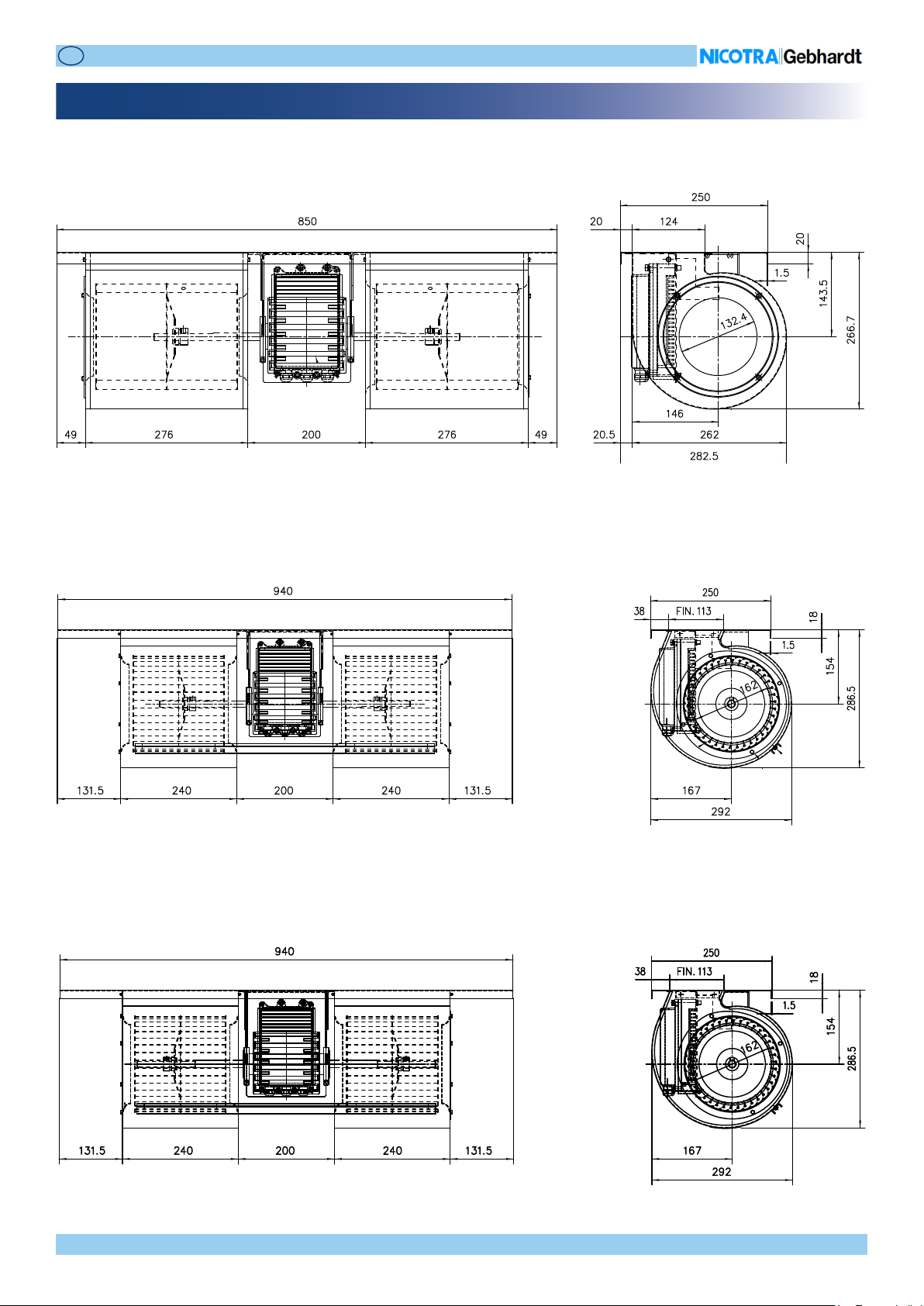
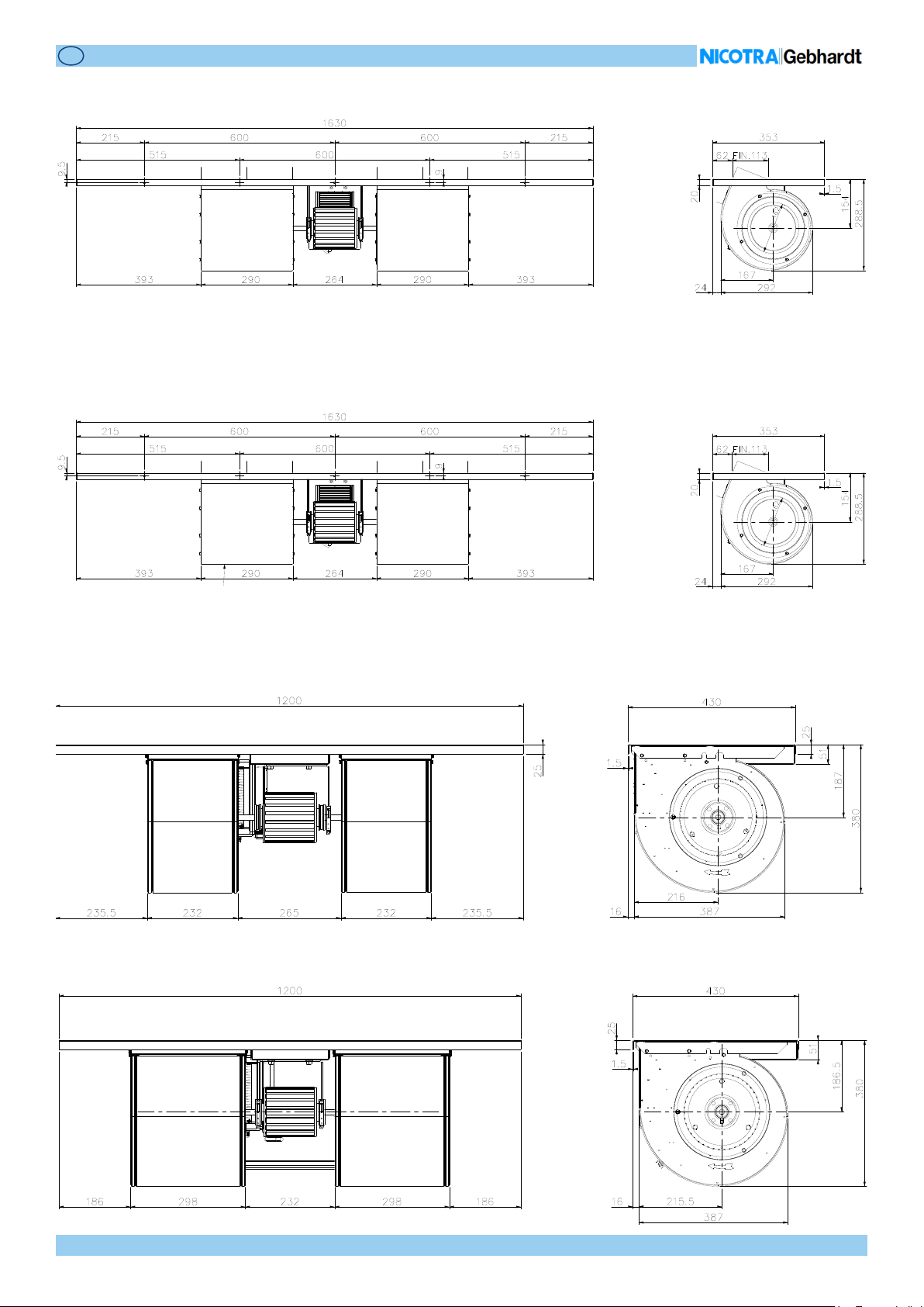
8.1 Dimensional drawings
6N4406 - FDP 180/240 Z 1413G6
6N4407 - FDP 200/190 N 1413G6
6N4408 - FDP 200/190 N 1413H3
The plate dimensions and the anchor points can be dierent.
Rev. 0 - 11/12/2020
OPERATING MANUALOPERATING MANUAL
ENEN
14/40
6N4404 - FDP 200/240 N 1413H4
6N4405 - FDP 200/240 N 1413H3
6N4409 - FDP 9/7A 1413H3
6N4410 - FDP 9/9A 1413H3
Rev. 0 - 11/12/2020
OPERATING MANUALOPERATING MANUAL
ENEN
15/40
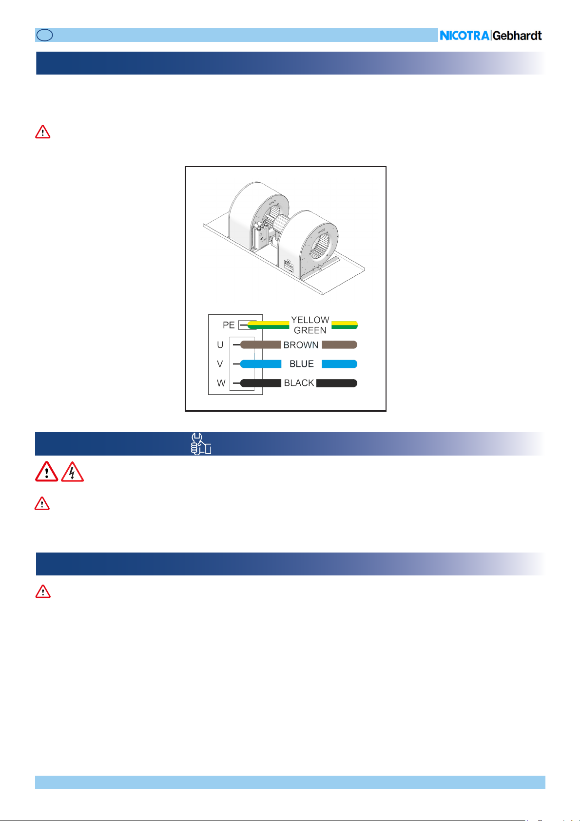
8.2 Motor - driver connections
InthestandardarrangementoftheFDPfan,themotoristurningclockwisewhenseenfromthecable-entryside,andtheelectrical
conneconsofthemotorcabletothedriverboardaremadeasshowninthefollowinggure.
Theactualposionofthemotorconneconsontheprintedcircuitboardmaydier,betweendierentdrivermodels.
These connecons are carried out by Nicotra Gebhardt and cannot be modied by the end user.
WARNINGWARNING
9. INSTALLATION
The fan installaon must be carried out only by competent and qualied sta.
9.1 Commissioning
Work on the device/system by unqualied personnel or failure to comply with warnings can result in severe personal injury or
serious damage to material.
Only suitably qualied personnel trained in the setup, installaon, commissioning and operaon of the product should carry
out work on the device/system.
The FDP fan must be grounded through the PE connector on the driver.
The following terminals can carry dangerous voltages even if the driver is inoperave:
• the power supply terminals L, N or R, S, T
• the motor terminals U, V, W
WARNINGWARNING
In the nal installaon, the device shall be directly connected to the supply terminals and shall have a contact separaon in all
poles, providing full disconnecon under overvoltage category III condions.
WARNINGWARNING
Rev. 0 - 11/12/2020
OPERATING MANUALOPERATING MANUAL
ENEN
16/40
9.2 Operation
Ensure correct grounding connecons. The ground cable must be enough to carry the maximum supply fault current which nor-
mally will be limited by the fuses or MCB. Suitably rated fuses or MCB should be ed in the main supply to the driver, according
to any local legislaon or codes.
WARNINGWARNING
The driver operates at high voltages.
Certain parameter sengs may cause the driver to restart automacally aer an input power failure.
CAUTIONCAUTION
9.3 Ambient operating conditions
The installaon place must be in accordance with the IP protecon degree of the fan. In this respect, refer to the ID plate de-
scribed in chapter 3.
Humidity Range: 90% non-condensing
Altude: if the fan is to be installed at an altude > 1000m, derang is required.
Shocks: do not drop the fan or expose it to sudden shock.
Vibraon: do not install the fan in an area where it is likely to be exposed to constant vibraons.
CAUTIONCAUTION
9.4 Fan installation
Placethefanaccordingtoyourneeds,aerhavingcheckeditsdimensionsandtheposionofthexingholes.
The driver must NOT be removed from the related FDP fan type and size.
The driver cannot be used separate from the related fan.
WARNINGWARNING

Rev. 0 - 11/12/2020
OPERATING MANUALOPERATING MANUAL
ENEN
17/40
9.5 Electrical connections
REF. DESCRIPTION
1Powersupply
2Controlboardconnecon
3Communicaon
4BlinkingLED
5Relayconnecon
21
3
4
FDP 1.05kW 1-Phase
Before carrying out any intervenon on the electrical system, disconnect the power supply by means of main switch.
Make sure that a dierenal switch (circuit breaker) has been installed upstream the line and that it funcons properly.
Work on the driver/fan by unqualied personnel or failure to comply with warnings can result in severe personal injury or serious
damage to material.
Only suitably qualied personnel trained in the set-up, installaon, commissioning and operaon of the product should carry
out work on the driver/fan. This driver must be grounded.
The power supply terminals L, N (1-Phase) and the motor terminals U, V, W can carry dangerous voltages even if the driver is
inoperave.
WARNINGWARNING
Rev. 0 - 11/12/2020
OPERATING MANUALOPERATING MANUAL
ENEN
18/40
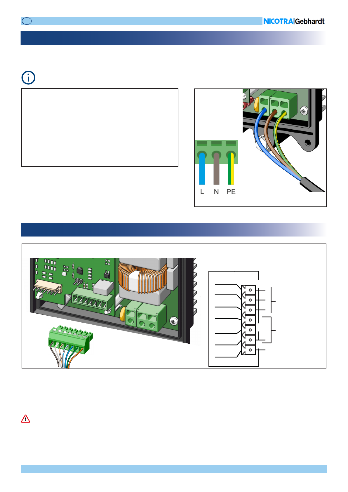
9.5.1 Power supply
Theendusermustconnectthepowersupplycableandthecommandsignaltothecontrolboard,whilethemotorconneconis
alreadydonebyNicotra Gebhardt.
FDP 1.05kW 1-Phase
SinglePhase220/240V±10%@50/60Hz
Theperformancein the range[200V-264V]@ 50Hz/60Hz is
alwaysthesameduetothePFCmoduleinsidethedriver.
Min. and max. wire secon:
Spring-loadedpush-inclamp,suitablefor
• 0.2mm²-24AWGupto2.5mm²-12AWG(stranded)or
4mm²(solid)wire
Useabladedscrewdriver,0.6x3.5mmmax,tounlock.
As concerns the cable minimum secon, check the requirements issued by the country of installaon.
Min. and max. secon:
• 0.13 - 1.31 mm2(26-16AWG)solidorstrandedcable.
9.5.2 Control board connection
FDP 1.05kW 1-Phase
1 GND
2 IN
3 +10V
4 GND
5 B
6 A
7 OUT TACHO
OUT
ANALOGUE
SIGNAL IN
MODBUS
RS485
7 ← 1
Do not reverse the input signal or connect the +10V to signal ground. The driver could be damaged.
Do not apply signals with voltage outside the indicated limits, the driver could be damaged.
WARNINGWARNING

Rev. 0 - 11/12/2020
OPERATING MANUALOPERATING MANUAL
ENEN
19/40
9.5.3 Connection details
Inthisparagraphareexplainedthefeatureandthepossibleconneconofthecontrolboard.
Thecontrolboardterminalsareopto-insulated.
The available features can be dierent depending on the fan model.
9.5.3.1 Analog
ThisisthedriverdefaultmodeandthesignalmustbeconnectedintotheANALOGINPUTandthereferencetoGND.
TheanaloginputcanacceptalsoaPWMsignalwithf>1kHz.
WARNINGWARNING
Do not use devices having the signal GND
connected to the NEUTRAL cable of the
power supply. The driver may be damaged
or not funconing properly.
Theavailable+10Vpowersupplyofthedriver
isintendedtobeusedwithapotenometer
ofminimum 2KOhm, with amaxabsorbed
currentof5mA.
Anydierentdevicesconnectedtoitcould
bringto an undesired functioning ofthe
driverorofconnecteddevice.
Nicotra Gebhardtcan provide a dedicated
potenometer:REGPOTcodeK43138.
Without using the STOP switch Using the STOP switch

Rev. 0 - 11/12/2020
OPERATING MANUALOPERATING MANUAL
ENEN
20/40
Iftwoormorefansareinstalledinthesamecompartmentandoperatedinparallel,thefansmuststartandstopatthesameme.
An auto-restarng alarm occurs when a fan is forced to run forward (or backward) rotaon with a speed higher than
150 rpm.
Ifanext.4-20mAdeviceisused,itisnecessarytoadd0.1%precisionresistancesbetweentheANALOG
INPUT and GND.
Thevalueoftheresistancecanrangefrom:
125Ω->Vsignalrangesfrom0.5Vto2.5V
to500Ω->Vsignalrangesfrom2Vto10V
TACHO / ALARM / FILTER
GND
MODBUS -B
MODBUS -A
GND
TRANSUCER INPUT
ANALOG INPUT
ENABLE
+10V
+24V
Table of contents
Other Nicotra Fan manuals


Popular Fan manuals by other brands

Kendal Lighting
Kendal Lighting AC-24246 installation instructions

Ayce
Ayce FD-40M Original instruction

Martec
Martec Flush AC Series manual

Hunter
Hunter 42660-01 Installation and operation manual

Home Decorators Collection
Home Decorators Collection ALTURA II Use and care guide

Kichler Lighting
Kichler Lighting Kevlar 310150WCP instruction manual


