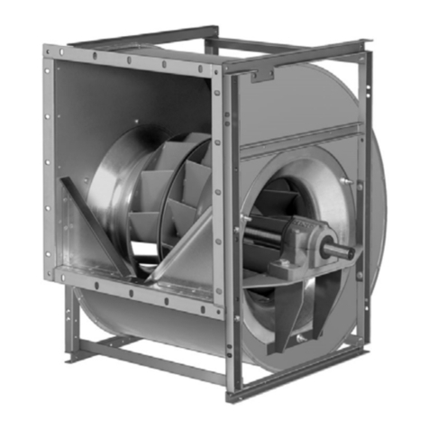
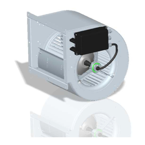
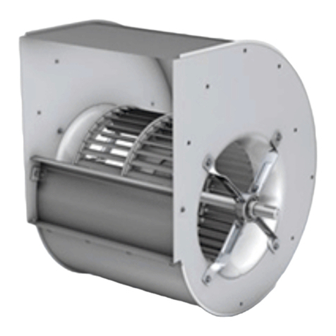
Nicotra RDP User manual

1
Rev. 2 – 1st August 2017
Fan Configuration Program
MANUAL

2
Rev. 2 – 1st August 2017
TABLE OF CONTENTS
1. Description and Requirements ....................................................................................................................... 3
2. Password ....................................................................................................................................................... 3
3. End User License Agreement .......................................................................................................................... 4
4. Select Fan ...................................................................................................................................................... 4
5. Connection .................................................................................................................................................... 6
5.1 USB to RS485 ............................................................................................................................................. 6
5.2 Bluetooth ................................................................................................................................................... 6
5.3 Registers values considerations .................................................................................................................. 8
5.4 Broadcast communication .......................................................................................................................... 8
5.5 Save Comparison........................................................................................................................................ 9
6. Configure ....................................................................................................................................................... 9
7. Performance ................................................................................................................................................ 10
8. Log File ........................................................................................................................................................ 11
9. Save Configuration ....................................................................................................................................... 12
10. Load Configuration ................................................................................................................................... 13
11. Analysis .................................................................................................................................................... 13
12. Revisions .................................................................................................................................................. 14
This software must be used with fans with a firmware Revision 5 or higher

3
Rev. 2 – 1st August 2017
1. Description and Requirements
The Fan Configuration Program is a freeware tool that can be used to check and configure the Nicotra||Gebhardt EC fans
(DDMP, RDP, FDP and PFP) available on the website http://www.nicotra-gebhardt.com/en/.
It runs only on a Windows operating system from XP version onwards with an hard disk available space of 200MB and with
Microsoft Excel installed from 2007 version onwards.
For the connection between the computer and the driver of the fan is necessary an USB to 485 or an USB to 232 converter
(OFFLINE cable, refer to the fan manual for more detail).
After downloading and decompressing the zip file, double click on the setup.exe file and the program will be installed in the
main root of the system C:\Nicotra-Gebhardt
2. Password
At the beginning is required a password to access to different available functionalities.
Some are restricted to the Nicotra||Gebhardt personnel.
Fig.1
For customers two passwords are available:
- CustVIP with all the available functionalities (intended to be used for testing, developing and configuring)
- CustSTD with limited functionalities (intended to be used for monitoring)
With a wrong password inserted the user is anyway able to access to the fan parameters.
In figure 2 are shown the different possible accesses.
Fig.2

4
Rev. 2 – 1st August 2017
3. End User License Agreement
To proceed with any further operations, the user must accept the END USER LICENSE AGREEMENT by clicking here.
Fig. 3
4. Select Fan
The further step is to select the fan type and size (fig.4).
Fig. 4
There are 4 possible choices of fan type: DDMP, RDP, PFP and FDP
Fig. 5

5
Rev. 2 – 1st August 2017
Each fan type has defined range, but for some new product still under evolution.
Fig. 6
For this reason the program can be updated by downloading from the website the latest ZIP update file.
The ZIP file has the date in its description Update_24-02-2017.zip to avoid any possible mistake and must be copied in the
program subdirectory C:\Nicotra-Gebhardt\Updates.
After these operation it is enough to press the Update Product Configuration from the Select Fan page.
After the fan size has been chosen the program allows the user to connect the computer to the fan (Fig. 7).
Fig. 7
An indication of error appears, if there is a mismatch between the fan type chosen and the selected model
Fig. 8

6
Rev. 2 – 1st August 2017
5. Connection
There are two connection mode available: through a USB to RS485 o RS232 converter or through a Bluetooth.
5.1 USB to RS485
The steps for connecting the driver to the PC through the cable are:
- Select the driver slave address (default 1)
- Select the COM Port
- Select the Baud rate
- Select the Stop bits and Parity
- Press the connect Button
Fig. 9
5.2 Bluetooth
This chapter describes the connection between a HC-05 or HC-06 Bluetooth device (refer to the fan manual for the electrical
connections).
To use this connection the Bluetooth peripheral on the computer must be activated.
The HC module runs the SPP (Serial Protocol over Bluetooth) so any device supporting this protocol can be connected to it.
The operation to be ready with the connections are:
- Add a device from the computer Control Panel
The new device should be shown as in figure 10
Fig. 10

7
Rev. 2 – 1st August 2017
- Select the device and press “next” and then enter the pairing code fig. 11 (default = 1234)
Fig. 11
- Wait until the device is ready to be used.
- Check the properties of the device and its virtual COM Port (Fig. 12)
Fig. 12
When the device is correctly installed the operations are:
- Select the Bluetooth Connection
- Search the available devices
- Select the device
- Press the connect button
Fig. 13

8
Rev. 2 – 1st August 2017
5.3 Registers values considerations
Once the connection is established the button in the top left corner becomes green.
And the software will read the Holding Registers values stored inside the fan.
Fig. 14
The stored values are compared with the default values of the selected fan and if they match the color of the registers
changes from Gray to White. When there are some differences the color can be green if the value is anyway allowed or can
be Red if the value shouldn’t be different.
This often occurs when the chosen fan type, fan model or firmware version are wrong (fig. 15)
Fig. 15
Registers in red not necessarily implies a malfunctioning of the fan.
It could be also possible that the software has been correctly updated to the latest version, where the parameters are modified or
improved by Nicotra||Gebhardt and the fan connected belongs to a previous series where the parameters were different.
5.4 Broadcast communication
The broadcast address is 0 and the registers are empty and purple Fig. 15

9
Rev. 2 – 1st August 2017
5.5 Save Comparison
The stored configuration and the compared default values can be saved in an excel file by pressing the folder button, writing
the name without extension and then pressing the save button.
The file will be saved with the name followed by date and time: MyComparisonFile 07-03-2017 16.39.xlsx
In figure 16 is shown an example of the resulting excel file.
Fig. 16
6. Configure
The Configure section gives the possibility to the end user to change all the modifiable parameter of the fan fig. 16.
The most important register is the INPUT TYPE register
Fig. 17
Depending on the fan model, the Input Type register has different possible operating modes and depending on the mode the
related registers are enables or disabled and greyed out.
A red arrow indicates every time which register is active see figure 18
Fig. 18

10
Rev. 2 – 1st August 2017
When an analog mode is selected the red arrow indicated one of the black register in figure 19.
These registers can’t be written and they give the value of the analog signal converted into the related variable.
In figure 19 is shown another selected mode (for a complete explanation of all the possible mode and functioning refer to the
fan manuals).
Fig. 19
7. Performance
The display of the performance is available only for the DDMP.
The display of the Airflow and Pressure values are made by an algorithm inside the software and they are not parameters present inside
the Input Registers of the fan.
Fig. 20
The DDMP driver is able to perform the Constant Airflow regardless of the Fan Configuration Program.

11
Rev. 2 – 1st August 2017
All the Input Registers and the general information/warnings are shown in figure 21 and figure 22.
Fig. 21 Fig. 22
The fan alarms (refer to the fan manual) are indicated in the field below the display
Fig. 23
8. Log File
In this software is available a LOG session where the end user can save the working point of the fan inside its unit.
It is possible to add manually the desired points or start the auto-logging. In this last case the software automatically saves
the working points after a number of seconds indicated in the related field
Fig. 24

12
Rev. 2 – 1st August 2017
When the file is ready to be saved is enough to click on the folder button, write the name of the file without any extension.
Fig. 25
Then press the save button
The Excel will be saved with the data and time: MyLOGfile 07-03-2017 16.39.xlsx
In figure 26 is shown an example of the LOG file.
Fig. 26
9. Save Configuration
All the modification made on the fan configuration can be stored and used for the production line (figure 27).
The modifiable registers are underlined in blue. The configuration can be saved always starting from an existing project.
Fig. 27

13
Rev. 2 – 1st August 2017
If the fan type or size is wrong the access to the saving configuration button will be grayed out.
Fig. 28
10. Load Configuration
The configurations previously saved in the “Save Configuration” page can be found in the “Load Configuration” page.
Fig. 29
Once selected the desired configuration, it can be uploaded into the fan.
A configuration can be deleted by pressing the remove button, but it is possible only for the custom configurations.
11. Analysis
Selecting a PID mode in the Configure page it is possible to access to the PID parameters in the Analysis page and check the
behavior of the fan (for a fast PID tuning explanation refer to the fan manual).
Reference to be expressed in 0.1Volt
PID parameters
Suggestion for the PID parameters
Fig. 30

14
Rev. 2 – 1st August 2017
12. Revisions
Revision 1 -
The firmware revision, the driver model and the fan model are moved from the Connection page to a fixed position.
In this way it is always possible to check these information.
Fig. 31
Revision 2
This revision introduces the possibility to upload the revision of the firmware under the supervision of a NG qualified
technician.
Fig. 32
For this operation two different cables are required:
1) Firmware CABLE For uploading the latest firmware revision
2) Configuration CABLE For configuring the correct parameters
Fig. 33
Both of them must be connected to the computer (USB side) and to the OFFLINE connector of the Driver (232 side).
This operation must be done with the driver POWERED OFF !

15
Rev. 2 – 1st August 2017
1st Operation:
The firmware cable must be connected first.
Fig. 34
2nd Operation:
The firmware uploading program must be launched.
Fig. 35
3rd Operation:
The firmware must be uploaded by a qualified Nicotra||Gebhardt technician through Team Viewer
In figure 36 and 37 there are the screenshots of the tool.
Fig. 36

16
Rev. 2 – 1st August 2017
Fig. 37
4th Operation:
Remove the FIRMWARE cable and insert the CONFIGURATION cable into the OFFLINE connector.
Fig. 38
5th Operation:
Save the custom configuration
Fig. 39

17
Rev. 2 – 1st August 2017
6th Operation:
Configure the driver with the default setting (depending on the size).
Fig. 40
7th Operation:
Load the custom configuration.
Fig. 41

18
Rev. 2 – 1st August 2017
NOTES

19
Rev. 2 – 1st August 2017
NOTES

20
Rev. 2 – 1st August 2017
Table of contents
Other Nicotra Fan manuals
Popular Fan manuals by other brands

Monte Carlo Fan Company
Monte Carlo Fan Company 3DIR58RBD-V1 Owner's guide and installation manual

Hunter
Hunter 23869 Installation and operation manual
Sulion
Sulion MAKI manual
Skov
Skov DA 600 Mounting guide
Vortice
Vortice VORT QUADRO MEDIO I EP AC Instruction booklet

Casablanca
Casablanca CEILING FAN Installation and operation manual

Mitsubishi Electric
Mitsubishi Electric VL-50S2-E operating instructions

Homewerks
Homewerks SmartVent 7146-80-MS instructions
Broan
Broan QTR140L quick start guide
KDK
KDK W56WV Operating and installation instructions
Delta Electronics
Delta Electronics GFB0812DHU Dimensions and installation information
Saturn
Saturn ST-FN8265 quick start guide


