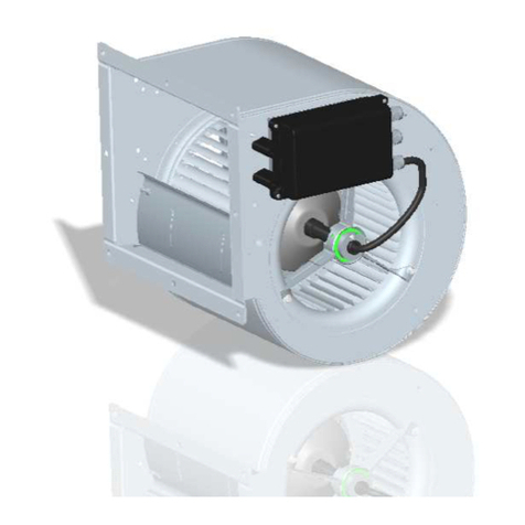
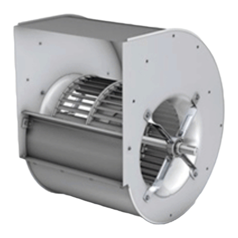
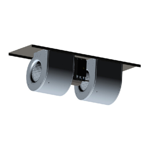
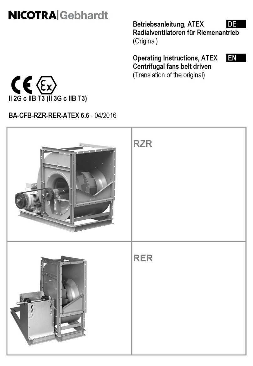
Nicotra RZR Series User manual

Montageanleitung DE
Radialventilatoren für Riemenantrieb
mit Rillenkugellager, Pendelkugellager oder Pendelrollenlager
(Original)
Mountin
g
Instructions EN
Belt Driven Centrifugal Fans
with deep groove ball bearing, self-aligning bearing or swivel-joint
roller bearing
(Translation of the Original)
MA-CFB_BEARING 4.4 – 02/2020
RZR
VZR
TZR
RER

Montageanleitung DE
MA-CFB_BEARING 4.4 – 02/2020 2
Rillenkugellager
a) mit Profilstrebenaufhängung
b) mit Rohrstrebenaufhängung
a) b)
RZR 11-0200/-1000 RZR 11-0200/-0710 IWN
RZR 12-0200/-0710 RZR 12-0200/-0710 IWN
TZR B1-0160/-0710 RZR 19-0200/-0355 (IWN)
TZR B2-0160/-0710
VZR 71-0200/-0560
Hinweise
Die beidseitig abgedichteten, gefetteten Rillenkugellager sind für eine nominelle Lebensdauer (L10h nach DIN ISO 281-1) von
20.000 bzw. 40.000 Betriebsstunden ausgelegt. Die Wartung erfolgt gemäß der Betriebsanleitung RZR / RER, Kapitel
Instandhaltung / Wartung. Sollte ein Lagerwechsel erforderlich werden, sind die Sicherheitsvorschriften der
Betriebsanleitung RZR / RER zwingend einzuhalten!
Allgemeines
Um die Ventilatorlagerungen zugänglich zu machen, sind unter Einhaltung der Sicherheits- und Unfallverhütungsvorschriften
und der örtlichen und baulichen Gegebenheiten div. Demontagearbeiten auszuführen (z.B. Netztrennung, Riementrieb,
Schutz- und Überwachungseinrichtungen, Kanäle).
Lager-Demontage
1. Stiftschraube (1) lösen, Exzenterspannring (2) entgegen der Laufraddrehrichtung lösen und abnehmen.
2. Laufrad oder Welle unterbauen und sichern
3. a) Profilstrebenaufhängung (3) demontieren, Gummidämmring abnehmen und Lager mit geeignetem Werkzeug am
Innenring abziehen (Ein Anwärmen der Lager auf 200°C erleichtert die Demontage wesentlich jedoch nicht unbedingt
erforderlich).
3. b) Lagerstreben-Befestigung am Gehäuse lösen und komplette Lageraufhängung und Lager mit geeignetem Werkzeug
abziehen. (Ein Anwärmen der Lager auf 200°C erleichtert die Demontage wesentlich jedoch nicht unbedingt
erforderlich).
Lager-Montage
1. Lagersitz auf der Welle und Lager-Innenring gründlich säubern und mit Fettlösungsmittel (Waschbenzin o.ä.) entfetten.
2. Vormontierte Trageinheit (Tragstern und Lager) auf die Welle schieben und am Gehäuse befestigen. Lagersitz mit Kleber
beträufeln.
3. Luftspalt zwischen Lüfterrad und Einströmdüse einstellen.
4. Nach dem Einstellen nochmals Kleber zwischen Lagerinnenring und Welle, wie in der Skizze dargestellt, aufträufeln.
5. Exzenterspannring (2) auf die Welle schieben und mit dem Lager in Drehrichtung des Laufrades mit leichtem Prellschlag
verspannen, Stiftschraube (1) anziehen. Die Aushärtung des Klebers ist temperaturabhängig sie beträgt bei +20°C ca. 24h.
Metall
Kleber
1
2
3
nur bei
IWN...
a)
Metall
Kleber
b)
2
1

Montageanleitung DE
MA-CFB_BEARING 4.4 – 02/2020 3
Pendellager
mit Gussgehäuse und Rohrstrebenaufhängung
RZR 15-0400/-1000
RZR 19-0400/-1000
TZR B5-0400/-1000
(Seite 1 von 2)
Hinweise
Die eingebauten Pendellager, befestigt mittels Spannhülse, sind für eine nominelle Lebensdauer (L10h nach DIN ISO 281-1)
von 20.000 bzw. 40.000 Betriebsstunden ausgelegt. Die Wartung erfolgt gemäß der Betriebsanleitung RZR / RER, Kapitel
Instandhaltung / Wartung. Sollte ein Lagerwechsel erforderlich werden, sind die Sicherheitsvorschriften der
Betriebsanleitung RZR / RER zwingend einzuhalten!
Allgemeines
Um die Ventilatorlagerungen zugänglich zu machen, sind unter Einhaltung der Sicherheits- und Unfallverhütungsvorschriften
und der örtlichen und baulichen Gegebenheiten div. Demontage-Arbeiten auszuführen (z.B. Netztrennung, Riementrieb,
Schutz- und Überwachungs-Einrichtungen, Kanäle).
Lager-Demontage
1. Lagerdeckel-Befestigungsschrauben (3) lösen und Lagerdeckel (4) abnehmen
2. Sicherungsblech der Hülsenmutter aufbiegen und Hülsenmutter (6) soweit lösen (ca. 2-3 Umdrehungen), bis die Stirnfläche
mit der Spannhülse bündig ist
3. Schlagkappe oder Rohrstück gegen die Hülsenmutter ansetzen und mit Prellschlägen Spannhülse zurückschlagen
(lockern)
4. Laufrad oder Welle unterbauen und sichern
5. Schrauben der Tragsternbefestigung vom Ventilatorgehäuse lösen und Tragstern abnehmen.
Das Lager kann nun ausgewechselt werden.
A-Lager
(
Antriebsseite
)
B-Lager
10 11

Montageanleitung DE
MA-CFB_BEARING 4.4 – 02/2020 4
Pendellager
mit Gussgehäuse und Rohrstrebenaufhängung
RZR 15-0400/-1000
RZR 19-0400/-1000
TZR B5-0400/-1000
(Seite 2 von 2)
Lager-Montage
Die Montage der Lager erfolgt sinngemäß in umgekehrter Reihenfolge, dabei ist auf absolute Sauberkeit der Komponenten
zu achten.
- Überdeckung von Einlassring und Laufrad vermitteln
- Neufettung der Lager siehe nachfolgender Abschnitt
1. Die Lager werden so montiert, dass eine schwimmende Anordnung entsteht.
2. Das B-Lager liegt mit der Schulter des Außenrings an dem inneren Gehäusebund bei (8) an.
3. Dem A-Lager wird eine Federscheibe (9) beigelegt, die einen Federweg von ~3mm ausführen kann.
4. A-Lager bündig mit dem Lagergehäuse ausrichten (10). Beim Festziehen schiebt sich das Lager ca. 0,4mm nach innen
(11). Mit dem Gehäusedeckel wird das Lager um ca. weitere 1,5mm nach innen in das Lagergehäuse geschoben.
5. Bei der Befestigung der Lager auf der Welle erfolgt gleichzeitig das Einstellen des Lagerspiels. Damit eine hohe
Lagerlebensdauer erreicht wird, ist hierbei eine besondere Sorgfalt erforderlich!
Zur Vermeidung von Lagervorschädigungen Folgendes beachten:
Keine Schläge bei der Lagermontage anwenden!
Die Anzugmethoden der versch. Hersteller dürfen nicht vertauscht werden!
Das Anziehen der Hülsenmutter erfolgt in zwei Schritten:
-1. Schritt: Die Hülsenmutter wird soweit gleichmäßig angezogen, bis die Welle, die Hülse und der Lager-Innenring
möglichst „satt“ (formschlüssig) aneinander liegen (sog. „Festpunkt“ suchen).
Bei FAG-Lagern wird dies erreicht, indem die Hülsenmutter mit einem definierten Drehmoment angezogen wird. Dazu ist
allerdings ein spezielles Werkzeug von FAG erforderlich. Bei Verwendung von „Standard-Werkzeug“ gelten andere Anzug-
momente als für das Original-FAG-Werkzeug! (Unterscheidung in Tabelle 1 beachten!)
-2. Schritt: Je nach Ventilator- bzw. Lagergröße wird die Hülsenmutter wie in Tabelle 1 angegebenen, angezogen. Da sich
bei diesem Vorgang die notwendige Lagerluft ergibt, muss dieser Vorgang mit Sorgfalt erfolgen.
Es müssen die für den jeweiligen Lagerhersteller angegebenen Verfahren und Anzugwerte beachtet werden. Ein
vertauschen ist nicht zulässig!
Zum Anziehen der Hülsenmutter darf nur zulässiges Werkzeug verwendet werden (z.B. Hakenschlüssel,
Hydraulikmutter). Das Festziehen der Hülsenmutter mit Dorn oder Meißel und Hammer ist nicht zulässig!
6. Hülsenmutter sichern (eine Lasche des Sicherungsblechs umbiegen)
Achtung!
Hülsenmutter niemals zum sichern zurückdrehen! Stets in Befestigungsrichtung weiterdrehen, bis sich eine Lasche
in eine der Nuten umbiegen lässt.
Befettung
Die Befettung ist mit dem jeweils vorgeschriebenen Qualitätsfett vorzunehmen (siehe auch Betriebsanleitung RZR).
- Hohlräume des Pendelkugellagers selbst vollständig mit Fett füllen
- Lagergehäuse zur Hälfte (50%) mit Fett befüllen.
Tabelle 1
Ventilatoren
RZR ..- Lager Typ
Lagerluft C3 -
vor Einbau
[µm]
SKF-
Lager
SNR- und
Rollway-
Lager
FAG-Lager
1.Schritt:
A
nzugmoment
2.Schritt
Winkel
min. max.
Anzugs-
winkel
Anzug-
winkel
mit FAG-
Werkzeug
mit Standard-
Drehmoment-
schlüssel
+ Anzug-
winkel
0400 / 0450 / 0500 2307 K/C3 + H 2307
Pendel-
kugel-
lager
29 46 70° 80° 35 Nm 38 Nm + 66°
0560 / 0630 2309 K/C3 + H 2309 33 52 70° 80° 58 Nm 61 Nm + 72°
0710 / 0800 2311 K/C3 + H 2311 41 61 75° 100° 93 Nm 100 Nm + 66°
0900 / 1000 2313 K/C3 + H 2313 50 75 80° 100° 97Nm 107 Nm + 80°
TZR B5-
0400 / 0450 / 0500 2307 K/C3 + H 2307
Pendel-
kugel-
lager
29 46 70° 80° 35 Nm 38 Nm + 66°
0560 / 0630 2309 K/C3 + H 2309 33 52 70° 80° 58 Nm 61 Nm + 72°
0710 / 0800 2311 K/C3 + H 2311 41 61 75° 100° 93 Nm 100 Nm + 66°
0900 / 1000 2313 K/C3 + H 2313 50 75 80° 100° 97Nm 107 Nm + 80°
Bei Montage neuer Lagerkomponenten die Beipackanleitung beachten, ggf. die Anweisungen und Werte des
jeweiligen Herstellers beachten!

Montageanleitung DE
MA-CFB_BEARING 4.4 – 02/2020 5
Pendellager
mit Spannhülse und Steh-Gussgehäuse
RZR 13-0400/-1600 (IWN)
RER 13-0200/-1600 (IWN)
RER 17-0200/-1000 (IWN)
(Seite 1 von 3)
Hinweise
Die eingebauten Pendellager mit Spannhülse sind für eine nominelle Lebensdauer (L10h nach DIN ISO 281-1) von 20.000 bzw.
40.000 Betriebsstunden ausgelegt. Die Wartung erfolgt gemäß der Betriebsanleitung RZR / RER, Kapitel Instandhaltung /
Wartung. Sollte ein Lagerwechsel erforderlich werden, sind die Sicherheitsvorschriften der Betriebsanleitung RZR /
RER zwingend einzuhalten!
Allgemeines
Um die Ventilatorlagerungen zugänglich zu machen, sind unter Einhaltung der Sicherheits- und Unfallverhütungsvorschriften
und der örtlichen und baulichen Gegebenheiten div. Demontage-Arbeiten auszuführen (z.B. Netztrennung, Riementrieb,
Schutz- und Überwachungs-Einrichtungen, Kanäle).
Lager-Demontage
1. Lagergehäusedeckel (1) demontieren
2. Sicherungsblech der Hülsenmutter (2) aufbiegen und Hülsenmutter soweit lösen (ca. 2-3 Umdrehungen), dass die
Stirnfläche mit der Spannhülse bündig ist.
3. Schlagkappe oder Rohrstück gegen die Hülsenmutter ansetzen und mit Prellschlägen die Spannhülse zurück schlagen. Bei
axial und radial entlasteten Lagern kann auch der Innenring von der Spannhülse geschlagen werden.
4. Befestigungsschrauben am Lagergehäuse-Unterteil lösen
5. Laufrad oder Welle unterbauen und sichern
6. Lagergehäuse-Unterteil mit Lager von der Welle abnehmen.
Lager-Montage
Die Montage der Lager erfolgt sinngemäß in umgekehrter Reihenfolge, dabei ist auf absolute Sauberkeit der Komponenten
zu achten - Überdeckung von Einlassring und Laufrad vermitteln
Achtung!
Ober- und Untererteile der Stehgussgehäuse nicht untereinander vertauschen und nicht verdrehen!
Ober- und Unterschale vor der Demontage markieren.
1. Eines der Lager durch einsetzen von 2 Festringen zum Festlager machen, vorzugsweise auf der Antriebsseite.
Achtung!
Auf der Loslagerseite keine Festringe einlegen!
2. Bei der Befestigung der Lager auf der Welle erfolgt gleichzeitig das Einstellen des Lagerspiels. Damit eine hohe
Lagerlebensdauer erreicht wird, ist hierbei eine besondere Sorgfalt erforderlich!
Zur Vermeidung von Lagervorschädigungen Folgendes beachten:
Keine Schläge bei der Lagermontage anwenden!
Die Anzugmethoden der versch. Hersteller dürfen nicht vertauscht werden!
Das Anziehen der Hülsenmutter erfolgt in zwei Schritten:
-1. Schritt: Die Hülsenmutter wird soweit gleichmäßig angezogen, bis die Welle, die Hülse und der Lager-Innenring
möglichst „satt“ (formschlüssig) aneinander liegen (sog. „Festpunkt“ suchen).
Bei FAG-Lagern wird dies erreicht, indem die Hülsenmutter mit einem definierten Drehmoment angezogen wird. Dazu ist
ein spezielles Werkzeug von FAG erforderlich. Bei Verwendung von „Standard-Werkzeug“ gelten andere Anzugmomente
als für das Original-FAG-Werkzeug! (Unterscheidung in Tabelle 2+3 beachten!)
-2. Schritt: Je nach Ventilator- bzw. Lagergröße wird die Hülsenmutter wie in Tabelle 2+3 angegebenen, angezogen. Da
sich bei diesem Vorgang die notwendige Lagerluft ergibt, muss dieser Vorgang mit Sorgfalt erfolgen.
Es müssen die für den jeweiligen Lagerhersteller angegebenen Verfahren und Anzugwerte beachtet werden. Ein
vertauschen ist nicht zulässig!
Zum Anziehen der Hülsenmutter darf nur zulässiges Werkzeug verwendet werden (z.B. Hakenschlüssel,
Hydraulikmutter, ...). Das Festziehen der Hülsenmutter mit Dorn oder Meißel und Hammer ist nicht zulässig!
3. Hülsenmutter sichern (eine Lasche des Sicherungsblechs umbiegen)
Achtung!
Hülsenmutter niemals zum sichern zurückdrehen! Stets in Befestigungsrichtung weiterdrehen, bis sich die nächste
Lasche in eine der Nuten umbiegen lässt.
4. Verbindungsschrauben des Gehäuseober- und Unterteils mit dem in Tab. 2+3 angegebenen Drehmoment anziehen.
Befettung
Die Befettung ist mit dem jeweils vorgeschriebenen Qualitätsfett vorzunehmen (siehe auch Betriebsanleitung RZR / RER).
- Hohlräume des Pendelkugellagers selbst vollständig mit Fett füllen
- Lagergehäuse zur Hälfte (50%) mit Fett befüllen.
Standard und IWN
1
2
2
nur bei IWN...
2
Lagerausrichtung RZR Lagerausrichtung RER 13/17
2

Montageanleitung DE
MA-CFB_BEARING 4.4 – 02/2020 6
Pendellager
mit Spannhülse und Steh-Gussgehäuse
RZR 13-0400/-1600 (IWN)
RER 13-0200/-1600 (IWN)
RER 17-0200/-1000 (IWN)
(Seite 2 von 3)
Tabelle 2 (nur für RZR)
Ventilator-
Baugröße
La
g
er-Bauart
Lagerluft
C3 vor
Einbau
[µm]
Radialluftvermin-
der-un
g
in mm
Anzugmoment
Verbind-ungs-
schauben Stehguss-
Gehäuse
SKF-
Lager
SNR-
Lager
FAG- Lager
1. Schritt:
Anzugmoment
2. Schritt:
Winkel
Lager Typ min. max.
Lagergehäuse Typ
Anzug-
winkel
Anzug-
winkel
mit FAG-
Werkzeug
mit Standard-
Drehmoment-
werkzeug
+ Anzug-
winkel
RZR 0400
RZR 0450
RZR 0500
2307 K/C3
+ H 2307
Pendel
–
Ku
g
el - La
g
er
29 46
SKF SNL 508-607 TG
SNR SNC 508-607
FAG SNV 080-L
=> 50Nm / M10
=> 65Nm / M12
=> 36Nm / M10
70° 80° 35 Nm 38 Nm + 66°
RZR 0560
RZR 0630
2309 K/C3
+ H 2309 33 52
SKF SNL 511-609 TG
SNR SNC 511-609
FAG SNV 100-L
=> 80Nm / M12
=>150Nm / M16
=> 61Nm / M12
70° 80° 58 Nm 61 Nm + 72°
RZR 0710
RZR 0800
2311 K/C3
+ H 2311 41 61
SKF SNL 513-611 TG
SNR SNC 513-611
FAG SNV 120-L
=> 80Nm / M12
=>150Nm / M16
=> 61Nm / M12
75° 100° 93 Nm 100 Nm + 66°
RZR 0900
RZR 1000
2313 K/C3
+ H 2313 50 75
SKF SNL 516-613 TG
SNR SNC 516-613
FAG SNV 140-L
=> 80Nm / M12
=>290Nm / M20
=> 61Nm / M12
80° 100° 97 Nm 107 Nm + 80°
RZR 1120 22216 EK/C3
+H316
Pendel
–
Rollen - La
g
er
95 120
0,03
bis
0,04
SKF SNL 516-613 TG
SNR SNC 516-613
FAG SNV 140-L
=> 80Nm / M12
=>290Nm / M20
=> 61Nm / M12
130°
Kontroll-
wert: 0,04
Anziehen der Hülsenmutter entsprechend der
Spalte „Radialluftverminderung“;
Restspiel: 0,045-0,08
Kontrollwert für kleinstes Radialspiel: 0,04mm
RZR 1250 22218 EK/C3
+H318 110 140
0,04
bis
0,05
SKF SNL 518-615 TG
SNR SNC 518-615
FAG SNV 160-L
=>150Nm / M16
=>290Nm / M20
=>150Nm / M16
150°
Kontroll-
wert: 0,05
Anziehen der Hülsenmutter entsprechend der
Spalte „Radialluftverminderung“;
Restspiel: 0,05 … 0,095
Kontrollwert für kleinstes
Radialspiel: 0,05mm
RZR 1400
RZR 1600
22220 EK/C3
+H320 110 140
0,045
bis
0,06
SKF SNL 520-617 TG
SNR SNC 520-617
FAG SNV 180-L
=>200Nm / M20
=>500Nm / M24
=>301Nm / M20
150°
Kontroll-
wert: 0,05
Bei Montage neuer Lagerkomponenten die Beipackanleitung beachten, ggf. die Anweisungen und Werte des
jeweiligen Herstellers beachten!
Achtung!
Weil sich die Bauart des FAG- und des
„Standard“-Drehmomentschlüssels
unterscheidet, sind beim Schritt 1 der
Lagerbefestigung die korrekten
Momentenwerte zu verwenden!
Eine Vertauschung ist nicht erlaubt.
Beim FAG-Werkzeug ist das Zentrum der
Hülsenmutter und der Drehpunkt des
Auslösemechanismus nicht deckungsgleich.
Dadurch ergeben sich für die beiden
Drehmomentschlüssel unterschiedliche
Hebelverhältnisse und damit Einstellwerte!
qq
Drehpunkt der Drehpunkt / Knickpunkt
Hülsenmutter des FAG-Drehmomentschlüssels

Montageanleitung DE
MA-CFB_BEARING 4.4 – 02/2020 7
Pendellager
mit Spannhülse und Steh-Gussgehäuse
RZR 13-0400/-1600 (IWN)
RER 13-0200/-1600 (IWN)
RER 17-0200/-1000 (IWN)
(Seite 3 von 3)
Tabelle 3 (nur für RER)
Ventilator-
Baugröße
La
g
er-Bauart
Lagerluft
C3 vor
Einbau
[µm]
Radialluftvermin-
de
r-
u
n
g
in mm
Anzugmoment
Verbindungs-
schauben Stehguss-
Gehäuse
SKF-
Lager
SNR-
Lager
FAG- Lager
1. Schritt:
Anzugmoment
2. Schritt:
Winkel
Lager Typ min. max. Lagergehäuse Typ
Anzug-
winkel
Anzug-
winkel
mit FAG-
Werkzeug
mit Standard-
Drehmoment-
werkzeug
Anzug-
winkel
RER 0200
RER 0225
RER 0250
2306 K/C3
+ H2306
Pendel
–
Ku
g
el - La
g
er
23 39
SKF SNL 507-606 TG
SNR SNC 507-606
FAG SNV 72-L
=> 50Nm / M10
=> 65Nm / M12
=> 36Nm / M10
55° 80° 35 Nm 37 Nm + 54°
RER 0280
RER 0315
RER 0355
RER 0400
RER 0450
RER 0500
2307 K/C3
+ H 2307 29 46
SKF SNL 508-607 TG
SNR SNC 508-607
FAG SNV 080-L
=> 50Nm / M10
=> 65Nm / M12
=> 36Nm / M10
70° 80° 35 Nm 38 Nm + 66°
RER 0560
RER 0630
RER 0710
2309 K/C3
+ H 2309 33 52
SKF SNL 511-609 TG
SNR SNC 511-609
FAG SNV 100-L
=> 80Nm / M12
=>150Nm / M16
=> 61Nm / M12
80° 80° 58 Nm 61 Nm + 72°
RER 0800
RER 0900
RER 1000
2311 K/C3
+ H 2311 41 61
SKF SNL 513-611 TG
SNR SNC 513-611
FAG SNV 120-L
=> 80Nm / M12
=>150Nm / M16
=> 61Nm / M12
75° 100° 93 Nm 100 Nm + 66°
RER 1120 22213 CCK/C3
+H2313
Pendel
–
Rollen - La
g
er
75 95
0,03
bis
0,04
SKF SNL 516-613 TG
SNR SNC 516-613
FAG SNV 140-L
=> 80Nm / M12
=>290Nm / M20
=> 61Nm / M12
110°
Kontroll-
wert: 0,04
Anziehen der Hülsenmutter entsprechend der
Spalte „Radialluftverminderung“;
Restspiel: 0,035 … 0,065
Kontrollwert für kleinstes Radialspiel: 0,035mm
RER 1250 22216 CCK/C3
+H316 95 120
0,04
bis
0,05
SKF SNL 516-613 TG
SNR SNC 516-613
FAG SNV 140-L
=> 80Nm / M12
=>290Nm / M20
=> 61Nm / M12
130°
Kontroll-
wert: 0,04
Anziehen der Hülsenmutter entsprechend der
Spalte „Radialluftverminderung“;
Restspiel: 0,045-0,08
Kontrollwert für kleinstes Radialspiel: 0,04mm
RER 1400
RER 1600
22218 EK/C3
+H318 110 140
0,045
bis
0,06
SKF SNL 518-615 TG
SNR SNC 518-615
FAG SNV 160-L
=>150Nm / M16
=>290Nm / M20
=>150Nm / M16
150°
Kontroll-
wert: 0,05
Anziehen der Hülsenmutter entsprechend der
Spalte „Radialluftverminderung“;
Restspiel: 0,05 … 0,095
Kontrollwert für kleinstes Radialspiel: 0,05mm
Bei Montage neuer Lagerkomponenten die Beipackanleitung beachten, ggf. die Anweisungen und Werte des
jeweiligen Herstellers beachten!
Achtung!
Weil sich die Bauart des FAG- und des
„Standard“-Drehmomentschlüssels
unterscheidet, sind beim Schritt 1 der
Lagerbefestigung die korrekten
Momentenwerte zu verwenden!
Eine Vertauschung ist nicht erlaubt.
Beim FAG-Werkzeug ist das Zentrum der
Hülsenmutter und der Drehpunkt des
Auslösemechanismus nicht deckungsgleich.
Dadurch ergeben sich für die beiden
Drehmomentschlüssel unterschiedliche
Hebelverhältnisse und damit Einstellwerte!
qq
Drehpunkt der Drehpunkt / Knickpunkt
Hülsenmutter des FAG-Drehmomentschlüssels

Montageanleitung DE
MA-CFB_BEARING 4.4 – 02/2020 8
Rillenkugellager
mit Blechflansch-Blechstrebenbefestigung
RER 11-0200/-0710
RER 12-0200/-0710
RER 15-0400/-0710
(Seite 1 von 1)
Hinweise
Die beidseitig abgedichteten, gefetteten Rillenkugellager sind für eine nominelle Lebensdauer (L10h nach DIN ISO 281-1) von
20.000 bzw. 40.000 Betriebsstunden ausgelegt. Sollte ein Lagerwechsel erforderlich werden, sind die
Sicherheitsvorschriften der Betriebsanleitung RZR / RER zwingend einzuhalten!
Allgemeines
Um die Ventilatorlagerungen zugänglich zu machen, sind unter Einhaltung der Sicherheits- und Unfallverhütungsvorschriften
und der örtlichen und baulichen Gegebenheiten div. Demontage-Arbeiten auszuführen (z.B. Netztrennung, Riementrieb,
Schutz- und Überwachungs-Einrichtungen, Kanäle).
0200/-0355
0400/-1000
Lager-Demontage
1. Stiftschrauben (1) lösen, Excenter-Spannringe (2) entgegen der Laufraddrehrichtung lösen und abnehmen.
Lager-saugseitig (0200/-1000)
2. Profilstrebenaufhängung (3) demontieren.
3. Gummidämmring abnehmen und Lager mit geeignetem Werkzeug am Innenring abziehen (Ein Anwärmen der Lager auf
200°C erleichtert die Demontage wesentlich jedoch nicht unbedingt erforderlich).
Lager-antriebseitig (0200/-0355)
4. Flanschgehäuse(4) demontieren, Gummidämmring abnehmen und Lager abziehen
Lager-antriebseitig (0400/-1000)
5. Muttern von Schrauben (5) lösen. 2 Schrauben M10×30 in die freien Gewindebohrungen M10 im Gehäuse einschrauben,
damit das Gehäuse abdrücken, dass ein Dreiarm-Abzieher angesetzt werden kann. Abzieher am
Gussgehäuse (6) ansetzen und Gussgehäuse mit Lager abziehen.
Lager-Montage
1. Lagersitz auf der Welle und Lager-Innenring gründlich reinigen und mit Fettlösungsmittel (Waschbenzin o.ä.) entfetten.
2. Vormontierte Trageinheit auf die Welle schieben und am Gehäuse befestigen. Lagersitz mit Kleber beträufeln.
3. Luftspalt zwischen Lüfterrad und Einströmdüse einstellen.
Nach dem Einstellen nochmals Kleber zwischen Lager-Innenring und Welle, wie in der Skizze dargestellt, aufträufeln.
4. Excenter-Spannring (2) auf die Welle schieben und mit dem Lager in Drehrichtung des Laufrades mit leichtem Prellschlag
verspannen, Stiftschraube (1) anziehen. Die Aushärtung des Klebers ist temperaturabhängig sie beträgt bei +20°C ca.
24h.
Nicotra Gebhardt GmbH
Gebhardtstraße 19-25
74638 Waldenburg, Germany
Telefon +49 (0)7942 1010
Telefax +49 (0)7942 101170
www.nicotra-
g
ebhardt.com
1
2 2
3
3 4 5
6
1
Metall
Kleber
Metall
Kleber

Mounting Instructions EN
Belt Driven Centrifugal Fans
with deep groove ball bearing, self-aligning bearing or swivel-joint
roller bearing
(Translation of the Original)
MA-CFB_BEARING 4.4 – 02/2020
RZR
VZR
TZR
RER

Mounting Instructions EN
MA-CFB_BEARING 4.4 – 02/2020 2
Deep groove ball bearing
a) with profile strut support
b) with tubular strut support
a) b)
RZR 11-0200/-1000 RZR 11-0200/-0710 IWN
RZR 12-0200/-0710 RZR 12-0200/-0710 IWN
TZR B1-0160/-0710 RZR 19-0200/-0355 (IWN)
TZR B2-0160/-0710
VZR 71-0200/-0560
Notes
The greased deep groove ball bearings sealed on both sides are designed for a nominal service life (L10h according to DIN ISO
281-1) of 20,000 respectively 40,000 operating hours. Maintenance must be carried out according to the chapter on
upkeep/maintenance in the RZR / RER operating instructions. If it is required to change the bearings, the safety
instructions stipulated in the RZR / RER operating instructions must be followed without fail!
General information
To expose the fan bearings, various dismounting work (e.g. disconnection from the mains, belt drive, protective and
monitoring devices, ducts), must be performed in compliance with the safety and accident protection regulations and the local
and structural conditions.
Dismounting the bearing
1. Unscrew the locking screw (1), unscrew the eccentric clamping ring (2) against the direction of rotation of the running wheel
and remove it.
2. Prop and secure running wheel or shaft
3. a) Dismount profile strut support (3), Remove rubber insulating ring and pull the bearing off the inner ring with a suitable
tool (Warming the bearings up to 200°C facilitates dismounting substantially, is however not necessarily required).
3. b) Loosen the bearing pipe fastening on the housing and pull off the complete bearing support and bearing with a
suitable tool. (Warming the bearings up to 200°C facilitates dismounting substantially, is however not necessarily
required).
Mounting the bearing
1. Clean the seat of the roller bearing on the shaft and the inner ring of the bearing thoroughly and remove the grease from
them with fat dissolving agents (petroleum benzine, etc.).
2. Push pre-assembled supporting unit (star-shaped support and bearing) on the shaft and fasten it to the housing. Apply
drops of adhesive to the seat of the bearing.
3. Adjust the air gap between the fan wheel and the inlet nozzle.
4. After adjustment apply drops of adhesive between the inner ring of the bearing and the shaft as shown in the drawing.
5. Push the eccentric clamping ring (2) on the shaft and tighten it with the bearing in the direction of rotation of the running
wheel with a light jarring blow, tighten the locking screw (1). The hardening time of the adhesive depends on the
temperature, it takes approx. 24 h at +20°C.
metal
adhesive
1
2
3
only for
IWN...
a)
b)
2
1

Mounting Instructions EN
MA-CFB_BEARING 4.4 – 02/2020 3
Self-aligning bearing
with cast housing and tubular strut support
RZR 15-0400/-1000 (IWN)
RZR 19-0400/-1000 (IWN)
TZR B5-0400/-1000 (IWN)
(Page 1 of 2)
Notes
The built-in self-aligning bearings with clamping sleeve are designed for a nominal service life (L10h according to DIN ISO 281-
1) of 20,000 respectively 40,000 operating hours. Maintenance must be carried out according to the chapter on
upkeep/maintenance in the RZR / RER operating instructions. If it is required to change the bearings, the safety
instructions stipulated in the RZR / RER operating instructions must be followed without fail!
General info
To expose the fan bearings, various dismounting work (e.g. disconnection from the mains, belt drive, protective and
monitoring devices, ducts), must be performed in compliance with the safety and accident protection regulations and the local
and structural conditions.
Dismounting the bearing
1. Unscrew the bearing cover fastening screws (3) and remove the bearing cover (4)
2. Bend up the safety plate of the sleeve nut and loosen the sleeve nut (6) (approx. 2-3 rotations) until the front face is flush
with the clamping sleeve
3. Set blow cap or pipe section against the sleeve nut and loosen the clamping sleeve with jarring blows
4. Prop and secure running wheel or shaft
5. Unscrew the star-shaped support fastening off the fan housing and remove star-shaped support.
Now the bearing can be replaced.
A-Bearing
(
drive side
)
B-Bearin
g
Spring washer
(only drive site)
10 11

Mounting Instructions EN
MA-CFB_BEARING 4.4 – 02/2020 4
Self-aligning bearing
with cast housing and tubular strut support
RZR 15-0400/-1000 (IWN)
RZR 19-0400/-1000 (IWN)
TZR B5-0400/-1000 (IWN)
(Page 2 of 2)
Mounting the bearing
The bearings are accordingly mounted in the reverse order, it must be ensured that the components are absolutely clean.
- Centre the covering of the inlet ring and running wheel
- For re-greasing the bearings see following section
1. The bearings are mounted so that a floating layout is created.
2. The B-bearing abuts the inner collar of the housing at (8) with the shoulder of the outer ring.
3. To the A-bearing is a spring washer (9) attached that can execute a spring range of ~3mm.
4. The A-bearing should line up precisely with the bearing housing (10). When tightening, the bearing moves about 0,4mm
towards inside (11). With the housing cover, the bearing is pushed further by around 1,5mm inwards into the bearing
housing.
5. The bearing clearance must be set at the same time that the bearing is fastened to the shaft. To ensure that the bearing
lifespan is long, special care must be taken here!
In order to avoid premature damage, please note the following:
Do not subject the bearing mounting to knocks and blows!
The tightening methods of the different manufacturers must not be interchanged!
Tighten the sleeve nut as per the following two steps:
-Step 1: The sleeve nut must be evenly tightened until the shaft, the sleeve and the inner ring of the bearing are as close
together as possible (interlocking) (look for the so-called "fixed point").
For FAG bearings this point is reached when the sleeve nut is tightened with a defined torque. To do this, you will however
need the special tool supplied by FAG. When using the “standard tool” other tightening torques than those for the original
FAG tool apply! (Note the differences in Table 1!)
-Step 2: Depending on the fan or the bearing size, the sleeve nut is tightened as stated in Table 1. As this process results in
the necessary bearing clearance, this process must be undertaken with care.
The procedures and tightening values must be observed as given by the bearing manufacturer. It is not permitted to
exchange one process for the other!
Only the approved tools must be used to tighten the locknut, e.g. hook spanner, hydraulic nut, etc. It is not permitted to
tighten the locknut with a mandrel or hammer and chisel!
6. Secure the sleeve nut (bend back a tab of the safety plate)
Caution!
Never turn sleeve nuts back to secure them! Always continue to turn them in the tightening direction until a tab of
one the nuts can be bent backwards.
Lubrication
Lubrication must always be undertaken with the recommended quality lubricant (see the RZR Operating Instructions).
- Fill the hollows of the self-aligning bearings completely with lubricant.
- Fill the bearing housing half (50%) with lubricant.
Table 1
Fan
RZR ..- Bearing Type
Bearing
clearance C3 -
Before
mounting [µm]
SKF-
bearing
SNR- and
Rollway-
bearing
FAG bearings
Step 1:
Tightening torque
Step 2:
Angle
min. max.
Tightening
angle
Tightening
angle
FAG
tool
Torque
tool
+ Tightening
angle
0400 / 0450 / 0500 2307 K/C3 + H 2307
Self-
aligning
bearing
29 46 70° 80° 35 Nm 38 Nm + 66°
0560 / 0630 2309 K/C3 + H 2309 33 52 70° 80° 58 Nm 61 Nm + 72°
0710 / 0800 2311 K/C3 + H 2311 41 61 75° 100° 93 Nm 100 Nm + 66°
0900 / 1000 2313 K/C3 + H 2313 50 75 80° 100° 97Nm 107 Nm + 80°
TZR B5-
0400 / 0450 / 0500 2307 K/C3 + H 2307
Self-
aligning
bearing
29 46 70° 80° 35 Nm 38 Nm + 66°
0560 / 0630 2309 K/C3 + H 2309 33 52 70° 80° 58 Nm 61 Nm + 72°
0710 / 0800 2311 K/C3 + H 2311 41 61 75° 100° 93 Nm 100 Nm + 66°
0900 / 1000 2313 K/C3 + H 2313 50 75 80° 100° 97Nm 107 Nm + 80°
When mounting new bearing components, observe the enclosed instruction manual and, where applicable, the
instructions and values provided by the respective manufacturer!

Mounting Instructions EN
MA-CFB_BEARING 4.4 – 02/2020 5
Self-aligning bearing
with clamping sleeve and cast housing
RZR 13-0400/-1600 (IWN)
RER 13-0200/-1600 (IWN)
RER 17-0200/-1000 (IWN)
(Page 1 of 3)
Notes
The built-in self-aligning bearings with clamping sleeve are designed for a nominal service life (L10h according to DIN ISO 281-
1) of 20,000 respectively 40,000 operating hours. Maintenance must be carried out according to the chapter on
upkeep/maintenance in the RZR / RER operating instructions. If it is required to change the bearings, the safety
instructions stipulated in the RZR / RER operating instructions must be followed without fail!
General information
To expose the fan bearings, various dismounting work (e.g. disconnection from the mains, belt drive, protective and
monitoring devices, ducts),must be performed in compliance with the safety and accident protection regulations and the local
and structural conditions.
Dismounting the bearing
1. Dismount bearing housing cover (1)
2. Bend up the safety plate of the sleeve nut and unscrew the sleeve nut (2) (approx. 2-3 rotations) until the front face is flush
with the clamping sleeve.
3. Set blow cap or pipe section against the sleeve nut and loosen the clamping sleeve with jarring blows axial and radial
released bearings can also be hammered from the clamping sleeve.
4. Unscrew fastening screws on the bottom part of the bearing housing
5. Prop and secure running wheel or shaft
6. Remove the bottom part of the bearing housing with the bearing off the shaft.
Mounting the bearing
The bearings are accordingly mounted in the reverse order, it must be ensured that the components are absolutely clean
- Centre the covering of the inlet ring and running wheel
Caution!
Do not switch or twist the upper and lower parts of the cast casing! Mark the upper and lower shell before
dismounting
1. Designate one of the bearing as a fixed bearing by fitting a fixed ring, preferably on the drive side.
Caution!
Do not insert any fixed rings on the floating bearing side!
2. The bearing clearance must be set at the same time that the bearing is fastened to the shaft. To ensure that the
bearing lifespan is long, special care must be taken here!
In order to avoid premature damage, please note the following:
Do not subject the bearing mounting to knocks and blows!
The tightening methods of the different manufacturers must not be interchanged!
Tighten the sleeve nut as per the following two steps:
-Step 1: The sleeve nut must be evenly tightened until the shaft, the sleeve and the inner ring of the bearing are as close
together as possible (interlocking) (look for the so-called "fixed point").
For FAG bearings this point is reached when the sleeve nut is tightened with a defined torque. To do this, you will however
need the special tool supplied by FAG. When using the “standard tool” other tightening torques than those for the original
FAG tool apply! (Note the differences in Table 2+3!)
-Step 2: Depending on the fan or the bearing size, the sleeve nut is tightened as stated in Table 2+3. As this process results
in the necessary bearing clearance, this process must be undertaken with care.
The procedures and tightening values must be observed as given by the bearing manufacturer. It is not permitted to
exchange one process for the other!
Only the approved tools must be used to tighten the locknut, e.g. hook spanner, hydraulic nut, etc. It is not permitted
to tighten the locknut with a mandrel or hammer and chisel!
3. Secure the sleeve nut (bend back a tab of the safety plate)
Caution!
Never turn sleeve nuts back to secure them! Always continue to turn them in the tightening direction until a tab of
one the nuts can be bent backwards.
4. Tighten the connecting bolts of the upper and lower part of the casing with the torque given in Table 2+3.
Lubrication
Lubrication must always be undertaken with the recommended quality lubricant (see the RZR / RER Operating Instructions).
- Fill the hollows of the self-aligning bearings completely with lubricant.
- Fill the bearing housing half (50%) with lubricant.
Standard and IWN
1
2 2
Only for IWN... Bearing orientation RZR Bearing orientation RER 13/17
2 2

Mounting Instructions EN
MA-CFB_BEARING 4.4 – 02/2020 6
Self-aligning bearing
with clamping sleeve and cast housing
RZR 13-0400/-1600 (IWN)
RER 13-0200/-1600 (IWN)
RER 17-0200/-1000 (IWN)
(Page 2 of 3)
Table 2 (only for RZR)
Fan-
Size
Bearing Type
Bearing Type
Bearing
clearance
C3 before
mounting
[µm]
Radial internal
clearance in mm
Bearing housing type
Tightening torque
Connecting bolts
Cast casing
SKF-
bearing
SNR-
bearing
FAG bearing
Step 1:
Tightening torque
Step 2:
Angle
min. max.
Tightenin
g angle
Tightenin
g angle
FAG
tool
Torque
tool
+ Tightening
angle
RZR 0400
RZR 0450
RZR 0500
2307 K/C3
+ H 2307
Self-aligning bearing
29 46
SKF: SNL 508-607 TG
SNR SNC 508-607
FAG SNV 080-L
=> 50Nm / M10
=> 65Nm / M12
=> 36Nm / M10
70° 80° 35 Nm 38 Nm + 66°
RZR 0560
RZR 0630
2309 K/C3
+ H 2309 33 52
SKF SNL 511-609 TG
SNR SNC 511-609
FAG SNV 100-L
=> 80Nm / M12
=>150Nm / M16
=> 61Nm / M12
70° 80° 58 Nm 61 Nm + 72°
RZR 0710
RZR 0800
2311 K/C3
+ H 2311 41 61
SKF SNL 513-611 TG
SNR SNC 513-611
FAG SNV 120-L
=> 80Nm / M12
=>150Nm / M16
=> 61Nm / M12
75° 100° 93 Nm 100 Nm + 66°
RZR 0900
RZR 1000
2313 K/C3
+ H 2313 50 75
SKF SNL 516-613 TG
SNR SNC 516-613
FAG SNV 140-L
=> 80Nm / M12
=>290Nm / M20
=> 61Nm / M12
80° 100° 97 Nm 107 Nm + 80°
RZR 1120 22216 EK/C3
+H316
Self-aligning bearing
95 120
0,03
to
0,04
SKF SNL 516-613 TG
SNR SNC 516-613
FAG SNV 140-L
=> 80Nm / M12
=>290Nm / M20
=> 61Nm / M12
130°
Control
value:
0,04
Tighten the sleeve nut according to the
column “Radial internal clearance”;
play 0,045-0,08
Control value for the lowest radial play:
0,04mm
RZR 1250 22218 EK/C3
+H318 110 140
0,04
to
0,05
SKF SNL 518-615 TG
SNR SNC 518-615
FAG SNV 160-L
=>150Nm / M16
=>290Nm / M20
=>150Nm / M16
150°
Control
value:
0
,
05
Tighten the sleeve nut according to the
column “Radial internal clearance”; play 0,05
… 0,095
Control value for the lowest radial play:
0.05mm
RZR 1400
RZR 1600
22220 EK/C3
+H320 110 140
0,045
to
0,06
SKF SNL 520-617 TG
SNR SNC 520-617
FAG SNV 180-L
=>200Nm / M20
=>500Nm / M24
=>301Nm / M20
150°
Control
value:
0
,
05
When mounting new bearing components, observe the enclosed instruction manual and, where applicable, the
instructions and values provided by the respective manufacturer!
CAUTION!
As the types of the FAG and the “standard”
torque wrench differ, the correct torque values
as mentioned in Step 1 of the bearing fitting
must be used!
It is not permitted to interchange the processes.
For the FAG tool the centre of the locknut and
the torque of the release mechanism are not
identical.
This results in different leverages, and
therefore, settings, for both torque wrenches
qq
Locknut Fulcrum / inflexion point
fulcrum of FAG torque wrench

Mounting Instructions EN
MA-CFB_BEARING 4.4 – 02/2020 7
Self-aligning bearing
with clamping sleeve and cast housing
RZR 13-0400/-1600 (IWN)
RER 13-0200/-1600 (IWN)
RER 17-0200/-1000 (IWN)
(Page 3 of 3)
Table 3 (only for RER)
Fan-
Size
Bearing type
Bearin
g
T
yp
e
Bearing
clearance
C3 Before
mounting
[µm]
Radial internal
clearance in mm
Bearing housing type
Tightening torque
connecting bolt
cast casing
SKF-
Bearing
SNR-
Bearing
FAG- Bearing
Step 1:
Tightening torque
Step 2:
Angle
min. max.
Tightening
angle
Tightening
angle
FAG
tool
Torque
tool
Tightening
angle
RER 0200
RER 0225
RER 0250
2306 K/C3
+ H2306
Pendel
–
Ku
g
el - La
g
er
23 39
SKF SNL 507-606 TG
SNR SNC 507-606
FAG SNV 72-L
=> 50Nm / M10
=> 65Nm / M12
=> 36Nm / M10
55° 80° 35 Nm 37 Nm + 54°
RER 0280
RER 0315
RER 0355
RER 0400
RER 0450
RER 0500
2307 K/C3
+ H 2307 29 46
SKF SNL 508-607 TG
SNR SNC 508-607
FAG SNV 080-L
=> 50Nm / M10
=> 65Nm / M12
=> 36Nm / M10
70° 80° 35 Nm 38 Nm + 66°
RER 0560
RER 0630
RER 0710
2309 K/C3
+ H 2309 33 52
SKF SNL 511-609 TG
SNR SNC 511-609
FAG SNV 100-L
=> 80Nm / M12
=>150Nm / M16
=> 61Nm / M12
80° 80° 58 Nm 61 Nm + 72°
RER 0800
RER 0900
RER 1000
2311 K/C3
+ H 2311 41 61
SKF SNL 513-611 TG
SNR SNC 513-611
FAG SNV 120-L
=> 80Nm / M12
=>150Nm / M16
=> 61Nm / M12
75° 100° 93 Nm 100 Nm + 66°
RER 1120 22213 CCK/C3
+H2313
Pendel
–
Rollen - La
g
er
75 95
0,03
to
0,04
SKF SNL 516-613 TG
SNR SNC 516-613
FAG SNV 140-L
=> 80Nm / M12
=>290Nm / M20
=> 61Nm / M12
110°
Control value:
0,04
Tighten the sleeve nut according to the column
“Radial internal clearance”;
play 0,035 … 0,065
Control value for the lowest radial play: 0.035m
m
RER 1250 22216 CCK/C3
+H316 95 120
0,04
to
0,05
SKF SNL 516-613 TG
SNR SNC 516-613
FAG SNV 140-L
=> 80Nm / M12
=>290Nm / M20
=> 61Nm / M12
130°
Control value:
0,04
Tighten the sleeve nut according to the column
“Radial internal clearance”;
play 0,045-0,08
Control value for the lowest radial play: 0,04mm
RER 1400
RER 1600
22218 EK/C3
+H318 110 140
0,045
to
0,06
SKF SNL 518-615 TG
SNR SNC 518-615
FAG SNV 160-L
=>150Nm / M16
=>290Nm / M20
=>150Nm / M16
150°
Control value:
0,05
Tighten the sleeve nut according to the column
“Radial internal clearance”;
play 0,05 … 0,095
Control value for the lowest radial play: 0,05mm
When mounting new bearing components, observe the enclosed instruction manual and, where applicable, the
instructions and values provided by the respective manufacturer!
CAUTION!
As the types of the FAG and the “standard”
torque wrench differ, the correct torque values
as mentioned in Step 1 of the bearing fitting
must be used!
It is not permitted to interchange the processes.
For the FAG tool the centre of the locknut and
the torque of the release mechanism are not
identical.
This results in different leverages, and
therefore, settings, for both torque wrenches!
qq
Locknut Fulcrum / inflexion point
fulcrum of FAG torque wrench

Mounting Instructions EN
MA-CFB_BEARING 4.4 – 02/2020 8
Deep groove ball bearing
with sheet metal flange sheet metal strut fastening
RER 11-0200/-0710
RER 12-0200/-0710
RER 15-0400/-0710
(Page 1 of 1)
Notes
The greased deep groove ball bearings sealed on both sides are designed for a nominal service life (L10h according to DIN ISO
281-1) of 20,000 respectively 40,000 operating hours. If it is required to change the bearings, the safety instructions
stipulated in the RZR / RER operating instructions must be followed without fail!
General information
To expose the fan bearings, various dismounting work (e.g. disconnection from the mains, belt drive, protective and
monitoring devices, ducts), must be performed in compliance with the safety and accident protection regulations and the local
and structural conditions.
0200/-0355
0400/-1000
Dismounting the bearing
1. Unscrew the locking screw (1), unscrew the eccentric clamping ring (2) against the direction of rotation of the running
wheel and remove it.
Bearing on intake side (0200/-1000)
2. Dismount profile strut support (3).
3. Remove rubber insulating ring and pull the bearing off the inner ring with a suitable tool (Warming the bearings up to
200°C facilitates dismounting substantially, is however not necessarily required).
Bearing on drive end (0200/-355)
4. Dismount the flange housing (4), remove the rubber insulating ring and pull off the bearing
Bearing on drive end (0400/-1000)
5. Loosen the nuts of the screws (5). Screw 2 screws M10×30 into the empty drill holes M10 in the housing, push back the
housing so that a three-armed extractor can be set on it. Set the extractor on the
cast housing (6) and pull off the cast housing with the bearing.
Mounting the bearing
1. Clean the seat of the roller bearing on the shaft and the inner ring of the bearing thoroughly and remove the grease from
them with fat dissolving agents (petroleum benzine, etc.).
2. Push pre-assembled supporting unit on the shaft and fasten it to the housing. Apply drops of adhesive to the seat of the
bearing.
3. Adjust the air gap between the fan wheel and the inlet nozzle.
After adjustment apply drops of adhesive between the inner ring of the bearing and the shaft as shown in the drawing.
4. Push the eccentric clamping ring (2) on the shaft and tighten it with the bearing in the direction of rotation of the running
wheel with a light jarring blow, tighten the locking screw (1). The hardening time of the adhesive depends on the
temperature, it takes approx. 24 h at +20°C.
Nicotra Gebhardt GmbH
Gebhardtstrasse 19-25
74638 Waldenburg, Germany
Telefon +49 (0)7942 1010
Telefax +49 (0)7942 101170
www.nicotra-
g
ebhardt.com
1
2 2
3
3 4 5
6
1
This manual suits for next models
44
Table of contents
Languages:
Other Nicotra Fan manuals
Popular Fan manuals by other brands

BAC
BAC HFL 36 Series Operating and maintenance instructions

Maico
Maico ECA 15 E Installation and operating instructions

GoodHome
GoodHome naya 3663602769705 manual

Modern Forms
Modern Forms Morpheus installation instructions

Faro Barcelona
Faro Barcelona Easy 33415 manual

Vent-Axia
Vent-Axia PUREAIR SENSE Function guide