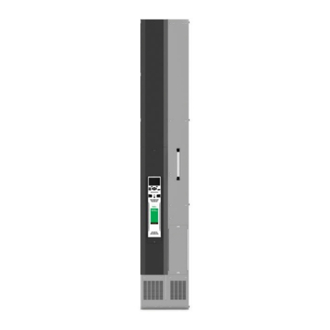
Nidec POWERDRIVE FX Series User manual

POWERDRIVE FX
Installation guide
4-quadrant
Variable speed drive
Part number: 4729 en - 2017.08 / c

2
POWERDRIVE FX Installation guide
4729 en - 2017.08 / c
LEROY-SOMER reverses the right to modify the characteristics of its products at any time in order to incorporate the latest
technological developments. The information contained in this document is therefore be changed without notice.
CAUTION
For the user’s safety, the variable speed drive must be connected to an approved earth ( terminal).
If accidentally starting the installation is likely to cause a risk to personnel or the machines being driven, it is essential to comply
with the power connection diagrams recommended in this manual.
The variable speed drive is tted with safety devices which, in the event of a fault, order it to stop and, at the same time, stop
the motor. The motor itself can become jammed for mechanical reasons. Voltage uctuations, and in particular power cuts, may
also cause the motor to stop. The removal of the causes of the shutdown can lead to restarting, which may be dangerous for
certain machines or installations.
In such cases, it is essential that the user takes appropriate precautions against the motor restarting after an unscheduled stop.
The variable speed drive is designed to be able to supply a motor and the driven machine above its rated speed.
If the motor or the machine are not mechanically designed to withstand such speeds, the user may be exposed to serious
danger resulting from their mechanical deterioration.
Before programming a high speed, it is important that the user checks that the installation can withstand it.
The variable speed drive which is the subject of this manual is designed to be integrated in an installation or an electrical
machine, and can under no circumstances be considered to be a safety device. It is therefore the responsibility of the machine
manufacturer, the designer of the installation or the user to take all necessary precautions to ensure that the system complies
with current standards, and to provide any devices required to ensure the safety of equipment and personnel.
Using the drive for hoisting: when using this application, it is essential to follow the special instructions in an application-specic
manual which is available on request. It is the responsibility of the user to obtain this manual from his usual LEROY-SOMER
contact.
LEROY-SOMER declines all responsibility in the event of the above recommendations not being observed.
........................................
This manual only describes the general features, characteristics and installation of the POWERDRIVE FX. For
commissioning, refer to manual ref.4617.
NOTE

3
POWERDRIVE FX Installation guide
4729 en - 2017.08 / c
SAFETY AND OPERATING INSTRUCTIONS FOR VARIABLE SPEED DRIVES
1 - General
Depending on their degree of protection, variable speed drives
may contain unprotected live parts, which may be moving or
rotating, as well as hot surfaces, during operation.
Unjustied removal of protection devices, incorrect use, faulty
installation or inappropriate operation could represent a
serious risk to personnel and equipment.
For further information, consult the documentation.
All work relating to transportation, installation, commissioning
and maintenance must be performed by experienced,
qualied personnel (see IEC 364 or CENELEC HD 384, or
DIN VDE 0100 and national specications for installation and
accident prevention).
In these basic safety instructions, qualied personnel means
persons competent to install, mount, commission and operate
the product, and possessing the relevant qualications.
2 - Use
Variable speed drives are components designed for integration
in installations or electrical machines.
When integrated in a machine, commissioning must not take
place until it has been veried that the machine conforms with
directive 2006/42/EC (Machinery Directive). It is also
necessary to comply with standard EN 60204, which stipulates
in particular that electrical actuators (which include variable
speed drives) cannot be considered as circuit-breaking
devices and certainly not as isolating switches.
Commissioning can taken place only if the requirements of the
Electromagnetic Compatibility Directive (EMC 2004/108/EC)
are met.
The variable speed drives meet the requirements of the
Low Voltage Directive 2006/95/EC. The harmonised
standards of the DIN VDE 0160 series in connection with
standard VDE 0660, part 500 and EN 60146/VDE 0558 are
also applicable.
The technical characteristics and instructions concerning the
connection conditions specied on the nameplate and in the
documentation provided must be observed without fail.
3 - Transportation, storage
All instructions concerning transportation, storage and correct
handling must be observed.
The climatic conditions specied in the technical manual must
be observed.
4 - Installation
The installation and cooling of equipment must comply with
the specications in the documentation supplied with the
product.
Variable speed drives must be protected against any excessive
stress. In particular, there must be no damage to parts and/or
modication of the clearance between components during
transportation and handling. Avoid touching electronic
components and contact parts.
The variable speed drives contain parts which are sensitive to
electrostatic stresses and may be easily damaged if handled
incorrectly. Electrical components must not be exposed to
mechanical damage or destruction (risks to health!).
5 - Electrical connection
When work is performed on variable speed drives which are
powered up, national accident prevention regulations must be
respected.
The electrical installation must comply with the relevant speci-
cations (for example conductor cross-sections, protection via
fused circuit-breaker, connection of protective conductor). More
detailed information is given int the documentation.
Instructions for an installation which meets the requirements
for electromagnetic compatibility, such as screening, earthing,
presence of lters and correct insertion of cables and
conductors, are given in the documentation supplied with the
variable speed drives. These instructions must be followed in
all cases, even if the variable speed drive carries the CE mark.
Adherence to the limits given in the EMC legislation is the
responsibility of the manufacturer of the installation or the
machine.
6 - Operation
Installations which incorporate variable speed drives must be
tted with additional protection and monitoring devices as
specied in current relevant safety regulations, such as the
law on technical equipment, accident prevention regulations,
etc. Modications to the variable speed drives using control
software are permitted.
Active parts of the device and the live power connections must
not be touched immediately after the variable speed drive is
powered down, as the capacitors may still be charged. In view
of this, the warnings xed to the variable speed drives must
be observed.
Permanent magnet motors generate electrical energy while
they are rotating, even when the drive is switched o. In this
case, the drive continues to be powered by the motor terminals.
If the load is capable of turning the motor, a switching device
must be provided upstream of the motor to isolate the drive
during maintenance operations.
During operation, all doors and protective covers must be kept
closed.
7 - Servicing and maintenance
Refer to the manufacturer’s documentation.
See the Maintenance section in this document.
This manual is to be given to the end user.
(In accordance with the low voltage directive 2006/95/EC)
Throughout the manual this symbol warns of consequences which may arise from inappropriate use of the drive, since
electrical risks may lead to material or physical damage as well as constituting a re hazard.

4
POWERDRIVE FX Installation guide
4729 en - 2017.08 / c
FOREWORD
This manual describes the installation of POWERDRIVE FX variable speed drives. It also gives details of all its options and
extensions which the user may choose to suit his requirements.
Compabloc
• Axial output
- Helical gears
Motors
Gearboxes
POWERDRIVE FX
• RFI filter
• Encoder or resolver input
• Additional I/O
• Datalogger
• Communication options
Options
HPM motor
Motor options
MDX-KEYPAD MDX-SOFT
parameter-setting
software
+ PC link cable
MDX-Powerscreen
parameter-setting
interface
Parameter setting
Orthobloc
• Orthogonal output
- Helical bevel gears Radial
forced
ventilation
LS-FLS motor
LSMV motor
LSRPM motor
Brake
Axial forced
ventilation
Encoder/Sensor

5
POWERDRIVE FX Installation guide
4729 en - 2017.08 / c
1 - GENERAL INFORMATION ................................................................................................................................ 7
1.1 - General........................................................................................................................................................ 7
1.2 - Product designation .................................................................................................................................... 7
1.3 - Environmental characteristics...................................................................................................................... 7
1.4 - Electrical characteristics .............................................................................................................................. 8
1.4.1 - General characteristics ......................................................................................................................................... 8
1.4.2 - Electrical characteristics at +40°C ........................................................................................................................ 8
1.4.3 - Derating according to the temperature and switching frequency .......................................................................... 8
2 - MECHANICAL INSTALLATION ...................................................................................................................... 10
2.1 - Checks on receipt ..................................................................................................................................... 10
2.2 - Dimensions................................................................................................................................................ 10
2.2.1 - Surface mounting ............................................................................................................................................... 10
2.2.2 - Through-panel mounting .................................................................................................................................... 12
2.3 - Weights...................................................................................................................................................... 14
2.4 - Losses, ventilation ow rate and noise levels ............................................................................................ 14
3 - CONNECTIONS................................................................................................................................................ 16
3.1 - Connection of the power ............................................................................................................................ 16
3.1.1 - Ratings 33T to 50T (size 2) ................................................................................................................................. 16
3.1.2 - Ratings 60T to 100T (size 3) ............................................................................................................................... 17
3.1.3 - Cables and fuses................................................................................................................................................. 18
3.2 - Connection of the control ........................................................................................................................... 19
3.2.1 - Locationof control terminal blocks ....................................................................................................................... 19
3.2.2 - Characteristics of control terminal blocks ............................................................................................................ 19
3.2.3 - Factory conguration of control terminal blocks .................................................................................................. 21
3.3 - STO-1 / STO-2 inputs: Safe Torque O function ........................................................................................................... 22
3.3.1 - 3-phase AC power supply, in accordance with safety standard IEC/EN62061: 2005 and EN/ISO 13849-1: 2006
- Single channel locking (SIL1 - PLb) ................................................................................................................................................ 22
3.3.2 - 3-phase AC power supply, in accordance with safety standard IEC/EN62061: 2005 and EN/ISO 13849-1: 2006
- Double channel locking with feedback (SIL3 - PLe) ...................................................................................................................... 22
4 - GENERAL EMC - HARMONICS - MAINS INTERFERENCE......................................................................... 23
4.1 - Low-frequency harmonics ......................................................................................................................... 23
4.2 - Radio-frequency interference: Immunity.................................................................................................... 23
4.2.1 - General ............................................................................................................................................................... 23
4.2.2 - Standards ........................................................................................................................................................... 23
4.2.3 - Recommendations ............................................................................................................................................. 23
4.3 - Radio-frequency interference: Emission.................................................................................................... 23
4.3.1 - General ............................................................................................................................................................... 23
4.3.2 - Standards ........................................................................................................................................................... 23
4.3.3 - Recommendations ............................................................................................................................................. 23
4.4 - Mains power supply ................................................................................................................................... 23
4.4.1 - General ............................................................................................................................................................... 23
4.4.2 - Mains transient overvoltages .............................................................................................................................. 23
4.4.3 - Mains short-circuit power .................................................................................................................................... 24
4.4.4 - Ground connections ........................................................................................................................................... 24
4.5 - Basic precautions for installation ............................................................................................................... 24
4.5.1 - Wiring inside the cabinet...................................................................................................................................... 24
4.5.2 - Wiring outside the cabinet ................................................................................................................................... 24
4.6 - Electromagnetic compatibility (EMC)......................................................................................................... 25
5 - OPTIONS .......................................................................................................................................................... 26
5.1 - Operator interfaces.................................................................................................................................... 26
5.1.1 - Connection to the drive........................................................................................................................................ 26
5.1.2 - MDX-KEYPAD .................................................................................................................................................... 26
5.1.3 - MDX-Powerscreen ............................................................................................................................................. 27
5.1.4 - MDX-SOFT ......................................................................................................................................................... 27
CONTENTS

6
POWERDRIVE FX Installation guide
4729 en - 2017.08 / c
5.2 - Add-on options........................................................................................................................................... 28
5.2.1 - Connector and shielding bracket ........................................................................................................................ 28
5.2.2 - Fieldbus, speed feedback and I/O options .......................................................................................................... 28
5.2.3 - Fieldbus options ................................................................................................................................................. 28
5.2.4 - Speed feedback options ..................................................................................................................................... 29
5.2.5 - I/O options .......................................................................................................................................................... 29
5.3 - RFI lters ................................................................................................................................................... 30
5.3.1 - General ............................................................................................................................................................... 30
5.3.2 - Weight and dimensions ...................................................................................................................................... 30
6 - TRIPS - DIAGNOSTICS ................................................................................................................................... 31
6.1 - Drive statut ................................................................................................................................................ 31
6.2 - Alarms ....................................................................................................................................................... 32
6.3 - Trips .......................................................................................................................................................... 32
7 - MAINTENANCE ............................................................................................................................................... 35
7.1 - Servicing ................................................................................................................................................... 35
7.2 - Storage ..................................................................................................................................................... 35
7.3 - Exchanging products ................................................................................................................................ 35
8 - UL LISTING INFORMATION ........................................................................................................................... 36
8.1 - Common UL information ........................................................................................................................... 36
8.2 - AC supply specication ............................................................................................................................. 36
8.3 - Maximum continuous current .................................................................................................................... 36
8.4 - Fusing and cabling .................................................................................................................................... 36
CONTENTS

7
GENERAL INFORMATION
POWERDRIVE FX Installation guide
4729 en - 2017.08 / c
1 - GENERAL INFORMATION
1.1 - General
The POWERDRIVE FX is an electrical drive with ux vector
control, designed for supplying asynchronous or synchronous
3-phase motors.
The POWERDRIVE FX has a rectier with IGBT bridge
controlled at the frequency of the mains supply, which has the
following advantages:
- Motor energy feedback to the mains supply (operation in all 4
quadrants of the torque/speed plane without energy
dissipation),
- Limiting of the level of current harmonics generated on the
power supply line, at a much lower level than that of a
conventional 6-pilse drive using a line reactor.
The POWERDRIVE FX is a variable speed drive with very high
performance levels that can be used to control:
- Induction motors without speed sensor (Open loop mode
select ) for applications that do not need rated torque
control above 1/10th of the rated speed.
- Asynchronous or synchronous permanent magnet motors
with virtual speed feedback (Flux vector mode with software
sensor function ) for applications that require rated torque
control from 1/20th of the rated speed.
Combined with the MDX-ENCODER option, the
POWERDRIVE FX is a drive that can also be used to control
asynchronous or synchronous magnet machines for
applications that require very high dynamic performances or
torque control from zero speed (Closed loop vector mode with
speed feedback ).
• POWERDRIVE FX drives are designed for
installation in a cabinet or an enclosure to ensure
protection from conducting dust and condensation.
Prevent access by unauthorised personnel.
Diagram
Micro-
controller
I/O
control
Mains
supply
PWM
Optional
sensor
MDX-
ENCODER
(optional)
Control board
M
1.2 - Product designation
POWERDRIVE FX 33 T
Rating in kVA
3-phase
power supply
400V to 480V (T)
4-quadrant variable
speed drive with
flux vector control
Nameplate
The nameplate is located at the bottom right-hand side of
the product (front view).
1.3 - Environmental characteristics
Characteristics Level
Protection
IP20
Storage and transport
temperature
-30°C to +70°C
Ambient operating
temperature
(outside the cabinet)
-10°C to +40°C, up to +50°C with
derating
(see section 1.4.3)
Classication of
environmental
conditions
In accordance with
IEC 60721-3-3 :
• Biological classication in
accordance with class 3B1,
• Classication as regards
chemically active substances in
accordance with class 3C2,
• Classication as regards
mechanically active substances
in accordance with class 3S2
Relative humidity
• In accordance with
IEC 60068-2-56
• < 90% non condensing
Altitude
• ≤ 1000 m without derating
• > 1000 m: operating
temperature derating of 0.6°C
per 100 m, up to 4000 m
maximum
E.g. for an altitude of 1300 m, the
electrical characteristics must be
taken into account for an ambient
temperature of:
[40° - (3 x 0.6°)] = 38.2°C
Vibrations
• In accordance with
IEC 60068-2-6
• Non-packaged product: 2m/s2
(9-200Hz), 0.6mm (2-9Hz)
• Packaged product: 10m/s2
(9-200Hz), 3mm (2-9Hz)
Shocks
Packaged product: in
accordance with IEC 60068-2-29
Atmospheric pressure
700 to 1060 hPa

8
GENERAL INFORMATION
POWERDRIVE FX Installation guide
4729 en - 2017.08 / c
1.4 - Electrical characteristics
• All work relating to installation, commissioning and maintenance must be carried out by experienced, qualied
personnel.
1.4.1 - General characteristics
Characteristics Level
Power supply voltage 3-phase mains supply: 400V -10% to 480V +6%
Phase voltage imbalance < 3%
Input frequency 2% around te rated frequency (50 or 60 Hz)
Maximum number of power-ups per hour (power) • 20
Output frequency range 0 to 200 Hz
Mains short-circuit capability at the point of connection See section 4.4.3
ROHS conformance Conforming to standard 2002-95-EC
1.4.2 - Electrical characteristics at +40°C
Ico: Continuous output current
Pout: Output power
Imax (60s): Maximum output current*
Heavy duty: For high overload constant torque machines (presses, grinders, hoists, etc) and all applications where signicant inertia
has to be accelerated quickly (centrifuges, translation of travelling cranes, etc).
Normal duty: For low overload constant torque or centrifugal torque machines (fans, compressors, etc).
*: Current available for 60 seconds every 600 seconds.
The output currents Ico in the table below are given for:
- A 4 kHz switching frequency,
- An ambient temperature of +40°C,
- An altitude of 1000m maximum.
POWERDRIVE FX Heavy duty Normal duty
Size Rating
P
out
kW
I
co
A
I
max
(60s)
A
P
out
kW
I
co
A
I
max
(60s)
A
2
33T
22
45
68
30
59
64
40T
30
59
89
37
73
79
50T
37
73
105
45
86
95
3
60T
45
92
135
55
110
119
75T
55
110
165
75
145
157
100T
75
145
200
90
175
189
1.4.3 - Derating according to the temperature and switching frequency
POWERDRIVE FX
rating Duty
I
co
(A)
4kHz
5kHz
6kHz
33T
Heavy
45
43
41
Normal
59
56
53
40T
Heavy
59
55
50
Normal
73
68
62
50T
Heavy
73
68
63
Normal
86
80
74
60T
Heavy
92
88
84
Normal
110
106
100
75T
Heavy
110
100
88
Normal
145
132
116
100T
Heavy
145
131
113
Normal
175
158
137
The Ico output currents are given at an ambient temperature of +40°C. For a temperature above +40°C, derate the current by 1.5%
for every additional degree up to a maximum temperature of +50°C.

9
GENERAL INFORMATION
POWERDRIVE FX Installation guide
4729 en - 2017.08 / c
Notes

10
MECHANICAL INSTALLATION
POWERDRIVE FX Installation guide
4729 en - 2017.08 / c
2 - MECHANICAL INSTALLATION
• It is the responsibility of the owner or user of the
POWERDRIVE FX to ensure that the installation,
operation and maintenance of the drive and its options
comply with legislation relating to the safety of personnel
and equipment and with the current regulations of the
country of use.
• POWERDRIVE FX drives must be installed in an
environment free from conducting dust, corrosive
fumes, gases and uids, and condensation (class 2
according to IEC 664.1). the drive must not be installed in
hazardous areas unless it is in an appropriate enclosure.
In this case, the installation must be approved.
• In atmospheres where condensation may form, install
a heating system (to be switched o when the drive is
operating). It is advisable to control the heating system
automatically.
• The casing of the POWERDRIVE FX is not reproof.
If necessary, use a ameproof cabinet.
2.1 - Checks on receipt
Before installing the POWERDRIVE FX, check that:
- The drive has not been damaged during transport,
- The information on the nameplate is compatible with the
power supply.
2.2 - Dimensions
CAUTION:
In the cabinet, there must be a minimum distance of
100 mm between two drives, and 200 mm above and
below the drive.
2.2.1 - Surface mounting
2.2.1.1 - Ratings 33T to 50T
200
256
587
575
175 15
240*
Ø
Front view Side view
Lifting rings
Fixed with
4 M6 screws
Dimensions in mm
(*) •With MDX-I/O M2M option, add +25mm
•With MDX-ENCODER, MDX-RESOLVER, MDX-I/O Lite
or MDX-Fieldbus option, add +30mm
(the 2 option types can be combined, add +55mm)

11
MECHANICAL INSTALLATION
POWERDRIVE FX Installation guide
4729 en - 2017.08 / c
2.2.1.2 - Ratings 60T to 100T
250
188
50 50
17
750 692 766
782 788
45
Ø
284*
78.5
53.5
32.5
49.5
37.4
Lifting rings
Fixed with
4 M8 screws
Terminal block
cover
Terminal block
cover
Front view Side view
Dimensions in mm
(*) •With MDX-I/O M2M option, add +25mm
•With MDX-ENCODER, MDX-RESOLVER, MDX-I/O Lite
or MDX-Fieldbus option, add +30mm
(the 2 option types can be combined, add +55mm)

12
MECHANICAL INSTALLATION
POWERDRIVE FX Installation guide
4729 en - 2017.08 / c
2.2.2 - Through-panel mounting
CAUTION:
To obtain IP54 protection at the back of the heatsink, an additional seal is needed (not supplied, adhesive strip of EPDM
rubber or equivalent).
The POWERDRIVE FX is delivered with its xing feed mounted, ready for surface mounting. For through-panel mounting, remove
the feet, and follow the instructions below.
2.2.2.1 - Ratings 33T to 50T
530
200
18
495
Ø
553
486
140*
15
Ø
> 40
231
for M6 crimp
cap nuts
Lifting rings
Solid
surface
Back of
the cabinet
seal
seal
Drill hole diagram Side view
85.5
15.5
Dimensions in mm
(*)
•With MDX-I/O M2M option, add +25mm
•With MDX-ENCODER, MDX-RESOLVER, MDX-I/O Lite
or MDX-Fieldbus option, add +30mm
(the 2 option types can be combined, add +55mm)

13
MECHANICAL INSTALLATION
POWERDRIVE FX Installation guide
4729 en - 2017.08 / c
2.2.2.2 - Ratings 60T to 100T
225
228 709
750
23
788
162*
> 40
106
Ø
17
Ø
1.5
78.5
49.5
700.6
for M8
crimp cap nuts
Solid
surface
Back of
the cabinet
Lifting rings
Terminal block
cover
Terminal block
cover
Drill hole diagram Side view
seal
seal
53.5
Dimensions in mm
(*) •With MDX-I/O M2M option, add +25mm
•With MDX-ENCODER, MDX-RESOLVER, MDX-I/O Lite
or MDX-Fieldbus option, add +30mm
(the 2 option types can be combined, add +55mm)

14
MECHANICAL INSTALLATION
POWERDRIVE FX Installation guide
4729 en - 2017.08 / c
2.3 - Weights
POWERDRIVE FX rating 33T 40T 50T 60T 75T 100T
Weight (kg) 20 37
• Suitable handling equipment must be provided according to the weight of the drives.
2.4 - Losses, ventilation ow rate and noise levels
• Losses
Losses*
(W)
POWERDRIVE FX
33T
40T
50T
60T
75T
100T
Total 800 980 1150 1450 1850 2200
Inside the cabinet
(through-panel mounting)
90 100 110 140 170 200
(*) Maximum losses for normal duty operation at the Ico output currents given in section 1.4.3.
• Forced ventilation ow rates
Forced
ventilation
POWERDRIVE FX
33T
40T
50T
60T
75T
100T
Flow rate
(m
3
/h)
230 340
• Noise
Forced
ventilation
POWERDRIVE FX
33T 40T 50T 60T 75T 100T
Level
(dBA)
52 56

15
MECHANICAL INSTALLATION
POWERDRIVE FX Installation guide
4729 en - 2017.08 / c
Notes

16
CONNECTIONS
POWERDRIVE FX Installation guide
4729 en - 2017.08 / c
3 - CONNECTIONS
• All connection work must be performed in
accordance with the laws in force in the country in
which the drive is installed. This includes earthing to
ensure that no directly accessible part of the drive can be
at the mains voltage or any other voltage which may be
dangerous, a source of serious injury, malfunctions or
electromagnetic interference.
• The voltages on the cables or connections of the
mains supply, the motor or the lter may cause fatal
electric shocks. Contact with these items must be avoided
under all circumstances.
• The drive must be supplied via a circuit-breaking
device so that it can be powered down safety.
• The drive power supply must be protected against
overloads and short-circuits.
• The drive stop function does not protect against
high voltages on the terminal blocks.
• Check that the voltage and current of the drive, the
motor and the mains supply are compatible.
• After the drive has been operating, keep away from
the heatsink as it may be very hot (+70°C).
• When the drive controls a permanent magnet
motor, only one motor can be connected to the drive output.
It is advisable to install a circuit-breaking device between
the permanent magnet synchronous motor and the drive
output. This breaker isolates the motor during maintenance
work on the drive.
3.1 - Connection of the power
3.1.1 - Ratings 33T to 50T (size 2)
MDX-ENCODER
and/or
Fieldbus option
Screw terminal
blocks: M6
Tightening
torque: 4 Nm
Screw terminal blocks: M6
Tightening torque: 4 Nm
QS
Mains supply
Optional
RFI filter
Optional
sensor
3-phase motor
(asynchronous or
synchronous)
U V W PE
L1 L2 L3 PE
QS: Fused isolator. QS must be opened before working on any
electrical parts of the drive or motor.

17
CONNECTIONS
POWERDRIVE FX Installation guide
4729 en - 2017.08 / c
3.1.2 - Ratings 60T to 100T (size 3)
L1 L2 L3 PE
U V W
PE
Screw bolt: M8
Tightening
torque: 12 Nm
Screw bolt: M8
Tightening
torque: 12 Nm
QS
Mains supply
Optional
RFI filter
Optional
sensor
3-phase motor
(asynchronous or
synchronous)
MDX-ENCODER
and/or
Fieldbus option
QS: Fused isolator. QS must be opened before working on any
electrical parts of the drive or motor.

18
CONNECTIONS
POWERDRIVE FX Installation guide
4729 en - 2017.08 / c
3.1.3 - Cables and fuses
• It is the responsibilityof the user to connect and provide protection for the POWERDRIVE FX in accordance with the
current legislation and regulations in the country of use. This is particularly important as regards the size of the
cables, the type and rating of fuses, the earth or ground connection, powering down, acknowledging trips, isolation and
protection against overcurrents.
• This table is given for information only, and must under no circumstances be used in place of the current standards.
Ico: Continuous output current
ILM: Maximum continuous line current permitted in motor mode (power drawn by the motor)
ILG: Maximum continuous line current permitted in regenerative mode (power transmitted to the mains supply)
POWERDRIVE FX Mains supply Motor (1)
400V - 50Hz
460/480V - 60Hz
Ico
(A)
Cable
cross-
sections
(2)
(mm2)
Rating /
duty
ILM
(A)
ILG
(A)
Fuses Cable
cross-
sections
(2)
(mm2)
ILM
(A)
ILG
(A)
Fuses Cable
cross-
sections
(2)
(mm2)
Gg
type
aR
type
Gg
type
aR
type
Class
J
33T
Heavy
42
34
50
80
3x10 + 10
37
30
50
80
60
3x10 + 10
45
3x10 + 10
Normal
57
45
63
100
3x16 + 16
50
39
63
100
80
3x16 + 16
59
3x16 + 16
40T
Heavy
57
45
63
100
3x16 + 16
50
39
63
100
80
3x16 + 16
59
3x16 + 16
Normal
68
55
80
125
3x25 + 15
59
48
80
125
100
3x25 + 16
73
3x25 + 16
50T
Heavy
68
55
80
125
3x25 + 16
59
48
80
125
100
3x25 + 16
73
3x25 + 16
Normal
83
66
100
160
3x25 + 16
72
57
100
160
125
3x25 + 16
86
3x25 + 16
60T
Heavy
83
66
100
160
3x25 + 16
72
57
100
160
125
3x35 + 16
92
3x35 + 16
Normal
100
80
125
200
3x50 + 25
87
70
125
200
150
3x35 + 16
110
3x50 + 25
75T
Heavy
100
80
125
200
3x50 + 25
87
70
125
200
150
3x35 + 16
110
3x50 + 25
Normal
135
108
160
250
3x70 + 35
117
94
160
250
200
3x70 + 35
145
3x70 + 35
100T
Heavy
135
108
160
250
3x70 + 35
117
94
160
250
200
3x70 + 35
145
3x70 + 35
Normal
162
130
200
350
3x95 + 50
141
113
200
350
225
3x70 + 35
175
3x95 + 50
(1) The value of the rated current and the motor cable cross-sections are given for information only. As a reminder, the motor rated
current permitted by the drive varies according to the switching frequency and the temperature.
(2) The recommended cross-sections have been determined for single-conductor copper cable with a maximum length of 10 m.
For longer cables, take line drops due to the length into account.
Note:
• The cable cross-sections are dened according to the following model:
E.g. for a 100T drive in normal duty, a cable cross-section of (3 x 95 + 50) is given, i.e. 1 bundle consisting of 3 phase conductors
(cross-section 95) and 1 earth conductor (cross-section 50).
• The Ico output currents are given at an ambient temperature of 40°C. For a temperature above 40°C, derate the current by 1.5%
for every additional degree up to a maximum temperature of 50°C.

19
CONNECTIONS
POWERDRIVE FX Installation guide
4729 en - 2017.08 / c
3.2 - Connection of the control
• The POWERDRIVE FX inputs have a positive logic
conguration. Using a drive with a control system
which has a dierent control logic may cause unwanted
starting of the motor.
• The POWERDRIVE FX control circuit is isolated
from the power circuits by single insulation. Its electronic
0V is connected to the connection terminal on the outer
protective conductor (earth terminal). The installer must
ensure that the external control circuits are isolated
against any human contact.
• If the control circuits need to be connected to
circuitconformingto SELV safetyrequirements,additional
insulation must be inserted to maintain the SELV
classication (see EN 61140).
3.2.1 - Location of control terminal blocks
Px1 Px2 Px3
Clamps for connecting the
control cable shield
Control terminal blocks
RL1 status relay LED
RL2 status relay LED
P1 P2
111
Px1 Px2 Px3
1 1 1
Control terminal block
Removable screw terminal block: tightening torque = 0.3 N.m/0.22 lb ft
cross-section = 1.5 mm2
screwdriver = 2 mm flat
Analog I/O Digital I/O Relays
3.2.2 - Characteristics of control terminal
blocks
3.2.2.1 - Characteristics of the PX1 terminal block
110V +10 V internal analog source
Accuracy ± 2%
Maximum output current 10 mA
2AI1+ Dierential analog input 1 (+)
3AI1- Dierential analog input 1 (-)
Factory setting 0-10 V speed reference
Input type
±10 V dierential bipolar
analog voltage (for common
mode, connect terminal 3 to
terminal 6)
Absolute maximum voltage
range ± 36 V
Voltage range in common
mode ± 24V / 0 V
Input impedence > 100 kΩ
Resolution 11 bits + sign
Sampling period 2 ms
Input lter bandwidth ~ 200 Hz
4AI2+ Dierential analog input 2 (+)
5AI2- Dierential analog input 2 (-)
Factory setting 0-20 mA speed reference
Input type Unipolar current
(0 to 20 mA, 4 to 20 mA,
20 to 0 mA, 20 to 4 mA)
Absolute maximum current 30 mA
Voltage range in common
mode ± 24 V / 0 V
Input impedence 100 kΩ
Resolution 12 bits
Sampling period 2 ms
Input lter bandwidth ~ 200 Hz
60V Analog circuit common 0 V
The 0 V on the electronics is connected to themetal ground
of the drive
7AI3 Analog input 3
Factory setting No assignment
Input type
± 10 V bipolar analog voltage
in common mode or unipolar
current
(0 to 20 mA, 4 to 20 mA)
Resolution 11 bits + sign
Sampling period 2 ms
Input lter bandwidth ~ 200 Hz
Voltage range in common
mode ± 24 V / 0 V
Voltage mode
Input impedence > 50 kΩ
Absolute maximum voltage
range ± 30 V
Current mode
Input impedence 100 Ω
Absolute maximum current 30 mA

20
CONNECTIONS
POWERDRIVE FX Installation guide
4729 en - 2017.08 / c
8AO1 Analog output
Factory setting 4-20 mA motor current signal
Output type Bipolar analog voltage in
common mode or unipolar
current in common mode
Resolution 13 bits
Sampling period 2 ms
Voltage mode
Voltage range ± 10 V
Load resistance 1 kΩ minimum
Current mode
Current range 0 to 20 mA, 4 to 20 mA
Load resistance 500 Ω maximum
9DI1/CTP PTC thermal sensor or
Digital input DI1
Factory setting No assignment
Sampling period 2 ms
Motor thermal sensor input
Voltage range ± 10 V
Trip threshold > 3.3 Ω
Reset threshold < 1.8 Ω
Digital input
Type Digital input in positive logic
Voltage range 0 to + 24 V
Absolute maximum voltage
range 0V to + 35 V
Thresholds 0: < 5 V
1: > 13 V
10 0V Analog circuit common 0 V
The 0 V on the electronics is connected to the metal ground
of the drive
3.2.2.2 - Characteristics of the PX2 terminal block
1+24V ref +24 VDC user output or
+24 VDC external input
9
+24 VDC user output
Output current 100 mA
Accuracy ± 5%
Protection Current limitig and setting to
trip mode
+24 VDC external input
Rated voltage 24 VDC
Minimum operating voltage 22 V
Absolute maximum voltage 28 V
Recommended power 50 W
Recommended fuse 2.5 A
An external power supply connected to the +24 V Ref
terminal is used to maintain the control power supply in the
event of mains loss
2DO1 Digital output
Factory setting Zero speed
Characteristics Open collector
Absolute maximum voltage + 30 V / 0 V
Overload current 200 mA
3STO-1 Drive enable input 1
(Safe Torque O function)
6STO-2 Drive enable input 2
(Safe Torque O function)
Input type Positive logic only
Absolute maximum voltage + 30 V
Thresholds 0: < 5 V
1: > 13 V
Response time < 20 ms
4DI2 Digital input DI2
5DI3 Digital input DI3
7DI4 Digital input DI4
8DI5 Digital input DI5
DI2 factory setting Selection of speed reference
DI3 factory setting
DI4 factory setting Run FWD/Stop input
DI5 factory setting Run reverse/Stop input
Type Digital inputs in positive logic
Voltage range 0 to + 24 V
Absolute maximum voltage
range 0 to + 35 V
Thresholds 0: < 5 V
1: > 13 V
3.2.2.3 - Characteristics of the PX3 terminal block
1COM-RL1 N/O (normally open) relay output
2RL1
Factory setting Drive status relay
Voltage 250 VAC
Maximum contact current
• 2 A - 250 VAC,
resistive load
• 1 A - 250 VAC,
inductive load
• 2 A - 30 VDC,
resistive load
3COM-RL2 N/O (normally open) relay output
4RL2
Factory setting Vmax alarm
Voltage 250 VAC
Maximum contact current
• 2 A - 250 VAC,
resistive load
• 1 A - 250 VAC,
inductive load
• 2 A - 30 VDC,
resistive load
• Provide a fuse or other overcurrent protection
in the relay circuit.
Note:
When the RL1 or RL2 relay is activated, the corresponding
status LED on the control board lights up (see diagram in
section 3.2.1).
This manual suits for next models
6
Table of contents
Other Nidec Inverter manuals

Nidec
Nidec Leroy-Somer LSA 46.3 Instruction Manual

Nidec
Nidec Leroy-Somer POWERDRIVE MD2CS User manual

Nidec
Nidec Unidrive M Series User manual

Nidec
Nidec LAROY-SOMER LSA 44.3 Instruction Manual

Nidec
Nidec Unidrive M700 User manual

Nidec
Nidec Leroy Somer Powerdrive MD2SL Series Instruction Manual

Nidec
Nidec LEROY-SOMER LSA 40 Instruction Manual

Nidec
Nidec Leroy-Somer Gearlec Series Instruction Manual