HG200 - 200 Inverter
The machine must be periodically inspected
(on a six-month or yearly basis) to check the
general use conditions (e.g. leaking grease,
condition of electric power supply cables
and machine control components, condition
of the support structure, etc.).
In particular:
- The cables must be checked every three
months and replaced immediately if there are
any breaks in the elementary wires, or if they
are twisted, smashed, bent, if knots have
formed or if there is any other serious
deterioration (heavy rust formation) or if
heavily worn.
- The above-mentioned inspections must be
reported on a special chart (see appendix
page), indicating the date of the inspection
and the signature of the tester.
- The braking system must be checked every
six months and, in any case, each time that,
during normal machine use, the load does
not stop immediately.
- The distance between the brake disk and
electromagnets is adjusted using the set nut
located at the end of the motor shaft.
It must range between 0.3-0.5 mm.
- The cable, hook and braking system
register must be replaced by skilled
personnel or at a TEA service centre.
REPAIRS
Repairs may be performed at a TEA service
centre.
The user can request a list of authorised
service centres at any time from dealers or
directly from the manufacturer.
REQUEST FOR SPARE PARTS
A special manual includes tables with the
drawings and the names of the various parts
of the hoist. The code number is indicated
next to the name of each part.
The request for spare parts must be
submitted to a TEA service centre or to a
dealer.
It must include the following:
a) hoist model and serial number;
b) piece position number or relative code;
c) quantity requested.
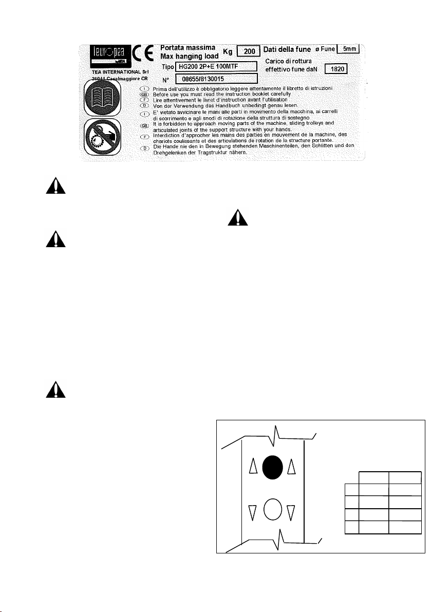
Instructions for hoist
Mod HG200 200- INVERTER
This instructions sheet is an integral
part of the instructions manual for the
HG200-2O0 INVERTER 210- hoist It is
essential to comply with any safety
instructions and warnings provided in the
above manual
Removing the seals of guarantee located on
the housing of the device is prohibited The
guarantee will be invalidated in case of
tampering
Before connecting the plug to the mains
power supply, check that the knob located
on the box containing the device is in
position 0 (OFF)
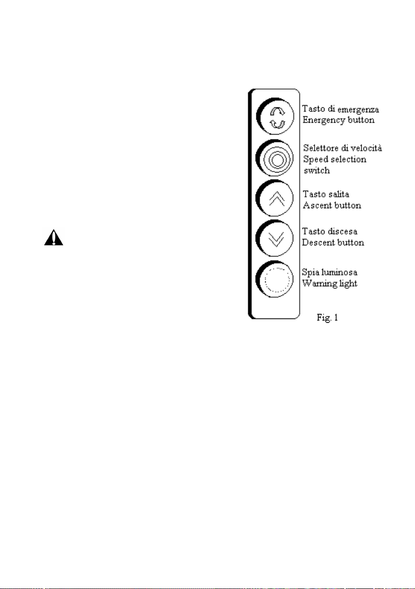
Operation
The hoist is controlled by means of its
dedicated push button control unit, which is
fitted with the following buttons and
indicators:
1. Two push buttons for operation
(ascent and descent)
2. An emergency push button
3. A speed selection switch
4. A warning light
•Turn the starter knob to position 1 (ON).
•Check that the green warning light, located
at the bottom of the push button control
unit, is on (Fig.1).
•Select the hoist operating speed using its
speed selection switch (Fig. 1): there are 4
possible operating speeds. To increase the
speed, turn the switch clockwise.
•For hoist ascent, check that the emergency
button is off and press the top white
button. Press the button lightly to operate
the hoist with its lowest speed, press down
fully to operate the hoist at the selected
speed (Attention: the speed will increase
English