6
DATA FORMAT: Format of Entire Data
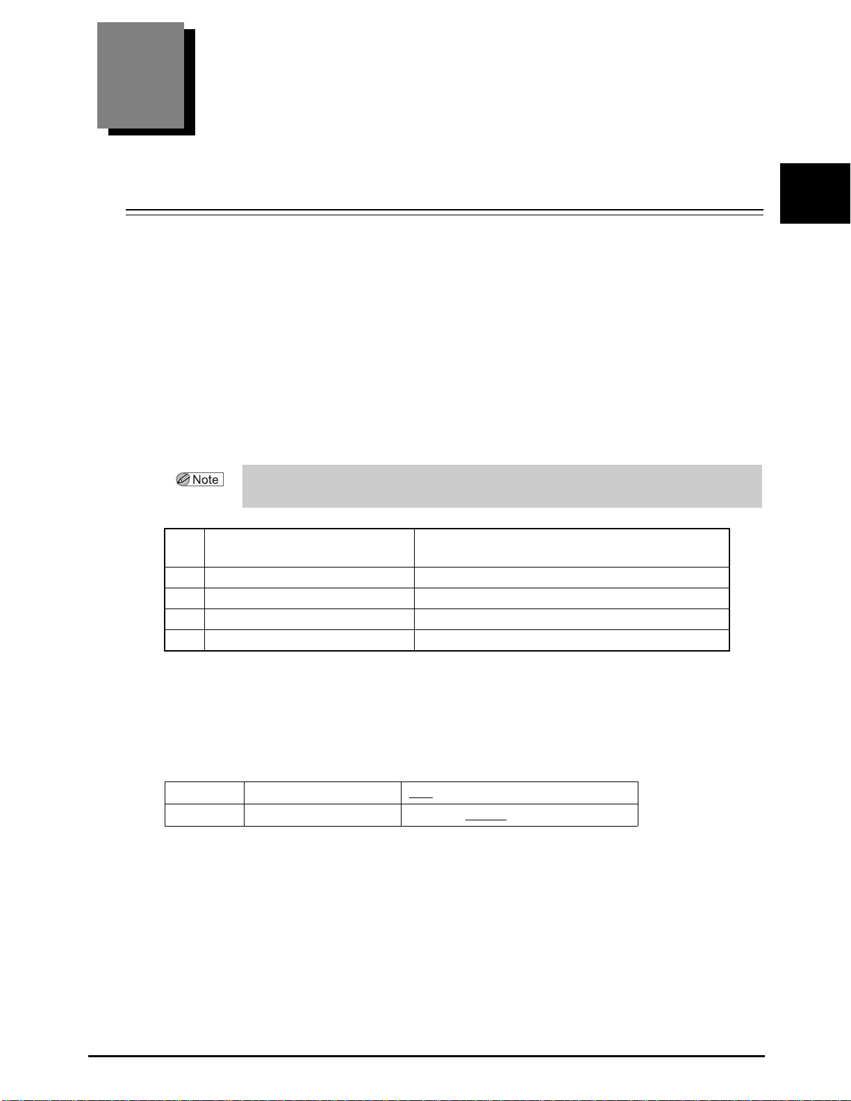
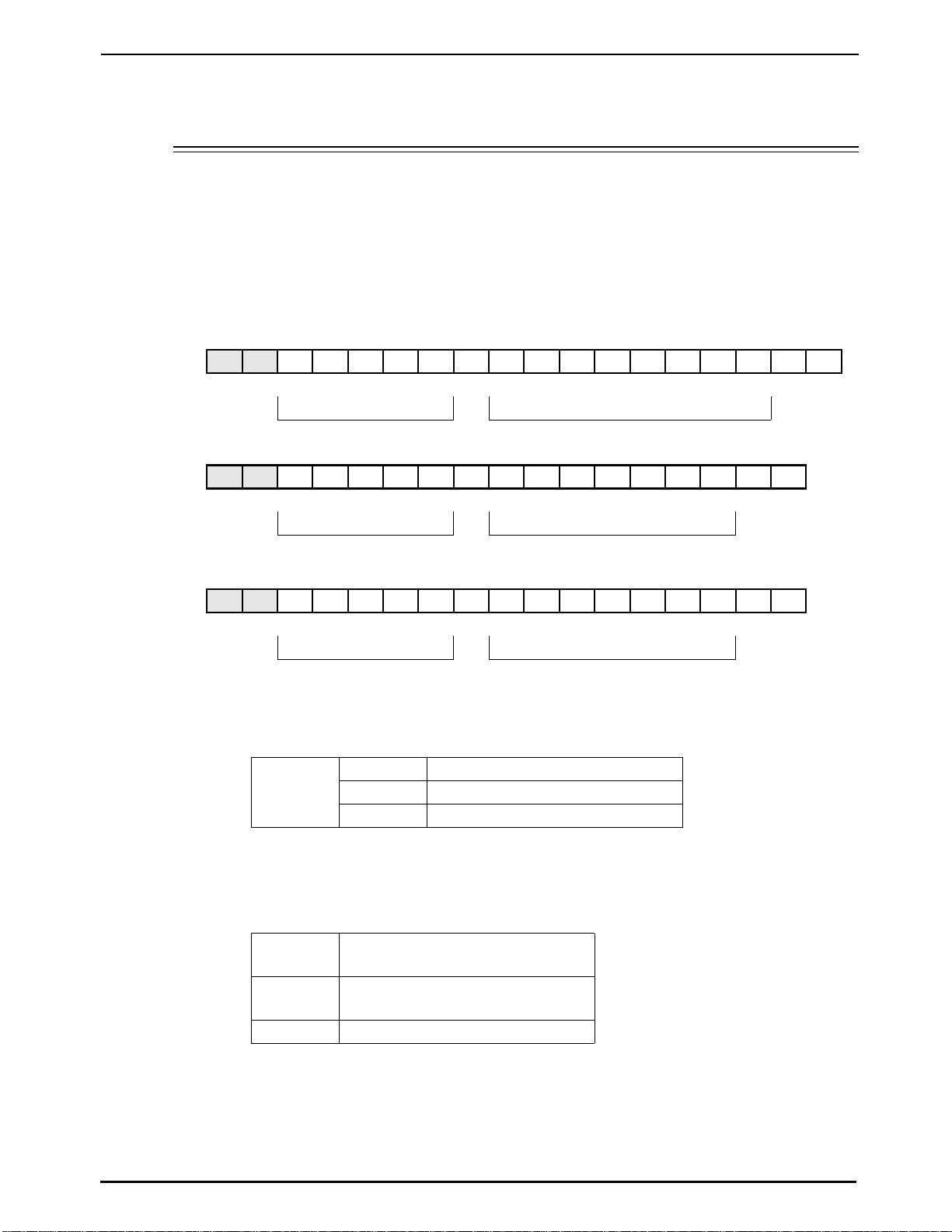
(4)NEDEK ID
Character string of the company and model names.
LM-1000P
LM-1000
LM-1200
* In the lower line, the ASCII code of each character is represented by hexadecimals.
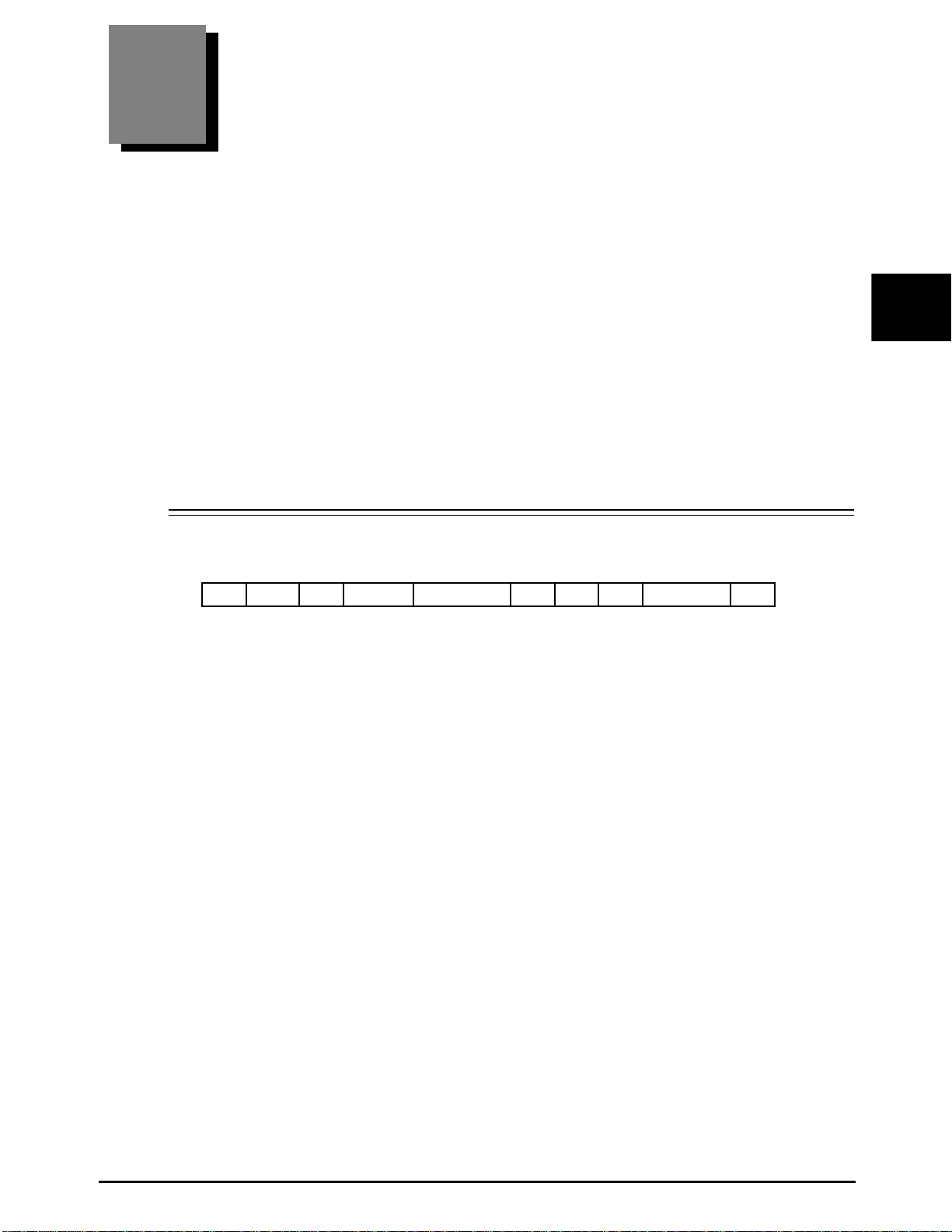
The first two characters, “ID”, that is referred to as an identification code of the character
string represents the type of the data that follows. The identification code that is also added
to the head of the measured data is used for searching for desired data. The latter ETB, a
communication control character, represents “a delimiter of data”. Some software on the
computer needs the CR code at the end that represents “the end of the character string”. As
necessary, set the CR Code parameter.
(5) Measured data, (6) ETB, (7) CR
See “2.2. Format of each data (Page 8)”.
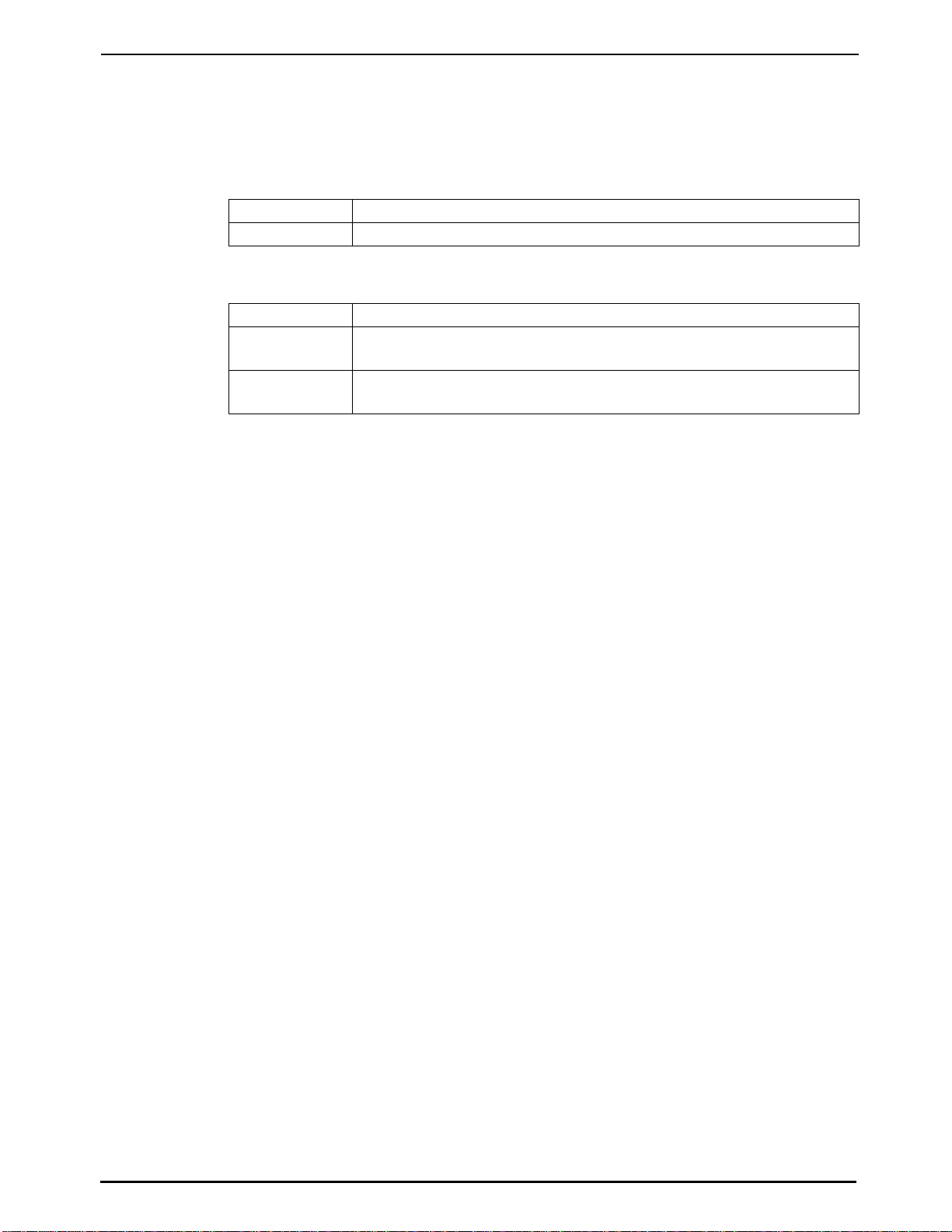
(8)EOT(04H)
This is a communication control character that represents “the end of the character string”.
In the case of measured data, this character represents the end of data.
(9)CS1 - CS4, (10) CR
This is a checksum for error detection. The value of the checksum is the simple sum of
“SOH” at the head to “EOT” in the data format except the CR code. The hexadecimal num-
bers in the low-order two bytes are represented by four-byte ASCII codes as a simple sum of
SOH at the head of the data to “EOT (04H)”. The checksum is calculated from the data
received by the computer in the same way. Normal data reception is identified by an agree-
ment between both sums.
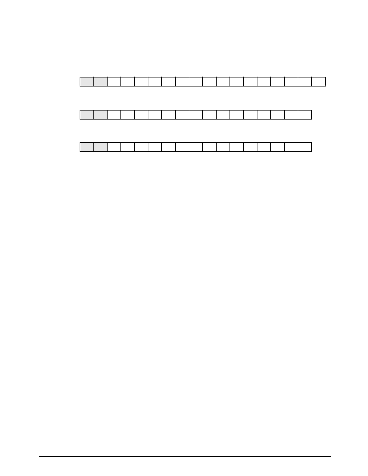
IDNIDEK/LM-1000PETBCR
49H 44H 4EH 49H 44H 45H 4BH 2FH 4CH 4DH 2DH 31H 30H 30H 30H 50H 17H 0DH
IDNIDEK/LM-1000ETBCR
49H 44H 4EH 49H 44H 45H 4BH 2FH 4CH 4DH 2DH 31H 32H 30H 30H 17H 0DH
IDNIDEK/LM-1200ETBCR
49H 44H 4EH 49H 44H 45H 4BH 2FH 4CH 4DH 2DH 31H 32H 30H 30H 17H 0DH