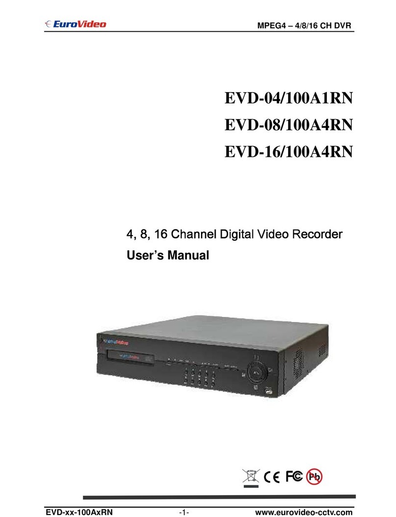
Night Watcher 8 channel D1 Realtime DVR User manual


1
Connection Diagram
English
Connect the BNC outputs from
your cameras into the yellow BNC
inputs on the rear of the DVR.
Connect your cameras to
power, using the a power-
splitter (if included).
Connect the DC12V
Output from the
power supply to
the power input.
Connect the power
supply to a wall
outlet.
Connect the mouse
to the USB2.0 port.
If you’ve got a monitor with VGA
but not HDMI, connect it to the VGA
output on the DVR.
If you’ve got aTV or monitor
with HDMI in, connect to
the HDMI port on the DVR.
Connect an ethernet
cable from the LAN port
on the DVR to a spare
port on your router.

2
The Audio Out port
can be used to connect
a stereo, speakers,
headphones or other
external sound device.
The Audio In ports can be used
to connect audio devices to the
DVR. Obviously, your microphone
probably won’t look like that one
- they’re often built into cameras.
An external hard drive
with an eSATA port can
be connected to the
eSATA port on the DVR.
The front USB port also supports USB solid-
state storage, such as ash drives.
The PTZ port (RS485)
can be used to connect
compatible PTZ devices,
such as this Swann PTZ
dome.
Connect the mouse to the USB2.0 port

3
CE, FCC, RoHS Verification
NOTE: This equipment has been tested and found to comply with the limits for the CE, FCC, RoH
rules. These limits are designed to provide reasonable protection against harmful interference in a
residential installation. This equipment generates, uses and can radiate radio frequency energy and, if
not installed and used in accordance with the instructions, may cause harmful interference to radio or
television reception, which can be determined by turning the equipment off and on, the user is
encouraged to try to correct the interference by one or more of the following measures:
* Reorient or relocate the receiving antenna
* Increase the separation between the equipment and the receiver
* Connect the equipment into an outlet on a circuit different from that to which the receiver is
connected
* Consult the dealer or an experienced radio/TV technician for help
These devices comply with the CE Rules. Operation is subject to the following two conditions:
1. These devices may not cause harmful interference, and
2. These devices must accept any interference received, including interference that may cause
undesired operation.
IMPORTANT NOTE:
All jurisdictions have specific laws and regulations relating to the use of cameras. Before using any
camera for any purpose, it is the buyer’s responsibility to be aware of all applicable laws and
regulations that prohibit or limit the use of cameras and to comply with the applicable laws and
regulations.
CE Regulation: Pro ibition against eavesdropping
Except for the operations of law enforcement officers conducted under lawful authority, no person
shall use, either directly or indirectly, a device operated pursuant to the provisions of this Part for the
purpose of overhearing or recording the private conversations of others unless such use is authorized
by all of the parties engaging in the conversation.
WARNING
Modifications not approved by the party responsible for compliance could void user’s authority to
operate the equipment.
IMPORTANT SAFETY INSTRUCTIONS
* Make sure product is fixed correctly and stable if fastened in place
* Do not operate if wires and terminals are exposed
* Do not cover vents on the side or back of the DVR and allow adequate space for ventilation
DEFAULT PASSWORD INFORMATION
To ensure your privacy, this DVR supports password protection.
* T e default, all-access username is “admin”. If the DVR asks you to log in before you’ve set a
password, enter admin as your username and leave the password blank. This will give you access to
all areas of the DVR.
* There is no “default” password - until you set a password and enable password protection, the
DVR will not ask you for one.
* To ensure your ongoing privacy, we strongly recommend setting a password as soon as
possible. Choose something that you’ll remember, but that others would be unlikely to guess.
* If you do manage to lock yourself out of the DVR, you’ll need to contact us at the NightWatcher
Technical upport Telephone Helpdesk - the number is on the back cover.
Before you begin

4
Connection Diagram 1
Before you begin 3
Table of Contents 4
Overview 5
Important Information 7
Layout of t e Front Panel 8
Layout of t e Rear Panel 9
Layout of t e Remote Control 10
Connections Instructions 11
Navigating t e Menus 13
Turn on t e DVR 15
Starting t e DVR 16
S ortcut Menu 17
Main Menu 18
Record Setup 19
Alarm Setup 24
System Setup 28
Advanced Setup 40
Info 44
Remote Access 45
Remote Access via Internet Explorer 48
Remote Access from Mobile Devices
Installing or C anging t e Hard Drive
50
Tec nical Specifications
Warranty Information
Table of Contents
52
53
51

5
Congratulations on your purc ase of t is Nig tWatc er DVR!
You’ve chosen a versatile, powerful and great value security monitoring and recording solution for
your home or business. Let’s just take a moment to talk about some of the great features that the DVR
offers and some of the things to think about before installing the system.
4 / 8 C annel Monitoring and Recording
The DVR can monitor and record four or eight (depending on your model) channels simultaneously.
You can configure the recording modes for each channel independently. For example, you could have
some (or all) channels recording on a schedule, recording constantly or armed to record only upon
detecting motion. Or any combination you can think of!
Powerful H.264 Compression
The advanced video code used by the DVR, called H.264, offers high quality video files at a fraction of
the size of older video codes such as MPEG-2 or similar. Basically, this means you can store more
footage on the DVR’s hard drive, and that the quality of that footage can be significantly higher than
many older video formats. H.264 has been engineered to provide the highest level of data
compression possible (saving space on your hard drive) whilst maintaining a high image quality.
Powerful Networking and Remote Access Features
The DVR features an Ethernet port, which can be used to connect the DVR to your local area network
(LAN). With the addition of a high-speed Internet service, this allows you to remotely access the DVR
from any high-speed Internet terminal on Earth! If that isn’t convenient enough, the DVR also features
mobile device support, allowing you to connect to it from a device running:
* iO (iPhone 3G or later, iPad)
* Android (version2.1 or higher)
* BlackBerry O (version 5)
* Microsoft Windows Mobile 6.1 (or higher) Professional
* ymbian ( 60, 3rd or 5th edition)
Multiple Monitor Connections
Not only does the DVR come with multiple video output ports (allowing you to connect it to two
televisions at once).It also comes with a VGA output, allowing you to connect the DVR to a computer
monitor. The VGA connection allows for a much higher quality picture than traditional composite video
connections, boasting resolutions of up to 1440 x 900 pixels. In additional, it comes with a HDMI
output, allowing you to connect the DVR to a HD monitor, the HDMI connection allows for a high
definition picture.
Installation Tips & Tricks
One of the most important things to decide early on is where you’re going to install the DVR. There are
several considerations to make, and some of them conflict with one another.
* Your DVR needs to be located in a central location to allow you maximum options when placing
your cameras. This is true whether your cameras are connected via cables or wirelessly - one way,
you’ll have to physically install cabling, and wireless systems still have a limited range.
* On the other hand, your DVR should be installed somewhere secure. If the DVR is too accessible
it could be sabotaged or removed by an intruder.
* Ideally, assuming that you wish to use most features this DVR offers, it should be installed close to
Overview

6
a network access point. There is, however, no problem using a long network cable - a Cat 5e Ethernet
cable up to approximately three hundred feet (about 90m) should work. Different network cable
standards will offer a longer or shorter range.
Package Contents
◆ DVR Unit ◆ Remote Control
◆ Operating Instructions ◆ Power Adapter with Cable
◆ oftware CD ◆ U B Mouse
If you are missing any of t ese components,
contact Nig tWatc er Communications for assistance.
IMPORTANT: A note about operation
* We strongly recommend you use a U B mouse (one is included) for setup and operation of
the DVR.
* Your DVR is like a small, keyboardless computer and like most computers, the fastest and
easiest method for navigating through the menus and their various options is with the mouse.
*
Your remote control is ideal for those times your D
VR is out of arms reach.

7
IMPORTANT GUIDELINES
* Do not expose t e DVR to moisture. Water is the arch-enemy of electrical components and
also poses a high risk of electric shock.
* Avoid dusty locations. Dust as a tendency to build up inside t e DVR case, leading to a
high risk of failure or even fire.
* Only install t e DVR in a well ventilated space. The circuitry and hard drive in the DVR
produces a significant amount of heat, and this heat needs a way out.
* Do not open t e DVR case except to install/swap t e ard drive inside. There are no user
serviceable parts inside.
* Never open t e case w ilst t e DVR is plugged in, and never turn the DVR on whilst the case
is open.
* Use only t e supplied power adapter. Other adapters may cause damage to the DVR or
cause a fire.
* Do not cut or modify any cable for any reason. Doing so will void your warranty, as well as
pose a great risk of fire or electrical shock.
* Do not expose t e DVR to sudden bumps or s ocks (for example, being dropped). The DVR
is as robust as possible, but many of the internal components are quite fragile.
* Remember that the DVR is, in all likelihood, going to be left on 24 ours a day, 7 days a week.
Keep this in mind when choosing a location for installation.
Default Password Information
To ensure your privacy, this DVR supports password protection.
U ERNAME: The default, all-access username is “admin”. If the DVR asks you to log in before
you’ve set a password, enter admin as your username and leave the password blank. This will
give you access to all areas of the DVR.
PA WORD: There is no “default” password - until you set a password and en -able password
protection, the DVR will not ask you for one.
To ensure your ongoing privacy, we strongly recommend setting a password as soon as
possible. Choose something that you’ll remember, but that others would be unlikely to guess.
If you do manage to lock yourself out of the DVR, you’ll need to contact us at the wann
Technical upport Telephone Helpdesk - the number is on the back cover.
Important Information

8
7) Infrared Sensor, Power Indicator, HDD Indicator, Video Block Indicator, Recording Indicator,
6) USB Mouse Port: For connecting a U B mouse to DVR
1) SEARCH Button: This button is used to search IP for the DVR.
3) REC Button: Recording button, used to start or stop the video recording manually.
4) ESC Button: This button is used to cancel and back the up window
14) Left Button: This button is used to select the icon in the left.
16) Rig t Button: This button is used to select the icon in the right.
15) Up Button: This button is used to up select the icon.
17) Down Button: This button is used to down select the icon.
Layout of t e Front Panel
2) PTZ Control Button:
Quickly access to PTZ control menu.
5) S ift Button:
18) Enter Button: This button is used to enter the main menu or confirm the selections.
This button is used to switch between function button and number button.
Network Indicator, Event Indicator, Tour Indicator.
8) Play previous file Button: This button is used to select the previous file.
9) Play next file Button: This button is used to select the next file.
10) Slow play Button:
This button is used to slowly play the video file.
11) Fast play Button: This button is used to fast play the video file.
12) Playback or Pause Button:
Playback the video or pause during the playback state.
13) Play or Pause Button:
Play the video or pause during the playback state.
(1) (2) (3) (4) (5) (17) (18) (6)
(7)
(8) (9) (10) (11)(12)(13) (14)(15)(16)

9
4CH DVR panel
8CH DVR panel
(1) Video input (2) Video input (3) HDMI output
(4) U B interface (5) R 485 port (6) DC 12V
(7) Audio input (8) Audio output (9) Network interface
(10) VGA output
Note: ome models have front panel U B interface, this interface with the top of the rear panel U B
port are mutually exclusive, only one interface at the same time effective. The bottom of a rear panel
U B is an independent and effective.
Layout of t e Rear Panel
(1) (2) (3) (4) (5) (6) (7) (8)
(10)(9)
(1) (2) (3) (4) (5) (6) (7) (8)
(10)(9)
(1)

10
2) 0 ~ 9 (Numeric Buttons): Used to input numbers. 1 ~ 9 can be used as quick channel changing
buttons in a similar manner to a television, and these will work during either live-viewing mode or
playback. Additionally, the numeric buttons will be used when inputting any numerical information –
most often, your password.
3) E C: Cancel the settings or back to the up window.
16) Record: Press to immediately start recording. This acts as a manual override to the schedule and
motion recording modes. For a channel to be recorded in this mode (or any other) it must listed as
‘active’ in the Camera etup and Record etup menus.
10) Menu: One of the primary controls for navigating through the menus. When in live-viewing mode,
it will enter the main menu. When pressed in the main menu, it will return the DVR to live-viewing
mode. Finally, when in a submenu, this button will return you to the main menu.
15) Fast-Forward: During playback, this will incre ase the speed of playback. Press multiple times to
increase the speed of playback further.
Layout of t e Remote Control
1) MULT: elect the mult screens to view the image.
4) EARCH: To find hard disk video recorder on video date, provide diversified search terms.
(1) (2) (3) (11) (13) (15) (17)
(4) (5) (6) (10) (7) (8) (12) (14) (16) (18)
(9)
5) -/-- : To select double figures orth three figures.
6, 7, 8 & 9) Arrow Buttons: Moves the cursor in the appropriate direction when navigating menus.
11) Play/Pause button: Play or pause the video during the playback state.
12) Play next file button: Play next video during the playback state.
13) Playback/ Pause button: Playback ot pause video during the playback state.
14) Play previous file button: Play previous video during the playback state.
17) ADD: Input the number of the DVR to control it.
18) FN: Assistant function that you can find same help when operation.

11
Installation connections sketc map
Below just as the 4CH DVR for example, specifically please refer to practical product.
Audio and video input / output connections
Video input connections
The video input port is BNC connector plug. The demand of input signal is PAL/NT C BNC
(1.0VP-P,75Ω).
The video signal must be accorded with the state standard which has the high signal to noise ratio, low
aberration and low interference. The image must be clear and has natural color in the appropriate
brightness.
Insure t e camera signal stable and credible
The camera should be installed in the appropriate location where is away from backlighting and low
illumination or adopts the better backlighting and low illumination compensation.
The ground and power supply of the camera and the DVR should be shared and stable.
Insure t e transmission line stable and credible
The video transmission line should adopt high quality coaxial pair which is chosen by the transmission
distance. If the transmission distance is too far, it should adopt shielded twisted pair, video
compensation equipment and transmit by fiber to insure the signal quality.
Connections Instructions

12
The video signal line should be away from the electro magnetic Interference and other equipments
signal lines. The high voltage current should be avoided especially.
Insure t e connection stable and credible
The signal and shield lines should be firm and connected credible which avoid false and joint welding
and oxidation.
Video output connections and options
The video output is divided into PAL/NT C BNC (1.0VP-P,75Ω) and VGA output (selective
configuration).
When replace the monitor by the computer display, there are some issues to notice.
1. Do not stay in the turn-on state for a long time.
2. Keep the computer display normal working by demagnetizing regularly.
3. tay away from the electro magnetic Interference.
TV is not a credible replacement as a video output. It demands reducing the use time and control the
power supply and the interference introduced by the nearby equipments strictly. The creepage of low
quality TV can lead to the damage of other equipments.
Audio input connections
Audio port is RCA connection.
The input impedance is high so the tone arm must be active.
The audio signal line should be firm and away from the electro magnetic Interference and connected
credible which avoid false and joint welding and oxidation. The high voltage current should be avoided
especially.
Audio output connections
Commonly the output parameter of DVR audio signal is greater than 200mv 1KΩ (BNC) which can
connect the low impedance earphone and active sound box or other audio output equipments through
power amplifier. If the sound box and the tone arm can not be isolated, howling phenomena is often
existed. There are some methods to deal with the above phenomena.
1. Adopt better directional tone arm.
2. Adjust the sound box volume to be under the threshold that produces the howling phenomena.
3. Use fitment materials that absorb the sound to reduce reflection of the sound.
4. Adjust the layout of the sound box and the tone arm.
Speed dome connections
Connect the 485 lines of the speed dome with the DVR 485 interface.
Connect the video line with the DVR video input.
Electrify the speed dome.

13
Main Menu
Record
Alarm
ystem
Info
Record Conf
napshot Conf
Playback Backup
Motion Detect Video Blind
Alarm Output
Video Loss Alarm Input
Advanced
General
PTZ Config
Network
Encode
HDD Manage
Online User
HDD Info
Version Log
BP
Logout
Intelligent
Abnormality
Net ervice
GUI Display
pot et Tour
Digital
Account
Import/Export
Device Info Upgrade
Restore Auto Maintain
Output Adjust
Logout hutdown
Reboot
Navigation t e Menus

14
There are two main ways to navigate through the menus on the DVR. One is to use the included U B
mouse. This is the fastest and easiest way to navigate through the menus, make selections and input
information. We highly recommend using the mouse to operate your DVR.
The other way is to use the buttons on the remote control. This is ideal for times when your DVR is not
within reach or you only want to perform basic functions.
USB Mouse
When a U B mouse is attached to the DVR, it allows for easy navigation and operation of the menus.
In this capacity, the mouse functions in a very similar manner to the mouse attached to a computer.
The left mouse button is used to select, confirm choices and otherwise interact with the menu system.
The right mouse button opens the pop-up menu (when pressed in live-viewing mode) or exits a menu
(when pressed whilst in the menu system).
Remote Control
For an explanation of the functions of the buttons on the remote control, see “Layout of t e Remote
Control” on page 10. Many of the controls operate in a similar manner to controls on a DVD player or
similar. However, due to the specific and multi-channel nature of the DVR, the functionality of some
buttons may not be immediately obvious.
IMPORTANT - Remembering to Save Your C anges
When you’re using the menus to change settings or values, you should click “OK” in the bottom right
corner to save your changes.
Choose “OK” to save the changes or choose “CANCEL” to discard them.
Always select the OK button before leaving a menu if you want to save the changes that you have
made.
There are two reasons why any changes to your settings must be confirmed. For one, it helps prevent
accidental modification of the DVR’s settings while you’re navigating other menus or similar. econdly,
the DVR only checks and loads the settings you’ve modified when the OK button is pressed or you
confirm the change upon exit. This is important to prevent the DVR operating erratically or performing
an unintended operation whilst settings are in the process of being modified.
Note that the “Date and Time Menu” on page 52 will not ask you to confirm your changes. This is to
prevent an incorrect time accidentally being selected, as this can have major consequences.
Using the On- creen Keyboard
As the DVR doesn’t have a keyboard, when you have to enter text the DVR will present you an
on-screen ‘keyboard’. This will automatically appear when you select a text field which allows you to
enter a value.
IMPORTANT
The DVR displays the menu on only one output at a time. If the DVR is not displaying the
menu on the screen you have connected, press t e 10 key on t e remote control to swap
displays.

15
Plug the power supply and turn on the power supply switch. Power supply indicator light shining
indicates turning on the video recorder. After the startup you will hear a beep. The default setting of
video output is multiple-window output mode. If the startup time is within the video setting time, the
timing video recording function will start up automatically. Then the video indicator light of
corresponding channel is shining and the DVR is working normally.
Note:
1. Make sure that the input voltage corresponds with the switch of the DVR power supply.
2. Power supply demands: 220V±10% /50Hz-60Hz.
uggest using the UP to protect the power supply under allowable conditions.
Getting Started
If you’ve just unpacked your DVR and are not sure where to begin setting up your system, here’s a
quick rundown of the most important things that need to be set up.
• Test your system. Before installing cables into walls, it’s a great idea to plug everything in and
make sure it all works. This is particularly true if you’re using additional cameras to any that came with
the DVR (this DVR is available stand-alone or in a kit with cameras). We do our very best to ensure
that the equipment reaching you is of the highest quality and will work out of the box, but accidents do
occur in shipping and sometimes components can fail. Better to find out now than once everything is
screwed in place!
• Then, once the DVR is on and working, the first thing to do is to set your user access controls
and passwords.
• Set t e Date and Time to ensure that, once you start recording, you are able to index and
search the recorded footage easily. Also, if using the DVR’s footage in any legal proceedings, then
having an accurate date and time on your footage becomes quite crucial.
• C eck your ardware - specifically, and most importantly, the hard drive (see “HDD
Management” ). This is where all your footage will be stored, so it’s quite important to ensure that it is
functioning correctly.
• Setup your recording modes and/or sc edule (see “The Recording chedule” ) to make sure
that the DVR will record what you want it to, and at the right time.
• OPTIONAL (Advanced Users): Configure your network settings (see “Network Menu” ).
Turn on t e DVR

16
Once the DVR has been connected to power it will
switch itself on automatically(Or put the switch on at
the back of DVR). The DVR takes approximately 30
seconds to boot up, during which time the image to
the right will be displayed.
When you first press a button on the remote control
or click a right button on the mouse to access to the
menu, the DVR may ask you to LOGIN.
To get full functionality of the DVR, enter the
username ‘admin’ and leave the password field
blank. To change the admin password, alter user
privileges or change whether the DVR requires a
secure login or not, see “User etup Menu” .
The default mode of the DVR is live-viewing mode.
This is the mode which monitors the images coming
from your cameras in real-time, and allows you to
configure your recording and channel options. The
DVR automatically starts in live-viewing mode, with
multi-view enabled.
The first thing you’ll probably open is the pop-up
menu. To access the pop-up context menu,
right-click anywhere on the live-viewing screen, or
press the MENU / E C button on the remote
control. The pop-up menu lets you quickly access
the following functions, which can be selected by
left-clicking the option you want. The options are
described in detail on the right page.
Starting t e DVR
IMPORTANT :
Password protection: If the password is continuous wrong three times, the alarm will start. If the
password is continuous wrong five times, the account will be locked. (Through reboot or after half
an hour, the account will be unlocked automatically).
For your system security, please modify your password after first login.

17
Main Menu: Opens the Main Menu of the DVR.
Record Mode: Access to the Record Mode to set the current
channel status: chedule, Manual or top.
Playback: Quickly access to the Playback interface to play the
video file that saved in hard disk. (Note: The hard disk that saves
the video files must be set as read-write or read-only state)
PTZ Control: Access to the PTZ control interface to adjust Zoom,
Focus, Iris, Pan and other settings.
Hig Speed PTZ: Access to the interface to control High peed
PTZ camera.
Alarm Output: Access to the alarm output setting.
Color Setting: Access to the color setting menu to set the
selective image parameters (current channel for single window
display and cursor place for multi-window display), the image
parameters include: tonality, brightness, contrast, saturation. You
can set different parameters at different time sections.
Output Adjust: Access to the Output Adjust Menu to set the video image when output.
Logout: Access to the interface to Logout, shut down the system or reboot up
View 1( View 4 (View 8, View 9, View 16): Choose the different channel to view the image. (The
channel quantity is depended on detailed DVR)
Spot: The similar as View 1(View 4 (View 8, View 9, View 16).
S ortcut Menu

18
■ Record ■ Advanced
■ Alarm ■ Info
■ System ■ Logout
Main Menu

19
■ Record Conf ■ SnapS ot Conf
■ Play Back ■ Backup
◆ Record Conf
et the recording parameters in the surveillance channel. The system is set 24 hours consecutive
recording in the first startup. You can enter [main menu]> [recording function]> [recording setup] to set.
Note:There is at least one read-write
hard disk.(refer to chapter 4.5.1)
C annel: Choose the corresponding
channel number to set the channel.
Choose the all option to set the entire
channels.
SD card record: Device input with D
card, enable D card for record to start
recording
Redundancy: Choose the redundancy
function option to implement the file
double backup function. Double backup
is writing the video files in two hard disks.
Record Setup
This manual suits for next models
1
Table of contents
Other Night Watcher DVR manuals
Popular DVR manuals by other brands
Hauppauge
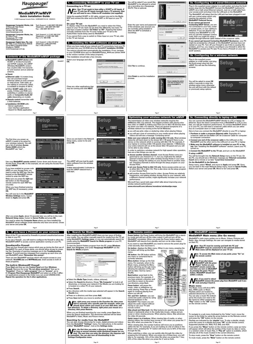
Hauppauge MediaMVP Quick installation guide

Rosewill
Rosewill RSVA-11001 user manual
Dahua Technology
Dahua Technology DH-5208AN-4KL-X-8 user manual
Mitsubishi Electric
Mitsubishi Electric DX-TL5000U series Brochure & specs

Moxa Technologies
Moxa Technologies MxNVR-MO4 user manual

Calibre
Calibre VANTAGE-HD2 user manual
