nilan Compact P Polar EK 6 kW CTS 700 User manual

USER MANUAL
CTS700 TOUCH BY NILAN
Compact P / Compact P Polar (English)
Version 2.40 - 23.05.2019

TABLE OF CONTENTS
Safety
Important information......................................................................................................................................................................................................................................................4
Power supply................................................................................................................................................................................................................................................................... 4
Heat pump domestic hot water ................................................................................................................................................................................................................. 4
Disposal............................................................................................................................................................................................................................................................................................. 4
Ventilation unit............................................................................................................................................................................................................................................................. 4
Heatpump .......................................................................................................................................................................................................................................................................... 4
Quickguide
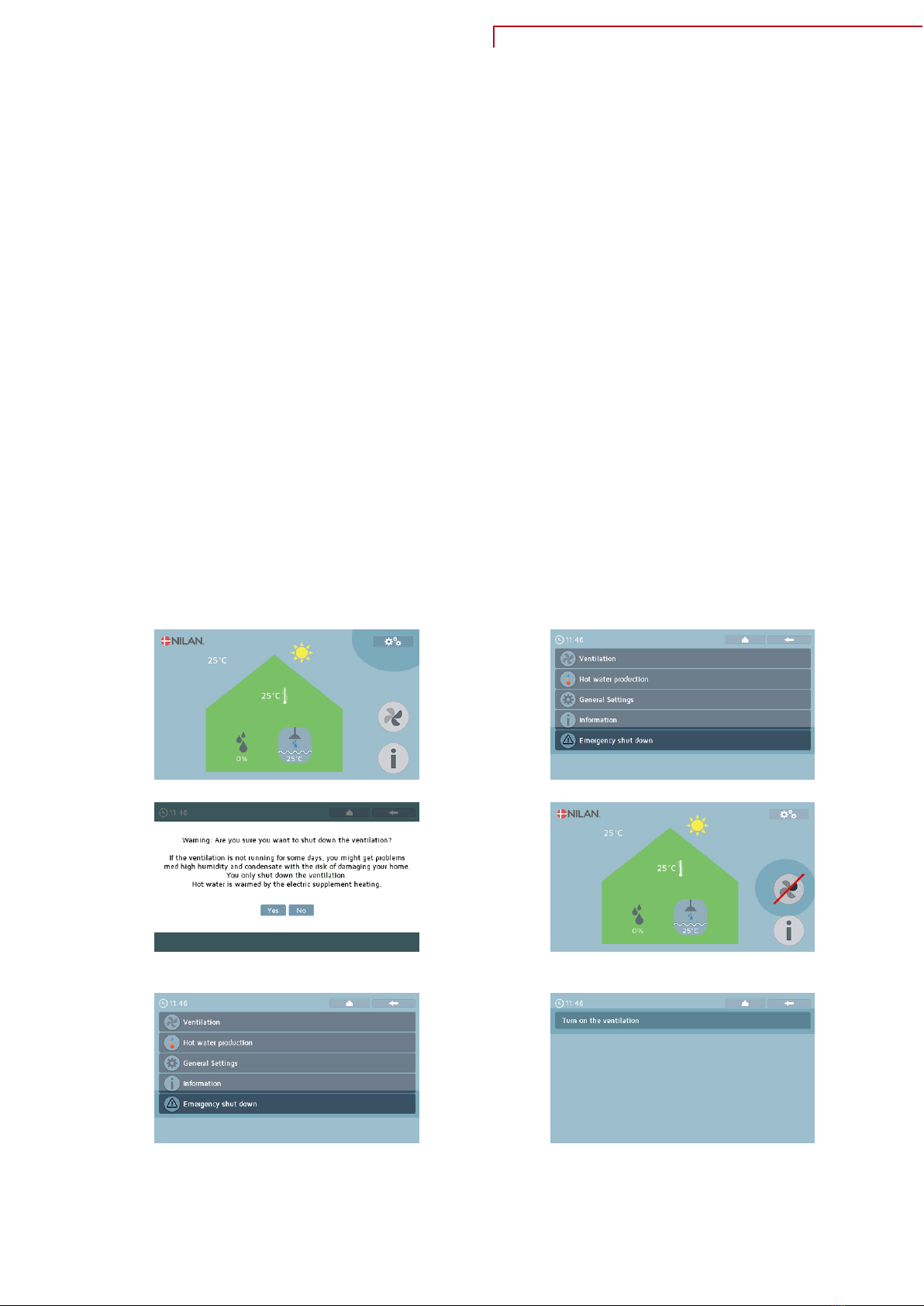
Safety switch...............................................................................................................................................................................................................................................................................5
Emergency stop ventilation .......................................................................................................................................................................................................................... 5
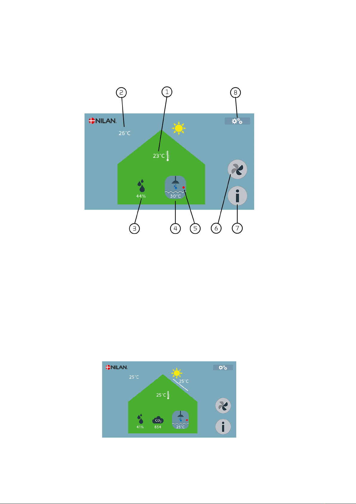
The control panel.................................................................................................................................................................................................................................................................... 6
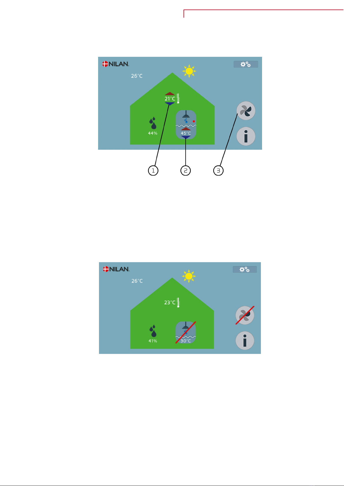
Front page controls.................................................................................................................................................................................................................................................. 6
Front page setting options ..............................................................................................................................................................................................................................7
Information........................................................................................................................................................................................................................................................................8
Warnings and alarms.............................................................................................................................................................................................................................................. 9
Settings menu overview................................................................................................................................................................................................................................. 10
User and installer rights .................................................................................................................................................................................................................................11
Service and Maintanance
Maintenance.............................................................................................................................................................................................................................................................................12
Regular maintenance ........................................................................................................................................................................................................................................ 12
External cleaning ....................................................................................................................................................................................................................................................12
Changing the filters............................................................................................................................................................................................................................................. 12
Illustration of filter change ......................................................................................................................................................................................................................... 13
Water trap ......................................................................................................................................................................................................................................................................14
Safety valves ..............................................................................................................................................................................................................................................................14
Service............................................................................................................................................................................................................................................................................................ 15
Annual service .......................................................................................................................................................................................................................................................... 15
Visual inspection......................................................................................................................................................................................................................................................15
Checking the sacrificial anode .................................................................................................................................................................................................................15
Checking the safety valve.............................................................................................................................................................................................................................15
Internal cleaning ..................................................................................................................................................................................................................................................... 15
Check the air intake and outlet .............................................................................................................................................................................................................. 15
Check ventilation ducts .................................................................................................................................................................................................................................. 16
The heat pump .......................................................................................................................................................................................................................................................... 16
User settings
Ventilation.................................................................................................................................................................................................................................................................................. 17
Filter settings .............................................................................................................................................................................................................................................................17
Operating mode ....................................................................................................................................................................................................................................................... 18
Humidity control .....................................................................................................................................................................................................................................................19
Settings active cooling......................................................................................................................................................................................................................................20
Ventilation at times of low outdoor air temperature ....................................................................................................................................................22
CO 2 control ..................................................................................................................................................................................................................................................................23
Reading off temperatures............................................................................................................................................................................................................................ 24
Domestic hot water.......................................................................................................................................................................................................................................................... 25
DHW standby function ..................................................................................................................................................................................................................................... 25
DHW settings domestic hot water production ...................................................................................................................................................................... 26
DHW anti-legionella..............................................................................................................................................................................................................................................27
DHW reading of temperatures ................................................................................................................................................................................................................27
General settings................................................................................................................................................................................................................................................................... 28
Display settings ....................................................................................................................................................................................................................................................... 28
Week program............................................................................................................................................................................................................................................................ 29
Information................................................................................................................................................................................................................................................................................30
Event log........................................................................................................................................................................................................................................................................... 30
Read data for ventilation and domestic hot water............................................................................................................................................................31
2

Troubleshooting
Alarm lists................................................................................................................................................................................................................................................................................... 33
Alarm list, ventilation and domestic hot water..................................................................................................................................................................... 33
Emergency operation.....................................................................................................................................................................................................................................................35
Emergency operation domestic hot water.................................................................................................................................................................................35
Technical data
Ecodesign data....................................................................................................................................................................................................................................................................... 36
Hot water production......................................................................................................................................................................................................................................... 36
CE declaration.........................................................................................................................................................................................................................................................................37
Compact P / Compact P Polar....................................................................................................................................................................................................................37
Compact P / Compact P Polar (English) BY NILAN
3

Safety
Important information
Power supply
CAUTION
Always disconnect the power supply to the unit if an error occurs that cannot be rectified via
the control panel.
CAUTION
If an error occurs on electrically conductive parts of the unit, always contact an authorised
electrician to rectify the error.
CAUTION
Always disconnect the power supply to the unit before opening the unit doors, for instance for
installation, inspection, cleaning and filter change.
Heat pump domestic hot water
CAUTION
Avoid direct contact with the heating system pipes in the heat pump as they can get very hot.
CAUTION
To protect the heat pump against damage, it is fitted with the following safety equipment:
• Electronic temperature monitoring
The heat pump must undergo suitable service inspections under applicable legislation and regulations
to keep it in good condition and in compliance with safety and environmental requirements.
Responsibility for maintenance of the heat pump rests with the owner/user.
Disposal
Ventilation unit
Nilan’s units consist mainly of recyclable materials. They must, therefore, not be
mixed with household waste, but must be delivered to your local recycling center
for disposal.
Heatpump
Concerning disposal of units with heat pumps, it is important to contact the local
authorities for information about correct handling of these. The heatpump
contains the refrigerant R134a, which is harmful to the environment if not
handled correctly.
4

Quickguide
Safety switch
Emergency stop ventilation
If the ventilation has been stopped for a lengthy period, condensation will occur in the duct system.
This occurs when the warm air in the dwelling penetrates into the cool ducts. This presents the risk that
the water will drip out of the ceiling valves, damaging floors and furniture.
To avoid this, the user is not directly permitted to turn off the ventilation. However in emergency
situations, where the user is asked to go indoors, close windows and doors and turn off ventilation
systems, this must still be possible.
The user may then press the emergency stop in the settings menu:
A warning will appear before the ventilation can be turned off:
Warning: Are you sure you wish to turn off the ventilation?
If the ventilation is not running, you may get problems with high air humidity and condensation in the
ventilation ducts, and a risk that your home may be damaged.
You are only turning off the ventilation. Domestic hot water will be heated by the supplementary
electric heating, if activated.
1. Press the settings icon. 2. Press "Emergency stop ventilation".
3. A warning will appear, but press yes. 4. A red line through the ventilation icon will appear on the display,
indicating that the ventilation has been turned off .
5. When the danger has passed and the ventilation can be used again, press
"Emergency Stop Ventilation" once more. 6. Press "Turn on ventilation again".
Compact P / Compact P Polar (English) BY NILAN
5

The control panel
Front page controls
The front page of the touch panel contains the setting options and the information the user needs most
frequently.
1. Displays the current room temperature in the house, measured via the extract air or via an external
temperature sensor
2. Displays the current outdoor temperature measured in the outdoor air intake
3. Displays the current air humidity measured in the dwelling
4. Displays the current temperature in the hot water tank
5. Displays whether supplementary electric heating in the hot water tank is active
6. Fan speed level: The number of dark segments indicates the desired fan speed level.
7. Information button: Press this to see the unit's current operating status
8. Access to the settings menu, where several settings options are available
If the unit is equipped with a CO2sensor, the CO2level in the building will also be displayed on the front
page, and if a solar panel is installed, the panel temperature will also be displayed.
6

Front page setting options
The settings which the user needs in daily use, can be changed on the front page of the touch-panel.
1. By touching the current room temperature, the wanted room temperature is shown. You can change
the wanted room temperature by touching the red or blue arrow.
2. By touching the current hot water temperature, the wanted hot water temperature is shown. You
can change the temperature in the domestic hot water tank by touching the red or blue arrow.
3. The number of dark segments shows at which ventilation level you want the unit to run. There are
four levels and the level is changed by touching the icon.
If the unit or functions are turned off, a red line will cross the functions, which are off.
Compact P / Compact P Polar (English) BY NILAN
7

Information
By touching the information button, you get an overview about the actual operation state of the unit.
8

Warnings and alarms
If a fault occurs in the unit's operation, a warning or an alarm will be shown.
A warning is a yellow button, which advises that something needs attention, e.g. that
filters or sacrificial anodes need replacing.
The unit operates normally.
The alarm is a red button which denotes that there is something seriously wrong with
the unit, and in most cases this will require the attendance of a technician.
The unit stops operating.
Pressing on the icon will bring up a description of the warning or alarm. The warning or alarm can be
reset by pressing Approve.
Compact P / Compact P Polar (English) BY NILAN
9

Settings menu overview
The settings menu is arranged for clarity and ease of navigation.
Ventilation:This is where all the settings for the ventilation of the dwelling are made.
Domestic hot water production: This is where all the settings for the domestic hot water production are
made.
General settings: This is where settings are made concerning both the ventilation and the domestic hot
water production, and also the service settings.
Information: Here you can see the event log together with the current settings for the entire unit.
Emergency stop ventilation: Preferably, the ventilation system should not be turned off. Turned off
ventilation can cause problems with condensate in the ducts and the unit. However, in emergency
situations it is possible to turn off the ventilation via the emergency stop.
10

User and installer rights
In the setting menu both user, installer and factory settings are shown.
• Settings without any lock can be set by all
•Settings with a white lock can only be set by installers
• Settings with a red lock can only be set by Nilan
The reason why some settings are locked for the user, is because it requires a certain amount of
knowledge about how the unit works in order to change these settings, and if they are set wrongly the
unit does not work properly and can be damaged.
Compact P / Compact P Polar (English) BY NILAN
11

Service and Maintanance
Maintenance
Regular maintenance
Your Nilan ventilation unit will last for many years if it is correctly maintained. Correct maintenance
will also ensure that the unit runs optimally at all times with low energy consumption.
In the following we point out the regular maintenance which you can perform yourself and the annual
service which should be carried out by a professional.
External cleaning
The ventilation unit
The outside of the unit can be cleaned with a mild soap solution.
The ceiling valves
Over time a ring may develop round the inlet valves. This is a natural process and is due to dust in the
room air, not to defective filters or failure to change filters.
As very few painted ceilings are washable, you are recommended to vacuum round the valve and then
wipe the area with a damp cloth.
It is a good idea to dismantle and clean the valves when necessary. The valves have been set by the
installer for a specific airflow, so it is important not to rotate them, as this will change the setting and
unbalance the ventilation system.
Changing the filters.
The filters are there to protect the fans and heat exchanger by preventing them from being coated by
dust and dirt.
For optimum operation it is important to change the filters before they become clogged. In normal
operation, G4 filters from Nilan should be changed every three months. In newbuild, it is recommended
that the filters are changed when the house is first occupied, as they may be clogged with building dust.
If the filters are not changed regularly, this will hamper ventilation, reducing the indoor air quality,
using more power than necessary, and producing insufficient domestic hot water.
12

Illustration of filter change
1. Set the unit to standby on the control panel in the
"Filter settings" menu under Ventilation before opening
the door.
2. Turn the thumb screws in the door at the top right of
the unit and open the door.
3. Remove the two filters from the unit. 4. It is a good idea to vacuum the filter chamber to
remove any dirt which has collected there.
5. Remove the filter pad from the filter frame. 6. Place the new filter pad with its smooth side down in
the filter frame.
7. Carefully fix the filter pad in place in the filter frame,
pushing it well out into the sides. Replace the filter in the
unit with the filter pad facing upwards.
8. Reset the alarm:
Reset the alarm on the control panel in the "Filter
settings" menu under Ventilation.
Compact P / Compact P Polar (English) BY NILAN
13

Water trap
If the water trap in the condensate outlet dries out, air will blow into the unit. This will prevent the
condensate water from draining away. Instead it will accumulate in the condensate tray. When there is
no space left in the condensate tray, it will spill over, possibly causing water damage on the floor.
ATTENTION
The water trap must be checked at regular intervals and filled with water. This is done by filling
the condensate tray with water and checking that it runs out.
Safety valves
The safety valve for the domestic hot water is prominently connected to the drain by the installer. It is
important to check regularly that it is not dripping from the valve.
If it is dripping, contact a plumber to remedy the matter.
14

Service
Annual service
It is important to perform an annual service on the unit to ensure it will continue to perform optimally
with low energy consumption and long service life.
You are recommended to take out a service agreement with the installer, as certain elements of the
service require an authorised technician.
Visual inspection
You are recommended to carry out a visual inspection of the whole unit.
Check that there are no sweating pipes to cause condensation and damage the substrate on which the
unit stands.
Check that there are no cracks in hoses and pipes and no leaks in the heat pump and hot water tank.
Check that there are no damaging accumulations of dirt in the unit.
Checking the sacrificial anode
An electrically monitored anode has been mounted for protecting the hot water tank. When it is time to
change the anode, a warning will appear on the control panel display.
Check the sacrificial anode to ensure that the electrical monitoring is undamaged.
Checking the safety valve
The safety valve for the domestic hot water should have an annual function check to ensure it is
functional at all times.
The function check must be carried out by a trained plumber.
Internal cleaning
For hygienic reasons, it is important that the unit undergoes annual internal cleaning. This will prevent
the formation of fungus and bacteria which impair the internal air quality.
• Wipe down the internal plate parts and pipes with a damp cloth and a mild soap solution.
• Check and clean the evaporator coil.
• Check and clean the counterflow heat exchanger. If necessary, it may be removed and rinsed with a
shower head.
• Clean the condensate trays with a damp cloth and a mild soap solution.
• Check the condensate outlet to make sure the water can exit freely.
Check the air intake and outlet
It is important for operation of the unit that air can freely move through the air intake and outlet.
If roof stacks have been fitted to the air intake and outlet, check that they are not blocked with birds'
nests, leaves or other dirt which can hamper air passage.
If, instead of roof stacks, grilles have been mounted in facades or eaves, check that they are not
clogged with leaves or dirt. Grilles are particularly likely to become clogged.
Compact P / Compact P Polar (English) BY NILAN
15

Check ventilation ducts
It is important for operation of the unit that there is free air passage through the ventilation ducts.
After some years of operation, dirt will attach itself to ventilation ducts or tubes, and accumulations
may lead to higher pressure drop in the ducts, leading to higher power consumption. It is therefore
important to clean out the ducts when too much dirt has collected.
After attending to the inlet and outlet valves, it will be advisable to have them adjusted again, to
ensure optimum operation of the ventilation system.
However, it will not be necessary to clean ducts more than every few years.
The heat pump
The heat pump must be inspected in accordance with applicable laws and regulations, such that it is
kept in good condition and meets safety and environmental requirements.
The installer is obliged to inform the owner/user about applicable laws and regulations.
16

User settings
Ventilation
Filter settings
The filter alarm has a timer which is set at the factory to give 90 days between filter changes.
Supply air filters and extract air filters are set separately. The unit leaves the factory with a G4
standard filter, but an F7 pollen filter can be purchased for the outdoor air. The service life of the two
types of filter differs.
Ventilation
Filter settings
↳Set ventilation to standby Settings:
Standard setting:
Description:
On / Off
Off
Before opening the unit to change the filter, turn off
the ventilation.
If you forget to turn on the ventilation again, it will
automatically restart after 2 hours.
↳Outdoor air filter
↳Filter change warning Settings:
Standard setting:
Description:
None / Digital / Timer
Timer
Settings performed by the installer.
↳Days between filter change Settings:
Standard setting:
Description:
30 ↔180 days
90 days
Number of days between filter changes can be set as
required.
It is important that filters are clean, to give optimum
operation and low power consumption. Dirty filters
reduce production of domestic hot water.
↳Days to next filter change Description: Shows how many days remain to the next filter change.
↳Reset timer Description: Press to reset timer.
NB! This must be done after each filter change.
↳Extract air filter Same settings options as
for the outdoor air filter
Compact P / Compact P Polar (English) BY NILAN
17

Operating mode
It is possible to provide the unit with an input which determines whether it will operate in Auto, Heating
or Cooling.
Ventilation
Operating mode Settings:
Standard setting:
Description:
Auto/ Heating/ Cooling
Auto
Auto : The unit operates in accordance with the set
values.
Heating : The unit operates in accordance with the set
values, but is not set to perform cooling.
Active cooling has been blocked and the bypass
damper will not open.
Cooling : The unit operates in accordance with the set
values, but is not set to perform heating.
Active heating and the after heating element have
been blocked.
With this setting the unit can perform cooling in winter
operation under the correct conditions.
The functions Heating and Cooling override the weekly schedule, and can be used in situations such as
the following:
Heating
A weekly schedule has been made in which the room temperature is lowered between 8.00 and 16.00
during the day, when the residents are at work or school. During the autumn half-term they no longer
wish to lower the daytime temperature as they are at home that week. Instead of cancelling the weekly
schedule, this can be overridden by setting the unit to heating mode. The unit now operates in
accordance with the desired room temperature, which can be set on the front of the touch-panel.
Cooling
A large modern house with extensive south-facing windows can start having overheating problems as
early as March/April, if the sun is shining form a cloudless sky. As the outdoor temperature maybe only
is 8 °C, the unit will be running in winter mode, with a setting which prevents it from cooling. This
limitation can be overridden by setting the unit to cooling mode. The unit will try to cool the indoor air,
if the right conditions are present. Cooling will take place via bypass and at high indoor temperatures
with active cooling via the heat pump.
ATTENTION
The system will automatically change to Auto on the next change in the weekly schedule, is such
is programmed.
18

Humidity control
The unit has a built-in humidity control to control the ventilation relative to the average humidity, in
order to maintain a good relative humidity in the house.
If the average humidity in the house is below a set level (factory setting 30%), it is possible to reduce
the ventilation to avoid further drying of humidity in the house. It will typically only be needed for
shorter periods during the winter.
The humidity control has a further feature that allows increased ventilation if the humidity level gets
high, for example, if you take a bath. It reduces the risk of mold formation in the bathroom, and in most
cases you avoid dew on the mirror in the bathroom.
The humidity control system follows the average air humidity measured over the previous 24 hours. In
this way, the system automatically adapts to summer and winter conditions.
Ventilation
Humidity control
↳Low humidity level Settings:
Standard setting:
Description:
15 ↔45 %
30 %
The humidity control calculates the average air
humidity measured over the previous 24 hours. If the
average air humidity in the extract air falls below this
level, the "Low humidity" function is activated.
↳Fan speed at low humidity Settings:
Standard setting:
Description:
Level 1/ Level 2/ Level 3
Level 1
In case of "Low himidity", the unit changes to the set
fan speed level.
↳Fan speed at high humidity Settings:
Standard setting:
Description:
Level 2/ Level 3/ Level 4
Level 3
In case of "High humidity", e.g. when bathing, the unit
changes to the set fans speed level.
↳Max. time at high humidity (min) Settings:
Standard setting:
Description:
0 ↔180 minutes
60 minutes
The function "High humidity" stops when the actual air
humidity is 3% above average air humidity.
There is a time limit set for how long this function is
allowed to run. If it is set to 0 minutes, the function is
de-activated.
↳Average air humidity Description: This shows the relative humidity in the extract air as
an average over the previous 24 hours.
Prioritisation sequence in the control system:
1. Userprogram 2 and 1 with high priority for ventilation
2. High ventilation in connection with cooling
3. Low ventilation in connection with low outdoor air
temperature
4. Low air humidity
5. High air humidity
6. User program 2
7. User program 1
8. CO 2 level (accessory)
9. Manually set values
10. Week program
Compact P / Compact P Polar (English) BY NILAN
19

Settings active cooling
Depending on architecture, the dwelling may require cooling in the summer. Compact P has an integral
heat pump, primarily used for production of domestic hot water. The heat pump has a reversible
cooling cycle, and in summer is able to cool the supply air, while still producing domestic hot water.
Thus, in principle, this gives "free" domestic hot water heating.
The heat pump is able to cool the supply air by up to 10 °C and, in order to make it as efficient as
possible, it is a good idea to turn up the ventilation when cooling is required.
However, it must be emphasised that it does not function like a conventional air conditioning unit.
Instead, by cooling the supply air, the indoor air is dehumidified, thus giving a pleasant indoor climate
even when indoor temperatures are high.
Ventilation
Active cooling settings
↳Allow active cooling Settings:
Standard setting:
Description:
On / Off
Off
With this it is possible to select or deselect active
cooling via the heat pump.
↳Setpoint active cooling Settings:
Standard setting:
Description:
20 ↔35°C
26°C
This indicates the desired temperature at which active
cooling is to start and stop again when the
temperature falls below.
↳High fan speed when cooling Settings:
Standard setting:
Description:
On / Off
Off
This indicates whether it is wished to raise the
ventilation level when the unit switches to cooling.
NB: The ventilation level is already raised in the case of
bypass cooling and cooling recovery, and not just in the
case of active cooling.
↳Fan speed when cooling Settings:
Standard setting:
Description:
Level 3 / Level 4
Level 3
This indicates at what fan speed level the unit is to run
in cooling operation.
Requires that "High fan speed when cooling" is
activated.
↳Minimum cooling supply temp. (ºC) Settings:
Standard setting:
Description:
5 ↔30°C
5°C
Here the minimum supply air temperature is set for
the unit during cooling mode.
↳Cooling priority to hot water Settings:
Standard setting:
Description:
On / Off
Off
This indicates whether the cooling function is to have a
higher priority than production of domestic hot water*.
*When domestic hot water is needed, the heat pump will run at a higher level, and cannot
simultaneously perform active cooling during that period. However, it will open the bypass damper if
cooling is required.
By choosing cooling to have a higher priority than hot water, the unit will cool the supply air and store
the heat in the hot water tank during that period. The domestic hot water will be heated, but not as
quickly as usual in normal domestic hot water production.
20
Other manuals for Compact P Polar EK 6 kW CTS 700
4
Table of contents
Other nilan Control Unit manuals
Popular Control Unit manuals by other brands

Viega
Viega Easytop XL Series Instructions for use

M-system
M-system R7F4DD-DC16A-H instruction manual

Pioneer
Pioneer CX-961 Service manual

HYDAC FILTER SYSTEMS
HYDAC FILTER SYSTEMS FMM-A-S Series Installation and maintenance instructions

schmersal
schmersal PSC1-C-10 Series installation manual

Lenze
Lenze L-force CANopen EMF2178IB Communications manual