Ningbo Dino-power Machinery DP6388B User manual

Owner sManual
ForprofessionalUseonly
Donotusethisequipmentbeforereadingthismanual!
AirlessSprayer
InternationalModel
NOTE:Thismanualcontainsimportantwarnings
andinstructions.Pleasereadandretainfor
reference
DP6388B
Originalinstruction
NingboDino-powerMachineryCo.,Ltd www.dpairless.com
#606GuangboLijingCenter,TiantongS.Rd,YinzhouDistrict,Ningbo,China

TableofContents
SafetyPrecautions…………………………………..2
GeneralDescription……...………………………....4
TechnicalParameter………………………………...4
Operation…………………………..………...……....4
Setup……………………...……………….……........4
PreparingtoPaint………………………...…….......5
Painting….........……………………....………........5
ElectronicPressureControlIndicators….…….....5
PressureReliefProcedure………………….…......6
Spraying………………….……………………………6
SprayingTechnique…………............………….....6
Practice…………………………….........…….........7
ShutdownandCleaning………………………...…..7
Troubleshooting……………………………..……….8
PartsListings…………………………….…………..10
MainAssembly…………………………………...10
MotorAssembly…………………………...….....11
GearBoxAssembly…………………..………....12
SuctionSetAssembly………………….………..12
StandAssembly……………...………..………...12
FluidSectionAssembly………………….…......13
TipSelection……………………………………...14
SelectingTipHoseSize…………...…....…….......14
ChoosingTheCorrectTip…......………...............14
TipHoseSize…………….....………....……….......14
Fanwidth………..……………………….………......14
UnderstandingTipNumber…............……….......14
ReversibleTipSelectionChart............……….....15
SafetyPrecautions
ThismanualContainsInformationthatmustbereadand
understoodbeforeusingtheequipment,Whenyoucometoan
areathathasoneofthefollowingsymbols,payparticular
attentionandmakecertaintoheedthesafeguard.
WARNING
ThisSymbolindicatesapotentialhazardthatmaycause
seriousinjuryorlossoflife.Importantsafetyinformation
willfollow.
CAUTION
Thissymbolindicatesapotentialhazardtoyouortothe
equipment.Importantinformationthattellshowtoprevent
damagetotheequipmentorhowtoavoidcausesofminor
injurieswillfollow.
NOTE:Notesgiveimportantinformationwhichshouldbegivenspecial attention.
NOTE:Notesgiveimportantinformationwhichshould
begivenspecialattention.
WARNING
Airlessunitsdevelopextremelyhighsprayingpressures.
Neverputyourfingers,handsoranyotherpartsofthe
bodyintothesprayjet.
Neverpointthespraygunatyourselforanybodyelse.
Neverusethespraygunwithoutthesafetyguard.
Attention!Dangerofinjurybyinjection!
Incaseofinjurytoskincausedbycoatingmaterialsor
solventsconsultadoctorimmediately.Informthedoctorofthe
typeofcoationgmaterialorcleaningagentwithwhichtheinjury
wascaused.
Theoperatinginstructionsstatethatthefollowingpoints
mustalwaysbeobservedbeforestartingup:
1.Faultyunitsshouldnotbeused.
2.Securespraygunusingthesafetycatchonthetrigger
3.Ensurethattheunitisproperlyearthed.
4.Checkthepermissibleoperatingpressure.
5.Checkallconnectionsforleaks.
Theinstructionsregardingregularcleaningand
maintenanceoftheunitmustbestrictlyobserved.
Beforeanyworkisdoneontheunitorforeverybreakin
workthefollowingrulesmustbeobserved:
1.Releasethepressurefromthespraygunandhose.
2.Securethespraygunusingthesafetycatchonthe
trigger.
3.Turnoffthemotor.
Besafety-conscious!
Alllocalregulationinforcemustbeobserved.
Inordertoensuresafeoperationoftheairlesssystems
thesafetyregulationslistedbelowmustbefollowed:
1.Inordertoavoiddangers,readtheoperatinginstructions
carefullyandfollowtheinstructionslaiddowninthem.
2.Donotusematerialswithflashpointbelow2(7).
3.Theuseofthisunitisprohibitedinworkshopswhichare
coveredundertheexplosionpreventionregulations.
4.Neverspraynearsourcesofignition;e.g.openflames,
cigarettesalsocigarsandpipesaresourcesofignition
-sparks,hotwiresandhotsurfaces,etc.
5.Attention!Dangerofinjurybyinjection!
Neverpointthespraygunatyourselforanyoneelse.
Neverputyourfingersorhandsintothesprayjet.The
veryhighsprayingpressurescancauseveryserious
injuries.Neverusethespraygunwithoutthesafetyguard.
1℃0℉H
WhenInstallingandremovingthetipandduringbreaksin
workthespraygunmustalwaysbesecured,sothatit
cannotbeactivated.
6.Wearrespiratoryequipmentwhenspraying.Theoperator
mustbeprovidedwithaprotectivemask.
Inordertopreventworkrelatedillness,themanufacturers
agentsusedmustbeobservedwhenpreparing,working
withandcleaningtheunit.Protectiveclothing,glovesand
incertaincases,protectiveskincreamarenecessaryto
protecttheskin.
7.Thespraygunandhighpressurehosebetweentheunit
andspraygunmustbeofasufficientstandardforthe
pressureproducedintheunit.
Thepermissibleoperatingpressureforthehigh-pressure
hose,themanufacturerandthedateofmanufacturemustbe
indicatedbyapermanentidentificationmarkingonthe
hose.Furthermore,itmustbeconstructedsothatthe
electricalresistancebetweentheconnectionstotheunit
andthespraygunisequaltoorlessthanonemegohm.
8.Undercertainconditionsthefollowspeedcancausean
electrostaticchargeontheunit.Thiscouldcausesparks
orflamesondischarging.Itis,therefore,importantthat
theunitisalwaysearthedovertheelectricalinstallation.
Thecontactshouldbemadeusingashockproofsocket
earthedinaccordancewiththeregulations.
'
9.Forbiddentouseofelectrostaticatomisingandspraying
equipmentwithmachinesnotspecificallydesignedforthis
equipment,becauseitmayresultinserioushazardsfor
theoperators;
10.Payattentiontohazardsresultingfromcontactwithand/or
breathingoftoxicmaterials,gases,mistsandvapourswhich
maybecreatedbyoperationofthemachine.
11.Beforeinstallationandusage,visuallyinspectionfordamage
onhoseswhichmaybesubjectedtofrictionshouldbedone.
2.

9.Attention!Pleaseobservethefollowingwhenworking
insideandoutside:
NoSolventGassesShouldbecarriedtotheunit.No
solventgassesshouldfromneartheunit.Setuptheunit
ontheoppositesidetotheobjectbeingSprayed.When
sprayingoutdoors,takethewinddirectionintoaccount.
Whenworkingindoorstheremustbesufficientventilation
toensurethatthesolventgassesarecarriedaway.A
minimumdistanceof6.1m(20')mustbeobserved
betweentheunitandobjectbeingsprayed.
10.ExtractionequipmentShouldbeinstalledbytheuserin
accordancewiththelocalregulations.
11.Theobjectsbeingsprayedmustbeearthed.
12.Whencleaningtheunit,solventshouldneverbesprayed
intoacontainerwithonlyasmallopening(bunghole).An
explosivegas/airmixtureislikelytoform.Thecontainer
mustbeearthed.
13.Cleaningtheunit.
Aharshjetshouldneverbeusedtospraytheunit.In
particularahigh-pressurecleanerorhigh-pressuresteam
cleanershouldneverbeused.Thereisadangerthat
waterwillpenetrateintotheunitandcauseashort-circuit.
14.Pullingthetriggercausesarecoilforcetothehandthatis
holdingthespraygun.
Therecoilforceofthespraygunisparticularlypowerful
whenthetiphasbeenremovedandahighpressurehas
beensetontheairlesshigh-pressurepump.Therefore,
whencleaningwithouttipsetthepressurecontrolvalveto
thelowestpressure.
15.Themainsplugshouldonlybedisconnectedfromthe
socketwhenworkisbeingcarriedoutontheelectrical
components.
14.Workorrepairsshouldonlybecarriedoutonelectrical
equipmentbyatrainedelectrician,eveniftheworkis
describedintheoperatinginstructions.Noliabilitywillbe
acceptedforincorrectlyinstalledelectrics.
15.Positioningwhenthegroundisuneven.
Thefrontoftheunitmustpointdownwardsothatthe
machinedoesnotslipaway.
HAZARD:INJECTIONINJURY-Ahighpressurestream
ofpaintproducedbythisequipmentcanpierce
theskinandunderlyingtissues,leadingto
seriousinjuryandpossibleamputation.
DONOTTREATANINJECTIONINJURYASA
SIMPLECUT!Injectioncanleadto
amputation.Seeanphysicianimmediately.
PREVENTION:
Themaximumoperatingrangeoftheunitis221BAR
(3200PSI)fluidpressure.
Neveraimthegunatanypartofthebody.
Neverallowanypartofthebodytocomeincontactwith
streamcreatedbyaleakinthefluidhose.
NeverPutyourhandinfrontofthegun.Gloveswillnot
provideprotectionagainstandinjectioninjury.
ALWAYSlocktheguntrigger,shutthefluidpumpoffand
releaseallpressurebeforeservicing,cleaningthetip
guard,changingtips,orleavingunattended.Pressurewill
notbereleasedbyturningofftheengine.The
PRIME/SPRAYknobmustbeturnedtoPRIMEtorelieve
thepressure.RefertothePRESSURERELIEF
PROCEDUREdescribedinthismanual.
Thetipguardmustalwaysbeinplacewhilespraying.The
tipguardprovidessomeprotectionagainstinjection
injuriesbutismainlyawarningdevice.
ALWAYSremovethespraytipbeforeflushingorcleaning
thesystem.
Thepainthosecandevelopleakfromwear,kinkingand
abuse.Aleakiscapableofinjectingmaterialintotheskin.
Inspectthepainthosebeforeeachuse.
NOTETOPHYSICIAN:
Injectionintotheskinisatraumaticinjury.Itis
importanttotheattheinjurysurgicallyassoonas
possible.DONOTdelaytreatmenttoresearchtoxicity.
Toxicityisaconcernwithsomecoatingsinjected
directlyintothebloodstream.Consultationwitha
plasticsurgeonorreconstructivehandsurgeonmaybe
advisable.
HAZARD:EXPLOSIONORFIRE-Solventandpaintfumes
canexplodeorignite,causingpropertydamage
and/orsevereinjury.
PREVENTION:
Fireextinguishingequipmentmustbepresentandingood
workingorder.
Useonlyconductiveorearthedhighpressurefluidhoses
forairlessapplications,besurethatthegunisearthed
properlythroughhoseconnections.
Thepumpmustbeconnectedtoanearthedobject.Use
thegreenearthingwiretoconnectthepumptoawater
pipe,steelbeam,orotherelectricallyearthedsurface.
Whenflushingequipmentusethelowestpossible
pressure.
HAZARD:EXPLOSIONHAZARDDUETOINCOMPATIBLE
MATERIALS-Maycausepropertydamageor
severeinjury.
PREVENTION:
Donotusebleach.
Donotusehalogenatedhydrocarbonsolventssuchas
methylenechlorideand1,1,1-trichloroethane.Theyare
notcompatiblewithaluminumandmaycausean
explosion.Ifyouareunsureofamaterial'scompatibility
withaluminum,contactyourcoating'ssupplier.
HAZARD:GENERAL-Maycausepropertydamageor
severeinjury.
PREVENTION:
Thishighpressureairlesspumpisdesignedtobeused
withmanufacturerauthorizedpartsonly.Whenusingthis
pumpwithpartsthatdonotcomplywiththeminimum
specificationsandsafetydevicesofthepump
manufacturer,theuserassumesallrisksandliabilities.
Beforeeachuse,checkallhosesforcuts,leaks,abrasion
orbulgingofcover,aswellasdamageormovementof
couplings.Ifyouanyoftheseconditionexist,replacethe
hoseimmediately.Neverrepairapainthose.Replaceit
withanotherearthedhose.
Wearprotectiveeyewear.
Donotsprayonwindydays.
EarthingInstructions
Thisproductmustbeearthed.Intheeventofanelectrical
shortcircuit,earthingreducestheriskofelectricshockby
providinganescapewirefortheelectriccurrent.Thisproduct
isequippedwithacordhavinganearthingwirewithan
appropriateearthingplug.Theplugmustbepluggedintoan
outletthatisproperlyinstalledandearthedinaccordancewith
alllocalcodesandordinances.
DANGER-Improperinstallationoftheearthingplugcan
resultinariskofelectricshock.
Ifrepairorreplacementofthecordorplugisnecessary,donot
connectthegreenearthingwiretoeitherflatbladeterminal.
Thewirewithinsulationhavingagreenoutersurfacewithor
withoutyellowstripesistheearthingwireandmustbe
connectedtotheearthingpin.
Checkwithaqualifiedelectricianorservicemaniftheearthing
instructionsarenotcompletelyunderstood,orifyouarein
doubtastowhethertheproductisproperlyearthed.Donot
modifytheplugprovided.Iftheplugwillnotfittheoutlet,have
theproperoutletinstalledbyaqualifiedelectrician.
3.
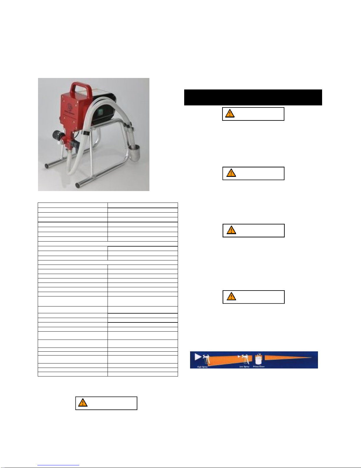
GeneralDescription
Thisairlesssprayerisaprecisionpowertoolusedforspraying
manytypesofmaterials.Readandfollowthisinstruction
manualcarefullyforproperoperatinginstructions,
andsafetyinformation.
TechnicalParameter
Workingpressurerange
0-2800psi(0-19MPa,0-193bar)
Electricmotor 6.0A(openframe,universal)
Operatinghorsepower 1/2 hp 375w
Maximumdelivery(withtip) 0.25gpm(1.0lpm)
PaintHose 1/4inx25ft(6.4mmx7.5m)
MaximumTipholesize 0.015in.(0.38mm)
Weight,sprayeronly 16lb(7.3kg)
Weight,sprayer,hose&gun 19.2lb(8.7kg)
Dimensions(upright):
Length 14.5in(36.8cm)
Width: 12.4in(31.5cm)
Height: 17.9in(45.5cm)
Dimensions(Folded):
Length: 19.3in(49.0cm)
Width: 15.3in(38.9cm)
Height: 29.2in(74.2cm)
PowerCord: 18AWG,3wire,6ft(1.8m)
Fluidinletfitting
3/4in.internalthread(Standardgardenhosethread)
Fluidoutletfitting 1/4NPSMexternalthread
Inletscreen(onsuctiontube) 35mesh(450micro)
Wettedparts,pump&hose
Stainlesssteel,brass,leather,ultra-highmolecular
weightpolyethylene(UHMWPE),carbide,nylon,
aluminum,PVC,polypropylene,fluroelastomer
Wettedparts,gun Aluminum,brass,carbide,nylon,platedsteel,
stainlesssteel,UHMWPE,zinc
Generatorrequirement 1500Wattminimum
Electricalpowerrequirement 230V50Hz,15A1phase
Storagetemperaturerange -3to16(-35to70°0℉° 1℃)
Operatingtemperaturerange 40to115(4to46°℉°℃)
Operation: WARNING
Thisequipmentproducesafluidstreamatextremelyhigh
pressure.Readandunderstandthewarningsinthe
safetyprecautionssectionatthefrontofthismanual
beforeoperatingthisequipment.
Setup
Performthefollowingprocedurebeforeplugginginthepower
cordofanelectricunit.
1.Ensurethatthesuctionsetandthereturnhoseare
attachedandsecure.
2.Usingawrench,attachaminimumof7.5m24.6'x10mm
(1/4”)nylonairlesssprayhosetotheunit.Tighten
securely.
3.attachanairlesssprayguntothesprayhose.Usingtwo
wrenches(oneonthegunandoneonthehose),tighten
securely.
NOTE:Donotattachthetiptothespraygunyet.
Removethetipifitisalreadyattached.
WARNING
Makesureallairlesshosesandspraygunsareelectrically
groundedandratedforatleast228bar(3300psi)fluid
pressure.
4.MakesurethepressurecontrolknobisinitsOFFposition
5.MakesuretheON/OFFswitchisinitsOFFposition.
6.Filltheoilcupwith15g(onetablespoon)ofpistonseal
lubricant(pistonlube).
CAUTION
Neveroperateunitformorethantensecondswithout
fluid.Operatingthisunitwithoutfluidwillcause
unnecessaryweartothepacking.
7.Makesuretheelectricalserviceiscorrectfortheunit.
8.Plugthepowercordintoaproperlygroundedoutletat
least7.6m(25')fromthesprayarea.
CAUTION
Alwaysuseaminimum12gauge,three-wireextensioncord
withagroundedplug.Neverremovethethirdprongoruse
anadapter.
PreparingaNewSprayer
Ifthisunitisnew,itisshippedwithtestfluidinthefluidsection
topreventcorrosionduringshipmentandstorage.Thisfluid
mustbethoroughlycleanedoutofthesystemwithmineral
spiritsbeforeyoubeginspraying.
CAUTION
Alwayskeepthetriggerlockonthesprayguninthe
lockedpositionwhilepreparingthesystem.
1.Placethesuctiontubeintoacontainerofmineralspirits
thathasaflashpointof60140)orabove.
2.Placethereturnhoseintoametalwastecontainer.
3.TurnPressureControlKnoballthewayleft
(counter-clockwise)tominimumpressure.
℃(℉H
4.MovethePRIME/SPRAYvalvedowntothePRIME
position.
5.TurntheunitonbymovingtheON/OFFswitchtotheOn
position.
6.AllowtheSprayertorunfor15-30secondstoflushthe
testfluidoutthroughthereturnhoseandintothewaste
container.
7.TurntheunitoffbymovingtheON/OFFswitchtotheOFF
position.
Thepaintsprayeriscompatiblewiththefollowingwater
solublepaints:phenolaldehydepaintseries-nitrylpaint
seriesalkydpaintseriesepoxyresinpaintseriesoxidized
rubberpaintserieslatexpaintseriesetc.
Maximumallowablepressureforthe
coatingmaterialMPa
()
Maximumallowabletemperatureofthe
coatingmaterial()
℃
Typicalcoatingmaterialflowrate(l/min)
Soundpowerlevel(LWA4mhemisphere)dB(A)
Soundpressurelevel(LpAAirbornenoise
1mawayfromworkingstation)dB(A)
UncertaintydB(A)
Vibrationvalveforsprayinggun(
m/s2)
Uncertainty(
m/s2)
97.9
90
1.5
2.391
0.5
4.
PreparingtoPain
Beforepainting,itisimportanttomakesurethatthefluidinthe
systemiscompatiblewiththepaintthatisgoingtobeused.
NOTE:Incompatiblefluidandpaintmaycausethe
valvestobecomestuckclosed,whichwould
requiredisassemblyandcleaningofthe
sprayer'sfluidsection.
CAUTION
Alwayskeepthetriggerlockonthesprayguninthe
lockedpositionwhilepreparingthesystem.
1.placethesuctiontubeintoacontaineroftheappropriate
solventforthematerialbeingsprayed(referto
recommendationsofthematerialmanufacture).An
exampleoftheappropriatesolventiswaterforlatexpaint.
2.placethereturnhoseintoametalwastecontainer.
3.setthepressuretominimumbyturningthepressure
controlknoballthewayleft(counter-clockwise)to
minimumpressure.
4.movethePRIME/SPRAYvalvedowntothePRIME
position.
5.TruntheunitonbymovingtheON/OFFswitchtotheON
position.
6.Allowthesprayertorunfor15-30secondstoflushtheold
solventoutthroughthereturnhoseandintothemetal
wastecontainer.
7.TurntheunitoffbymovingtheON/OFFswitchtotheOFF
position.
NOTE:Makesurethatthespraygundoesnothavea
tiportipguardinstalled.
8.MovethePRIME/SPRAYvalveuptotheSPRAYposition.
9.Turntheuniton.
10.Unlockthegunbyturningtheguntriggerlocktothe
unlockedposition.
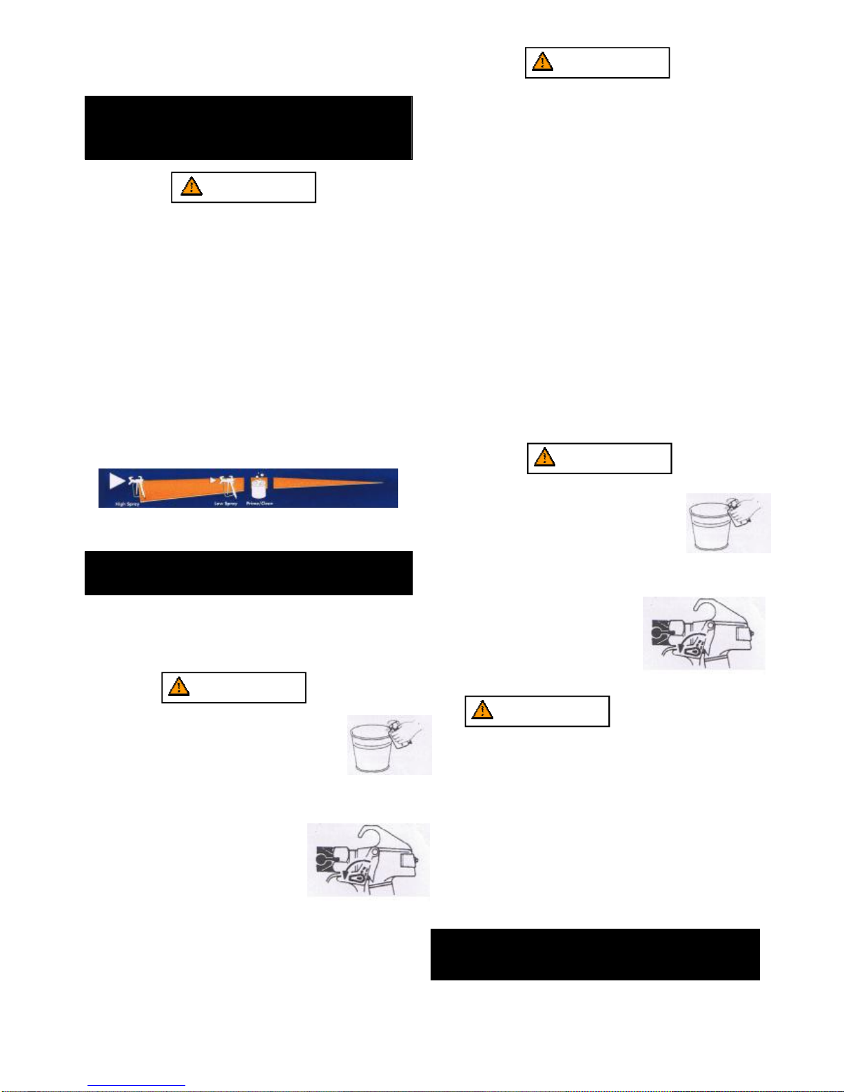
WARNING
Groundthegunbyholdingitagainstthe
edgeofthemetalcontainerwhileflushing.
Failuretodosomayleadtoastatic
electricdischarge,whichmaycauseafire.
11.Triggerthegunintothemetalwaste
containeruntiltheoldsolventisgone
andfreshsolventiscomingoutofthegun.
12.Lockthegunbyturnigthegun
triggerlocktothelockedposition.
13.Setdownthegunandincreasethe
pressurebyturningthepressure
controlknobslowlyclockwiseinto
thehighpressurespray.
14.Checktheentiresystemforleaks.
ifleaksoccur,followthePressure
ReliefProcedure”inthismanualbeforetighteningany
fittingsorhoses
15.Followthe “PressureReliefProcedure”inthismanual
beforechangingfromsolventtopaint.
Triggerlock
inlockedposition
WARNING
Besuretofollowthepressurereliefprocedurewhen
shuttingtheunitdownforanypurpose,including
servicingoradjustinganypartofthespraysystem,
changingorcleaningapraytips,orpreparingforcleanup.
Painting
1.Placethesuctiontubeintoacontainerofpaint.
2.Placethereturnhoseintoametalwastecontainer.
3.Setthepressuretominimumbyturningthepressure
controlknobtotheMinsettinginthelowpressurespray.
4.MovethePRIME/SPRAYvalvedowntothePRIME
position.
5.TurntheunitonbymovingtheON/OFswitchtotheON
position.
6.Allowthesprayertorununtilpaintiscomingthroughthe
returnhoseintothemetalwastecontainer.
7.TurntheunitoffbymovingtheON/OFFswitchtotheOFF
position.
8.Removethereturnhosefromthewastecontainerand
placeitinitsoperatingpositionabovethecontainerofpaint
9.MovethePRIME/SPRAYvalveuptotheSprayposition.
10.Turntheuniton
11.Unlockthegunbyturningtheguntriggerlocktothe
unlockedposition
WARNING
Groundthegunbyholdingitagainstthe
edgeofthemetalcontainerwhileflushing.
Failuretodosomayleadtoastatic
electronicdischarge,whichmaycauseafire.
12.Triggerthegunintothemetalwaste
containeruntilallairandsolventis
flushedfromthesprayhoseandpaintisflowingfreely
fromthegun.
13.Lockthegunbyturningthegun
triggerlocktothelockedposition.
14.Turntheunitoff.
15.Attachtipguardandtiptothegun
asinstructedbythetipguardortip
manuals.
Triggerlock
inlockedposition
WARNING
POSSIBLEINJECTIONHAZARD.Donotspraywithoutthe
tipguardinplace.Nevertriggerthegununlessthetipis
ineitherthesprayortheunclogposition.Alwaysengage
theguntriggerlockbeforeremoving,replacingor
cleaningtip.
16.Turntheuniton
17.Increasethepressurebyturningthepressurecontrol
knobslowlyclockwisetowardthehighpressuresprayand
testthespraypatternonapieceofcardboard.Ajust
thepressurecontrolknobuntilthesprayfromthegunis
completelyatomized.Trytokeepthepressurecontrol
knobatthelowestsettingthatmaintainsgood
atomization.
Note:Turningthepressureuphigherthenneededto
atomizethepaintwillcauseprematuretipwear
andadditionaloverspray
5.

PressureReliefProcedure
WARNING
Besuretofollowthepressurereliefprocedurewhen
shuttingtheunitdownforanypurpose,including
servicingoradjustinganypartofthespraysystem,
changingorcleaningspraytips,orpreparingforcleanup.
1.Lockthegunbyturningthegun
triggerlocktothelockposition.
2.Turntheunitoffbymovingthe
ON/OFFswitchtotheOFFposition.
3.Turnthepressurecontrolknob
counterclockwisetoitsOFFposition
4.Unlockthegunbyturningthegun
triggerlocktotheunlockedposition
5.Holdthemetalpartofthegunfirmlyto
thesideofametalcontainertoground
thegunandavoidabuildupofstatic
electricity.
6.Triggertheguntoremoveany
pressurethatmaystillbeinthehose
7.Lockthegunbyturningtheguntriggerlocktothelocked
position.
8.MovethePRIME/SPRAYvalvedowntothePRIME
position.
Triggerlock
inlockedposition
Spraying WARNING
POSSIBLEINJECTIONHAZARD.Donotspraywithoutthe
tipguardinplace.Nevertriggerthegununlessthetipis
ineitherthesprayortheunclogpostion,Alwaysengage
theguntriggerlockbeforeremoving,replacing,or
cleaningtip.
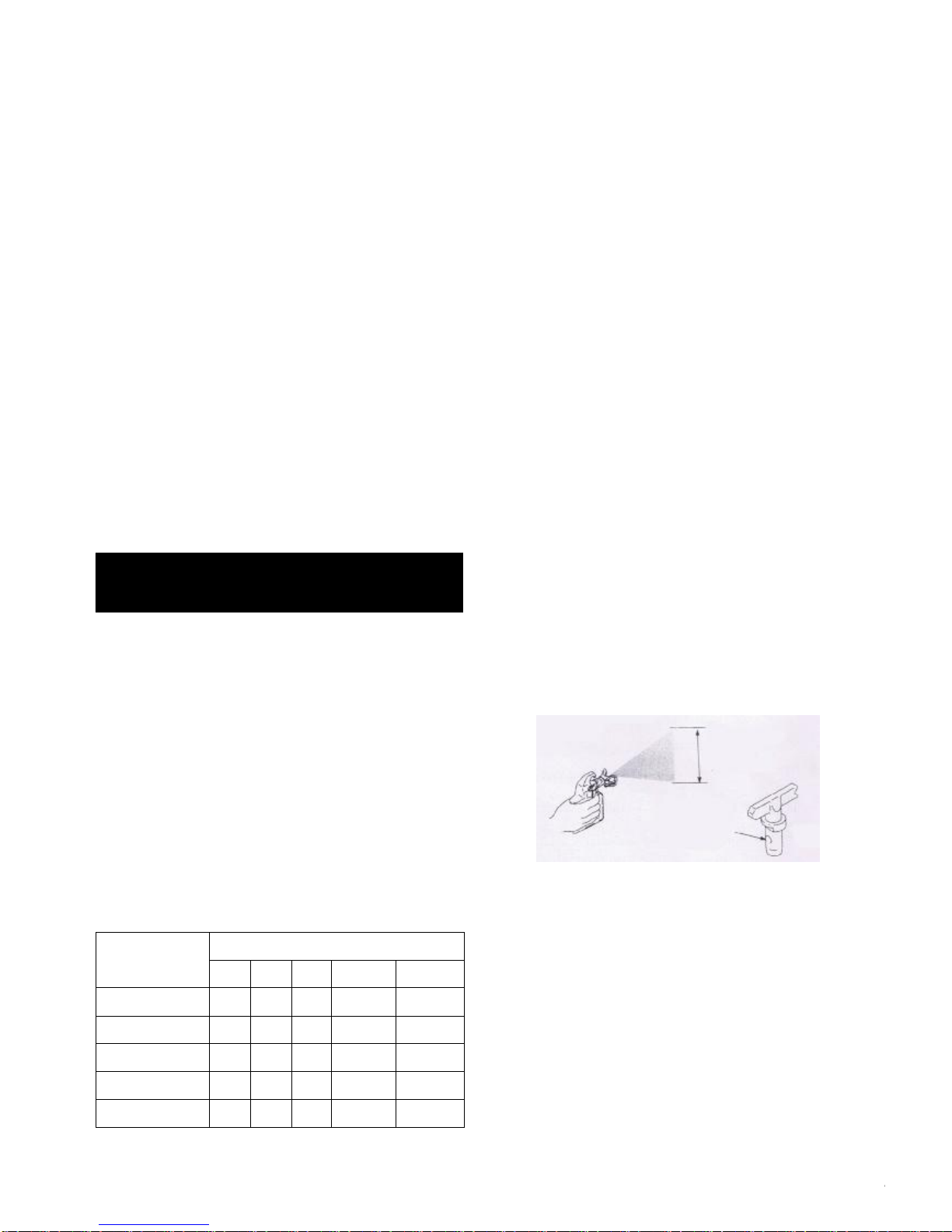
SprayingTechnique
Thefollowingtechniques,iffollowed,willassureprofessional
paintingresults.
Holdthegunperpendiculartothesurfaceandalwaysatequal
distancefromthesurface.Dependingonthetypeofmaterial,
surface,ordesiredspraypattern,thegunshouldbeheldata
distanceof30to50cm(12to14inches)
Movetheguneitheracrossorupanddownthesurfaceata
steadyrate.Movingthegunataconsistantspeedconserves
materialandprovidesevencoverage.Thecorrectsprayingspeed
allowsafull,wetcoatofpainttobeappliedwithoutrunsorsags.
Holdingthegunclosertothesurfacedepositsmorepainton
thesurfaceandproducesanarrowspraypatern..Holding
thegunfartherfromthesurfaceproducesathinnercoatand
widespraypattern.Ifruns,sags,orexcessivepaintoccur,
changetoaspraytipwithasmallerorifice.Ifthereisan
insufficientamountofpaintonthesurfaceoryoudesireto
sprayfaster,alargerorificetipshouldbeselected.
Maintainuniformspraystrokeaction,Sprayalternatelyfrom
lefttorightandrighttoleft.Beginmovementofthegunbefore
thetriggerispulled.
Avoidarcingorholdingthegunatanangle,Thiswillresultin
anunevenfinish.
Start
stroke
Pull
trigger
Release
trigger
End
stroke
Offspray
Toothick
Arcing Gunatangle
Properlapping(overlapofspraypattern)isessentialtoan
evenfinish.Lapeachstroke.Ifyouaresprayinghorizontally,
aimatthebottomedgeoftheprecedingstroke,soastolap
thepreviouspatternby50%.
Overlapedges
1st
pass 2st
pass 3st
pass 4st
pass 5st
pass
Forcornersandedges,splitthe
centerofthespraypatternonthe
corneroredgeandspray
verticallysothatbothadjoing
sectionsreceiveapproximately
evenamountsofpaint.
Whensprayingwithashield,holditfirmlyagainstthesurface.
Anglethespraygunslightlyawayfromtheshieldandtoward
thesurfaceThiswillpreventpaintfrombeingforcedunderneath.
Shrubsnexttohousedshouldbetiedbackandcoveredwitha
canvascloth.Theclothshouldberemovedassoonaspossible.
ourgunextensionsareextremelyhelpfulinthesesituations.
Nearbyobjectssuchasautomobiles,outdoorfurniture,etc.
shouldbemovedorcoveredwheneverinthevicinityofa
sprayjob.Becarefulofanyothersurroundingobjectsthat
couldbedamagedbyoverspray.
6.
PRACTICE
1.Besurethatthepainthoseisfreeofkindsandclearof
objectswithsharpcuttingedges.
2.Turnthepressurecontrolknobcounterclockwisetoitsto
itslowestsetting.
3.TurnthePRIME/SPRAYvalveuptoitsSPRAYposition.
4.Turnthepressurecontrolknobclockwisetoitshighest
setting.Thepainthoseshouldstiffenaspaintbeginsto
flowthroughit.
5.Unlocktheguntriggerlock.
6.Triggerthesprayguntobleedairoutofthehose.
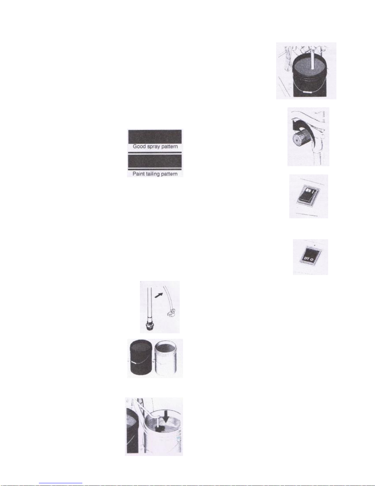
7.Whenpaintreachesthespraytip,sprayatestareato
checkthespraypattern.
Usethelowestpressuresetting
necessarytogetagoodspray
pattern,Ifthepressureissettoo
high,thespraypatternwillbetoo
light.Ifthepressureissettoo
low,tailingwillappearorthe
paintwillspatteroutingobs
ratherthaninafinespray.
ShutdownandCleaning
11.TurnpowerswitchOFF.
1.PressureControlKnobsSettings
2.Removetipandguardassemblyfromgunand
placeinflushingfluid.
3.Liftsuctiontubeandprimetubefrompaintpail
Letthemdrainintopaintpailforawhile.
4.Separateprimetube(smaller)
fromsuctiontube(larger)
5.Placeemptywasteand
waterorsolventpails
sidebyside.
6.Placeprimetubeinwaste
pail.
7.Submergesuctiontubein
waterorflushingsolvent.
8.Turnpressurecontrolknobto
thePRIME/CLEANsetting.
9.TurnthepowerswitchON.
10.Flushuntilapproximately1/3oftheflushing
fluidisemptiedfromthepail.
Whenstoringthepaintstationfor16hoursormore,a
thoroughcleaningisrecommended:
1.shutdownpaintsprayer
2.thoroughlycleanpaintsprayerandstationaccording
instruction;
3.besurethatmachineandtubesareclearanywateror
fluidasthesemayfreeze;
4.Coilhighpressurehoseandstoreonbackoftoolwith
hookandloopstraps;
5.Storefiltersprayinggun,andsprayerinplasticbag
andseal;
7.

Troubleshooting
Problem Cause Solution
Theunitwillnotrun
1.Theunitisnotpluggedin
2.Trippedbreaker
3.Thepressureissettoolow(pressure
controlknobsetatminimumsetting
doesnotsupplypowertounit)
4.Faultyorloosewiring.
5.Excessivemotortemperature.
6.ON/OFFswitchisdefective.
1.Plugtheunitin
2.Resetthebreaker.
3.Turnthepressurecontrolknob
clockwisetsupplypowertotheunit
andincreasethepressuresetting.
4.Inspectortaketoaauthorizedservice
center.
5.Allowmotortocool.
6.ReplacetheON/OFFswitch.
Theunitwillnotprime.
1.ThePRIME/SPRAYvalveisinthe
SPRAYposition
2.Airleakinthepositiontube/suctionset.
3.Thesiphontubefilterand/orinlet
screenisclogged.
4.Thesiphontube/suctionsetisclogged.
1.RotatethePRIME/SPRAYvalve
clockwisetothePRIMEposition.
2.Checkthesiphontube/suctionset.
Connectionandtightenorre-tape
theconnectionwithTeflontape.
3.Removetheinletscreenandclean.
Removethesiphontube/suctionset
andclearn.
Theunitwillnotbuildor
maintainpressure
1.Thespraytipisworn.
2.theSpraytipistoolarge
3.Thepressurecontrolknobisnotset
properly
4.Thepumpfilter,gunfilter,orinlet
screenisclogged.
5.Materialflowsformthereturnhose
whenthePRIME/SPRAYvalveisin
theSPRAYposition.
6.Thereisexternalfluidleak.
7.Airleakinthesiphontube/suction
set.
8.Thereisaninternalfluidsectionleak
(packingsarewornand/ordirty,valve
ballsareworn).
9.Wornvalveseats.
10.Motorpowerbutfailstorotate.
1.Replacethespraytipfollowingthe
instructionthatcamewiththespray
gun.
2.Replacethespraytipwithatipthat
hasasmallerorficefollowingthe
instructionsthatcamewiththespray
gun.
3.Turnthepressurecontrolknob
clockwisetoincreasethepressure
setting.
4.Removethepumpfilterselement
andclean.Removethegunfilterand
clean.Removetheinletscreenand
clean.
5.CleanorreplacethePRIME/SPRAY
valve.
6.Checkthesiphontube/suctionset
connectionandtightenorre-tapethe
conncetionwithTeflonTape.
7.Checkforexternalleaksatall
connections.Tightenconnections,
ifnecessary.
8.Cleanthevalvesandservicethe
fluidsection.
9.Reverseorreplancethevalveseats.
10.Takeunittoauthorizedservice
center.
Fluidleakageattheupper
endofthefluidsection. 1.Theupperpackingsareworn.
2.Thepistonrodisworn. 1.Repackthepumpfollowingthis
manual.
2.Replacethepistonrod.
8.

Troubleshooting
Problem Cause Solution
Excessivesurgeatthe
spraygun. 1.Wrongtypeofairlesssprayhose.
2.TheSpraytipwornortoolarge.
3.Excessivepressure.
1.Replacehosewithaminimumof5m
(50”)X10mm(1/4”)groundtextiled
braidairlesspaintsprayhose.
2.Replacethespraytipfollowingthe
instructionsthatcamewiththespray
gun.
3.Rotatethepressurecontrolknob
counterclockwisetodecreasespray
pressure.
Poorspraypattern. 1.Thespraytipistoolargeforthe
materialbeingused.
2.Incorrectpressuresetting.
3.Thematerialbeingsprayedistoo
viscous.
1.Replacethespraytipwithanewor
smallerspraytipfollingtheinstructions
thatcamewiththespraygun.
2.Rotatethepressurecontrolknobto
adjustthepressureforaproperspray
patter.
3.Addsolventtothematerialaccording
tothemanufacturesrecommendations.
Theunitlackspower.
1.Thepressureadjustmentistoolow.
2.Impropervoltagesupply.
1.Rotatethepressurecontrolknob
clockwisetoincreasethepressure
setting.
2.Connecttheinputvoltagetotheproper
voltagefortheunit.
9.

10.
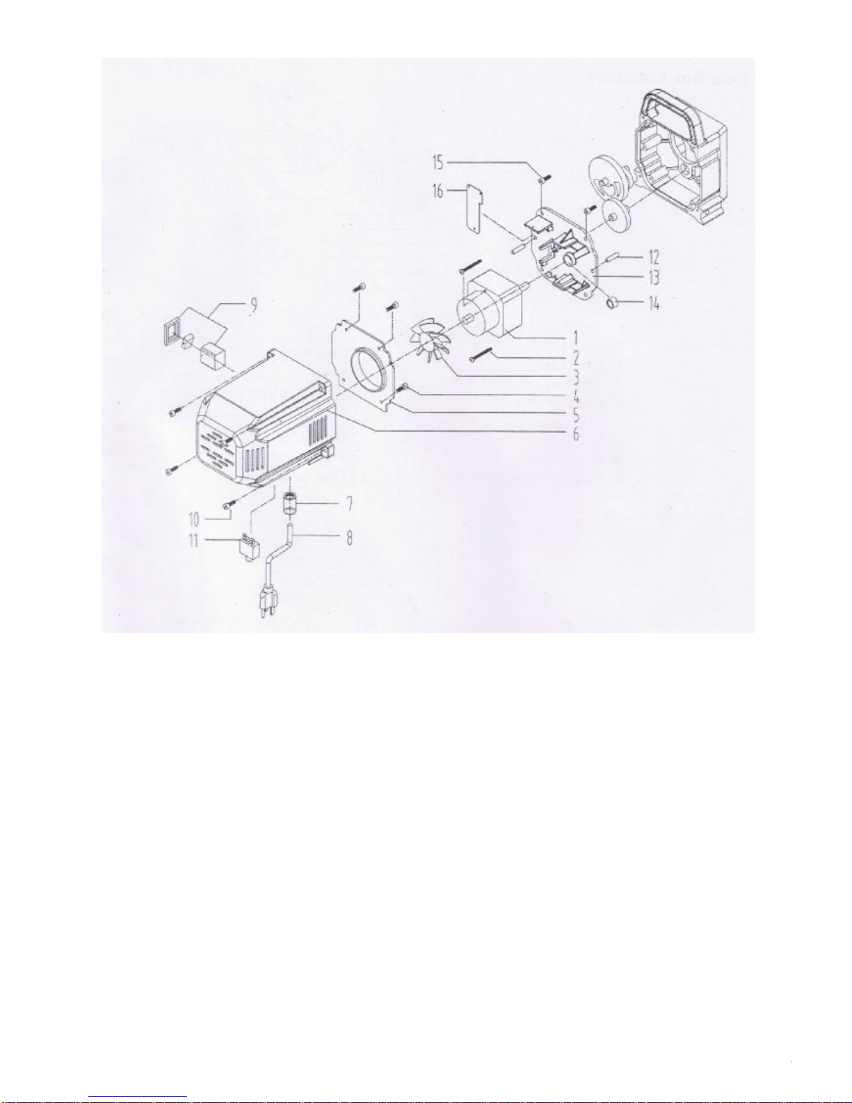
1.Motor.....................................
2.Screw....................................
3.Motorfan...............................
4.Screw....................................
5.Gasket..................................
6.Motorcoverlabels..................
7.Strainrelief............................
8.Powercord............................
MotorAssembly
MotorAssembly
9.ON/OFFswitch.......................
10.Screw....................................
11.Circuitbreaker........................
12.Pin........................................
13.Motorholder...........................
14.Couperoring..........................
15.Screw....................................
16.Electricmainboard.................
1
2
1
4
1
1
1
1
1
4
1
2
1
1
4
1
11.

GearBoxAssembly
GearBoxAssembly
1.Coverlaber..............................
2.Screw......................................
3.Frontcoverw/label...................
4.Rod.........................................
5.Rodcoupero-ring.....................
6.Pumphousing..........................
7.Crankshaft/gearassembly.........
........................
..............................
..................
................................
.......................
................................
........................
8.Gearwrap
9.Wrap
10.2ndstagegear
11.Pin
12.Gearwrap
13.Pin
14.Gearwrap
1
1
1
1
2
2
1
1
8
1
1
1
1
1
5
3
1
2
4
SuctionSetAssembly
SuctionSetAssembly
1.Returntubeassembly..............
2.RetainingClip.........................
3.Siphonhose...........................
4.Inletscreen............................
5.Clip........................................
1
1
1
1
1
StandAssembly
1.Leg........................................
2.Screw....................................
3.Cordwrap..............................
4.Nut........................................
5.Materwasher..........................
6.Dripcup.................................
7.Dripcup2...............................
StandAssembly
2
2
2
2
2
2
2
321
4
56
7
12.

FluidSectionAssembly
FluidSectionAssembly
1.Fluidsection..........................
2.Piston...................................
3.PistonwrapA.........................
4.O-ring...................................
5.PistonwrapB.........................
6.O-ring...................................
7.O-ring...................................
8.Lvasher.................................
9.Alloyslice..............................
10.Ball.......................................
1
1
1
1
1
1
1
1
1
1
11.Rocl.......................................
12.Spring....................................
13.Coupler..................................
14.O-ring....................................
15.Cover.....................................
16.O-ring....................................
17.Pressurerocl..........................
18.O-ring....................................
19.Switch....................................
20.Plasticcover...........................
1
1
1
1
1
2
1
1
1
1
13.
22.Coupler……………..........…..
23.Spring………………………….
24.HolderHNeedle……………...
25.Shell…………………………….
26.Spring…………………………..
27.Ball……………………………...
28.AllgSlice……………………….
29.O-ring……………………....….
30.Connector……………………..
31.O-ring,Viton…………………..
32.O-ring,Teflon………………….
33.Gasket………………………….
34.ValveHousing………………...
35.ValveStem………………….....
36.Spring…………………….…….
37.ValveRetainer………………...
38.Cambase……………………...
39.ValveHandle……………….….
40.Pin……………………………….
41.GroovePin………………….….
42.Fitting……………………….…..
1
1
1
1
1
1
1
1
1
1
1
1
1
1
1
1
1
1
1
1
1
NOTE:WhenUsing “HOT”solvents,replaceViton
O-ring(item32)withoptionalTeflono-ring
installwitho-ringtool
TipSelection
SelectingTipHoleSize
ReversibletipSelectionChart
Tipscomeinavarietyofholesizesforsprayinga
rangeoffluids.Yoursprayerincludesan0.015in
(0.38mm)tipforuseinmostsprayingapplications.
Usethefollowingtabletodeterminetherangeof
recommendedtipholesizesforeachfluidtype.If
youneedatipotherthantheonesupplied,seethe
onpage15.
HINTS:
Asyouspray,thetipwearsandenlarges,Starting
withatipholesizesmallerthanthemaximum
willallowyoutospraywithintheratedflow
capacityofthesprayer.
Maximumtipholesizessupportedbythesprayer.
0.015om(0.38mm)
TipHoleSize
0.011in.(0.28mm)
0.013in.(0.33mm)
0.015in.(0.38mm)
0.017in.(0.43mm)
0.019in.(0.48mm)
Coatings
Stains
Enamels
Primers
InteriorPaints
ExteriorPaints
√
√√
√
√
√
√
√
√
√
√
√
√
ChoosingTheCorrectTip
ConsiderCoatingandSurfacetobeSprayed.Make
sureyouusebesttipholesizeforthatcoatingand
bestfanwidthforthatsurface.
TipHoleSize
Tipholesizecontrolsflowratetheamountof
paintthatcomesoutofthegun.
HINTS:
Uselargetipholesizewiththickercoatings
andsmallertipholesizeswiththinnercoatings.
Maximumtipholesizessupportedbysprayer:
0.015in.(0.38mm)
Tipwearwithuseandneedperiodicreplace-ment.
Fanwidthisthesizeofthespraypattern,which
determinestheareacoveredwitheachstroke.
Narrowerfansdeliverathickercoat,andwiderfans
deliverathinnercoat.
FanWidth:
HINTS:
Selectafanwidthbestsuitedtothesurfacebeing
sprayed.
Widerfansallowprovidebettercoverageon
broad,opensurfaces.
Narrowerfansprovidebettercontrolonsmall,
confinedsurfaces.
UnderstandingTipNumber
TheLastThreedigitsoftipnumber(i.e.:221413)
Containinformationaboutholesizeandfanwidth
onsurfacewhengunisheld12in.(30.5cm)from
surfacebeingsprayed.
Firstdigitwhendoubled
=approximate
fanwidth 413tiphas
8-10in.
Fanwith
413tiphas
a0.013in
holesize
Lasttwodigits=tipholesizeinthousandsofaninch
14.

ReversibleTipSelectionChart
TipPartNo:
FanWidth12in
(305mm)from
surface
HoleSize
Alt311 6-8in.
(152-203mm) 0.011in.
(0.28mm)
Alt411 8-10in.
(203-254mm) 0.011in.
(0.28mm)
Alt313 6-8in.
(152-203mm) 0.013in.
(0.33mm)
Alt413 8-10in.
(203-254mm) 0.013in.
(0.33mm)
Alt415 8-10in.
(203-254mm) 0.015in.
(0.38mm)
Alt515 10-12in.
(254-305mm) 0.015in.
(0.38mm)
Alt417 8-10in.
(203-254mm) 0.017in.
(0.43mm)
Alt517 10-12in.
(254-305mm) 0.017in.
(0.43mm)
Alt519 12-14in.
(305-356mm) 0.019in.
(0.48mm)
Example:
Foran8to10in.(203to254mm)fan
widthand0.013(0.38mm)holesize,orderPart
No.alt413
SpeciallyFormulatedtopreventmaterials
fromadheringtothepistonrod,which
becomeabrasivetotheupperseals.
Pistonlubewillbreakdownanymaterial
thatmayaccumulateintheoilcupand
keepitfromdrying.
PistonLube
Part#Description
Alm-481.............4ouncebottle
Miscellaneous
PartNo.Description
Alm-012........Hosecoupling,1/4”x1/4”
Alm-397........HighPressureFl.Gauge
Alm-171........Lubriplate,14ounceindividual
Alm-172........Lubriplate,6lb.Can
Alm-1037......Electrostaticdischarge
(ESD)wriststrap
15.
Table of contents
Other Ningbo Dino-power Machinery Paint Sprayer manuals

Popular Paint Sprayer manuals by other brands

SAMES KREMLIN
SAMES KREMLIN SRV 028-2-TWIN 60 instruction manual

Westfalia
Westfalia 80 22 77 instruction manual

WAGNER
WAGNER WoodPerfect W 600 Original operating instructions

WALTHER PILOT
WALTHER PILOT PILOT Misch-Automatik operating instructions

Toro
Toro 41178 Multi-Pro 1200 Operator's manual

WAGNER
WAGNER FLEXIO 2500 owner's manual


