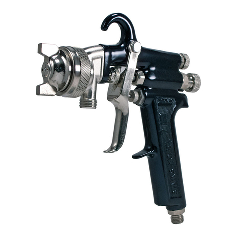
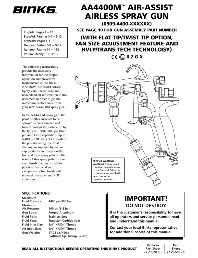
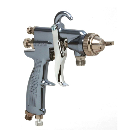
Binks AA4400M User manual

EN
77-2922-R10.1 (2/2016) 1 / 13
SERVICE MANUAL
SPECIFICATIONS:
Maximum Fluid Pressure: 303 bar [4,400 psi]
Maximum Air Pressure: 6.8 bar [100 psi]
Gun Body: Forged Aluminum
Fluid Path: Stainless Steel
Fluid Seat: Tungsten Carbide Seat
Fluid Inlet Size: 1/4" NPS(m) Thread
Air Inlet Size: 1/4" BSP/NPS(m) Thread
Gun Weight: 490 g [17.28 oz.]
(without Tip, Aircap, Guard)
AA4400M™AIR-ASSIST
AIRLESS SPRAY GUN
The following instructions provide the necessary
information for the proper operation and preventive
maintenance of the Binks AA4400M Air-Assist Airless
Spray Gun. Please read and understand all information
in this document in order to get the maximum
performance from your new AA4400M spray gun.
In the AA4400M spray gun, the paint or other material
to be sprayed is pre-atomized and forced through the
carbide tip by the typical 110-262 bar [1,600-3,800 psi]
fluid pressure (with capabilities up to 303 bar [4,400
psi]). As a result of the pre-atomizing, the final shaping
air supplied by the air cap produces an exceptionally
fine and even spray pattern. The result of this spray
pattern is an even finish that lends itself to products
that need an exceptionally fine finish with reduced
overspray and VOC emissions.
FLAT TIP REVERSIBLE TWIST TIP

EN
77-2922-R10.1 (2/2016)2 / 13
EC Declaration of Conformity
We: Finishing Brands UK, declare that the above product conforms with the Provisions of:
Machinery Directive 2006/42/EC
ATEX Directive 94/9/EC
by complying with the following statutory documents and harmonised standards:
BS EN 1953:2013 Atomising and spraying equipment for coating materials – Safety requirements
EN ISO 12100-1:2010 Safety of Machinery – Basic concepts, general principles for design – Basic terminology, methodology
EN ISO 12100-2:2010 Safety of Machinery – Basic concepts, general principles for design – Technical principles
EN 14462:2015 Surface treatment equipment – Noise test code for surface treatment equipment including its ancillary handling equipment –
Accuracy grades 2 and 3
EN ISO 11201:2010 Acoustics – Noise by machinery and equipment – Determination of emission sound pressure levels at a work station and at
other specified positions in an essentially free field over a reflecting plane with negligible environmental corrections
EN ISO 20643:2008 Mechanical vibration – Hand held and hand guided machinery – Principles for evaluation of vibration emission
EN ISO 28662-1 Hand-held portable power tools – Measurement of vibrations at the handle
EN 12096:1997 Mechanical vibration – Declaration and verification of vibration emission values
EN1127-1:2011 Explosive atmospheres – Explosion prevention – Basic concepts
EN 13463-1:2009 Non electrical equipment for use in potentially explosive atmospheres – Basic methods and requirements
Chuck McCulloch
December 31, 2015
The Spray Gun models listed in the following declaration of conformity may be used in some potentially explosive atmospheres ONLY when the
special conditions for safe installation and operation have been followed as expressed in this user manual (Part Sheet). These models are
approved to ATEX regulations 94/9/EC, protection level: II 2 G X: Suitable for use in Zones 1 and 2.
!
WARNING
The spray gun must be earthed to dissipate any electrostatic charges which may be created by fluid or air flows.
This can be achieved through the spray gun mounting, or conductive air/fluid hoses. Electrical bond from the spray
gun to earth should be checked and a resistance of less than 10
6
Ohms is required.
This Product is designed for use with: Solvent and water based materials
Suitable for use in hazardous area: Zone 1 & 2
Protection Level: II 2 G X
Vibration Level: N/A
Sound Pressure Level: Available on request
Sound Power Level: Available on request
Manufacturer: Carlisle Fluid Technologies
320 Philips Ave.
Toledo, OH 43612

EN
77-2922-R10.1 (2/2016) 3 / 13
WARNING
!
In this part sheet, the words WARNING, CAUTION and NOTE are used to emphasize important safety information as follows:
!
CAUTION
Hazards or unsafe practices which could
result in minor personal injury, product or
property damage.
!
WARNING
Hazards or unsafe practices which could
result in severe personal injury, death or
substantial property damage.
NOTE
Important installation, operation or
maintenance information.
READ THE FOLLOWING WARNINGS BEFORE USING THIS EQUIPMENT.
IT IS THE RESPONSIBILITY OF THE EMPLOYER TO PROVIDE THIS INFORMATION TO THE OPERATOR OF THE EQUIPMENT.
FOR FURTHER SAFETY INFORMATION REGARDING BINKS AND DEVILBISS EQUIPMENT, SEE THE GENERAL EQUIPMENT SAFETY BOOKLET (77-5300).
READ THE MANUAL
Before operating finishing equipment, read and understand all
safety, operation and maintenance information provided in the
operation manual.
TOXIC FLUID & FUMES
Hazardous fluid or toxic fumes can cause serious injury or death if
splashed in the eyes or on the skin, inhaled, injected or swallowed.
LEARN and KNOW the specific hazards or the fluids you are using.
MEDICAL ALERT
Any injury caused by high pressure liquid can be serious. If you are
injured or even suspect an injury:
a) Go to an emergency room immediately.
b) Tell the doctor you suspect an injection injury.
c) Show the doctor this medical information or the medical alert card provided
with your airless spray equipment.
d) Tell the doctor what kind of fluid you were spraying or dispensing.
e) Refer to the Material Safety Data Sheet for specific information.
WEAR SAFETY GLASSES
Failure to wear safety glasses with side shields could result in serious
eye injury or blindness.
OPERATOR TRAINING
All personnel must be trained before operating finishing equipment.
DE-ENERGIZE, DEPRESSURIZE, DISCONNECT AND LOCK
OUT ALL POWER SOURCES DURING MAINTENANCE
Failure to De-energize, disconnect and lock out all power supplies
before performing equipment maintenance could cause serious
injury or death.
HIGH PRESSURE CONSIDERATION
High pressure can cause serious injury. Relieve all pressure before
servicing. Spray from the spray gun, hose leaks, or ruptured
components can inject fluid into your body and cause extremely
serious injury.
PRESSURE RELIEF PROCEDURE
Always follow the pressure relief procedure in the equipment
instruction manual.
GET IMMEDIATE MEDICAL ATTENTION
To prevent contact with the fluid, please note the following:
a) Never point the gun/valve at anyone or any part of the body.
b) Never put hand or fingers over the spray tip.
c) Never attempt to stop or deflect fluid leaks with your hand, body, glove or
rag.
d) Always have the tip guard on the spray gun before spraying.
e) Always ensure that the gun trigger safety operates before spraying.
f) Always lock the gun trigger safety when you stop spraying.
EQUIPMENT MISUSE HAZARD
Equipment misuse can cause the equipment to rupture, malfunction,
or start unexpectedly and result in serious injury.
PROJECTILE HAZARD
You may be injured by venting liquids or gases that are released
under pressure, or flying debris.
PINCH POINT HAZARD
Moving parts can crush and cut. Pinch points are basically any areas
where there are moving parts.
NOISE HAZARD
You may be injured by loud noise. Hearing protection may be
required when using this equipment.
WEAR RESPIRATOR
Toxic fumes can cause serious injury or death if inhaled. Wear a
respirator as recommended by the fluid and solvent manufacturer’s
Material Safety Data Sheet.
KEEP EQUIPMENT GUARDS IN PLACE
Do not operate the equipment if the safety devices have been
removed.
INSPECT THE EQUIPMENT DAILY
Inspect the equipment for worn or broken parts on a daily basis. Do
not operate the equipment if you are uncertain about its condition.
NEVER MODIFY THE EQUIPMENT
Do not modify the equipment unless the manufacturer provides
written approval.
KNOW WHERE AND HOW TO SHUT OFF THE EQUIPMENT IN
CASE OF AN EMERGENCY
STATIC CHARGE
Fluid may develop a static charge that must be dissipated through
proper grounding of the equipment, objects to be sprayed and all
other electrically conductive objects in the dispensing area. Improper
grounding or sparks can cause a hazardous condition and result in
fire, explosion or electric shock and other serious injury.
PROP 65 WARNING
WARNING: This product contains chemicals known to the
State of California to cause cancer and birth defects or other
reproductive harm.

EN
77-2922-R10.1 (2/2016)4 / 13
1. Connect your high-pressure fluid hose to the gun fluid
inlet and tighten securely.
2. Connect your air hose to the gun air connection and
tighten securely.
3. Slowly increase air to the pump to obtain a fluid pressure
at the gun’s lower end of the pressure range. A typical
starting fluid pressure is 17 bar [250 psi]. Actual starting
pressure points may be higher or lower than 17 bar [250
psi] and depend on the setup including the type of pump
used, the type of material sprayed, and the spray gun
itself.
4. Using the control knob on the air regulator, set the air
pressure at zero.
5. To test the spraying pattern, spray a piece of wood or
cardboard with a fast pass about one foot away from the
surface. The results of the test will allow you to
determine the uniformity of the particle size and
spraying pattern.
6. If the spraying pattern develops tails or is not uniform,
gradually increase the air pressure as necessary to
develop a uniform spraying pattern. 1 bar [14 psi] is the
maximum inlet air pressure for HVLP (1 bar [15 psi]
max. for HVLP twist tip cap), or use 1.4-2.8 bar [20-40
psi] inlet air pressure for LVMP. The HVLP flat tip and
twist tip air caps consume 230 L/m [8.3 SCFM] air at
their respective maximum inlet air pressures. The
LVMP flat tip and twist tip air caps consume
368 L/m
[13 SCFM]
at 2.1 bar [30 psi] inlet air pressure. The air
is used to assist the atomization of the coating.
7. If the quality of spray is acceptable, begin spraying. If
the spraying rate is too slow to keep up with the
production line speed, or if the quantity of material
sprayed is inadequate for acceptable coverage, gradually
increase the fluid pressure in 3.4 bar [50 psi] increments
using the fluid regulator control knob. However, note
that as the fluid pressure increases, more air is needed to
eliminate the tails.
Consistency in spraying can be increased across spray gun
operators and similar spraying jobs by developing pressure
standardization charts. Repeat step 6 until the required
material coverage and spraying speed are achieved. If the
maximum fluid pressure is reached before the required
material coverage and spraying speed are achieved, you may
need to switch to a larger fluid tip.
TYPICAL HOOK-UP
Fan pattern adjustment: turn knob counterclockwise to
decrease pattern; clockwise to increase pattern (Fig. 2).
SPRAY GUN SET-UP
Figure 2
Fan
Adjustment
Control Knob
When using the
twist tip air cap, the
primary purpose of
the fan pattern
adjustment knob is
to eliminate tails in
the spray pattern.
FLUID TIP SELECTION
Factors to consider in selecting a fluid tip for an air-assist
airless spray gun include (1) the size of the parts being
sprayed; (2) the production line speed; (3) the material
flow rate and film thickness; (4) the viscosity of the
material applied; (5) the type of material applied; and (6)
the quality of atomization of the coating required.
The selection of a fluid tip necessary to perform a
specific spraying job is best determined through a
combination of experimentation and expert advice from
your material and equipment suppliers.
FLUID HOSES
Air-assist airless spray guns operate at fluid pressures
higher than operating pressures of air spray guns. As a
result, when operating an air-assist airless spray gun, it is
critical to select the appropriate fluid hose that is rated for
the pressure range at which the airless gun is operated.
NOTE
For HVLP spray, fan adjustment feature requires 1 bar [14
psi] max. of air inlet pressure (1 bar [15 psi] max. for HVLP
twist tip.) For LVMP spray, fan adjustment requires
approximately 1.4-2.8 bar [20-40 psi] of air inlet pressure.
Higher fluid pressure requires higher air inlet pressures to
accommodate pattern adjustment.
NOTE
Before proceeding, make sure trigger lock is engaged.
NOTE
Do not hang gun by trigger. This will cause needle damage
or malfunction.
Pump
Regulator
Regulator
Air
Air
Air
Fluid
Fluid Filter
Oil and Water
Extractor
Figure 1
Air
In
Gun

EN
77-2922-R10.1 (2/2016) 5 / 13
TROUBLESHOOTING DEFECTIVE SPRAY PATTERNS
The following procedure summarizes the steps that an
operator must immediately take when the first signs of a
defective spray pattern emerge.
1. Check the external portion of the fluid tip for material
buildup. If buildup has occurred, secure the gun
trigger safety switch and clean the gun fluid tip with a
non-metal soft brush.
2. If the spray pattern exhibits signs of tails at the top or
bottom ends of the pattern, increase the air pressure
gradually until the tails disappear.
3. If increasing air pressure does not dissipate the tails,
the fluid tip may be worn and may need to be
replaced. Another sign of the need to replace a worn
tip is a gradual decline in spraying pattern width.
4. If cleaning or replacing the fluid tip does not dissipate
the tails; the spraying defect is most likely due to the
material temperature and/or viscosity.
5. If pattern pulsation or blinking occurs, check the
pressure regulators, all downstream regulators, and the
pump. These may require further adjustment or even
repairs.
Figure 3
Correct
Pattern
Tails
GENERAL TROUBLESHOOTING
IMPORTANT REGULATORY NOTE
The AA4400M Air-Assist H.V.L.P. hand spray gun combines the proven efficiency of the Binks compliant spray guns with
air-assist atomization to yield a reliable, carefully engineered compliant spray gun. With 25' of 5/16" I.D. air hose and
regulator set at only 1.4 bar [20 psi] the compliant air cap registers 0.7 bar [10 psi] of atomization air to shape and soften the
spray pattern. The AA4400M air-assist H.V.L.P. gun operates at high transfer efficiencies and fully complies with all
government regulations for H.V.L.P. spray guns.
Max. Fluid Input: 303 bar [4400 psi]
Max. static air pressure at regulator with 25' of hose to inlet: 1.4 bar [20 psi]
Max. Dynamic Gun Inlet Air Pressure: 1 bar [14 psi]
Gun Body: Forged Aluminum Alloy
Fluid Path: Stainless Steel and Tungsten Carbide / PEEK
PROBLEM CAUSE ACTION
Fluid leaking from
through the seal
Worn seal or needle shaft.
Loose needle seal.
Replace needle assembly (18).
Tighten packing nut gently until leak stops.
Fluid leaking from the
front of the gun
Needle ball worn or damaged.
Worn seat assembly.
Replace needle assembly (18).
Replace fluid seat (3/3A).
Fluid in air passages Spray tip seal leaking.
Leaking around fluid seat.
Tighten air cap/nozzle guard assembly (7)
Replace carbide tip assembly (5/5A).
Tighten or replace fluid seat (3/3A).
Slow fluid shut off Fluid buildup on needle assembly. Clean or replace needle assembly (18).
No fluid output when
triggered
Tip orifice plugged.
Needle is damaged or broken.
Fluid filter or fluid hose plugged.
For flat tip: Turn off fluid supply. Relieve pressure into a closed earth-
grounded container. Engage trigger safety. Remove air cap/nozzle
guard assembly (6) and the carbide tip (5). Clean or replace carbide
tip assembly (5).
For twist tip: Rotate twist tip (5A) in aircap (6A) and spray into a
closed-grounded container to try clear tip of any debris. If that fails
to unplug the tip then remove, clean and replace twist tip.
Turn off fluid supply. Relieve pressure into a closed-grounded
container. Remove trigger (10). Replace needle assembly (18)
Turn off fluid supply. Relieve pressure into a closed-grounded
container. Turn off air supply to pump and relieve fluid pressure with
bypass valve. Engage trigger safety. Very slowly loosen the hose
connection at the gun to relieve any pressure in hose. Remove hose
and clear obstruction. NOTE: When replacing filter, use two
wrenches—one to hold tube (11) in place and prevent twisting, and
the other to remove nut (14). Only tighten nut (14) from 12-15 N-m
[9 -11 ft.-lbs.]
(Refer to page 12 when referencing part numbers in brackets.)
CAUTION
Always engage trigger lock and relieve fluid pressure before
servicing gun.
!

EN
77-2922-R10.1 (2/2016)6 / 13
PROBLEM CAUSE ACTION
Fluttering Spray Pattern Insufficient fluid supply. Adjust fluid regulator or fill fluid supply
tanks.
Air in paint supply line. Check and tighten pump siphon hose
connections, bleed air from paint line.
Attempting to “feather” (Partially Cannot feather with an AA4400M gun.
trigger gun).
Striping Spray – Fingers Carbide tip partially plugged. Clean or replace carbide tip assembly.
Irregular Pattern Fluid builds up on carbide tip, or tip Clean carbide tip.
partially plugged.
On defective side of pattern, air horn Clean air horn holes with solvent and
holes are plugged. a soft brush.
Pattern pushed to one side, same On defective side of pattern, air horn Clean air horn holes with solvent and
side of air cap gets dirty holes are plugged. a soft brush or toothpick.
SPRAY PATTERN TROUBLESHOOTING
AIR-ASSIST AIRLESS SPRAY GUN MAINTENANCE AND CLEANING
Maintenance of air-assist airless spray guns includes (1)
fluid tip wear and replacement; (2) lubrication; and (3)
cleaning of the gun.
FLUID TIP
Operating an air-assist airless spray gun with a worn fluid
tip will result in increased usage of spraying material and
therefore, HAP emissions. For example, an increase in
the diameter of a tip from 0.38-0.53 mm [0.015-0.021"]
due to wear can result in up to a 100 percent increase in
material consumption and cost. To prevent waste in
spraying material and non-value-adding costs, a
maintenance schedule that includes fluid tip inspection
and replacement must be established.
LUBRICATION
Proper lubrication is essential for optimum spray gun
performance. Lubrication allows the equipment to operate
easily and correctly. The spray gun should be lubricated
after each cleaning. The points that need lubrication
during the maintenance of air-assist airless spray guns
include the fluid needle packing and trigger pivot point.
Gun lube is used to lubricate the fluid needle packing and
trigger pivot point.
CLEANING
The following steps summarize the procedure for
cleaning air-assist airless spray guns:
1. Turn off the atomizing air supply to the gun.
2. Turn off air supply to the pump and relieve fluid
pressure. This may be accomplished by opening the
bypass/priming valve, if so equipped.
3. Place the siphon (suction) tube into a solvent container.
If pump is directly immersed in material, remove the
pump and immerse it in a solvent container.
4. Place the gun trigger safety switch in the locked
position.
5. Remove the fluid tip and place it in a closed solvent
container.
6. Adjust the pump air supply regulator to its lowest
level (counter-clockwise).
7. Place the gun trigger safety switch in the unlocked
position.
8. Turn on the air supply to the pump and close the
bypass/priming valve, if so equipped.
9. Slowly adjust the pump air supply regulator until the
pump begins to cycle.
10. Trigger the gun into a closed container until the fluid
runs clear.
CAUTION
Never immerse the entire gun in solvent or thinners. Some gun
parts will lose their lubricative film and wear more quickly.
Additionally, solvents may carry impurities throughout the gun
body and allow them to clog small air and fluid passages.
!
NOTE
Use only compatible solvents that are identified as approved
for cleaning and wash-off use.
WARNING
Failure to reduce pump air supply pressure or to use a
closed container can result in material “bounce-back”.
Material “bounce back” can cause injury and damage.
!
NOTE
During cleaning, the gun may only be sprayed into a closed
container, never flush the gun into the air or spray booth.

EN
77-2922-R10.1 (2/2016) 7 / 13
CLEANING (Continued)
11. Using a rag dampened with solvent, wipe the exterior
surface of the gun. Additionally, some solvents are
prohibited from being used for cleaning. The operator
must take care to use only approved cleaning solvents
for equipment cleaning. These materials are clearly
labeled as approved for cleaning and wash off
operations. If the operator has any question on
selecting appropriate cleaning solvents, the operator
should consult a supervisor or plant environmental
staff.
REPLACING FLUID NOZZLE AND/OR FLUID NEEDLE ASSEMBLY
Fig. 11Fig. 10
Fig. 12
REASONS TO REPLACE NOZZLE AND/OR NEEDLE ASSEMBLY:
A) Fluid leak through fluid nozzle.
B) Slow shut off of fluid.
C) No fluid when gun triggered.
REPLACING THE FLUID NOZZLE
1. Remove air cap along with spray tip. (See fig 4)
2. While fully depressing the trigger remove the fluid nozzle and
gasket. (See fig 5)
3. Check baffle plate for wear. If worn replace with new part.
(See fig 6)
4. While fully depressing the trigger install the new fluid nozzle
and gasket. Torque fluid nozzle from 12-15 N-m [9-11 ft-lbs].
(See fig 5) .
5. Replace the air cap along with spray tip (See fig 4)
REPLACING THE FLUID NEEDLE ASSEMBLY
1. Remove the trigger by removing the trigger screw and trigger
nut. (See fig 7)
2. Completely unscrew needle packing nut. (See fig 8)
3. Unscrew blanking cap and remove the needle spring and pad.
(See figs 9 & 10)
4. Ensure the spring pad has not been worn down and clean the
spring of any debris. (See fig 11)
5. Remove the needle assembly. (See fig 12)
6. Insert new needle assembly and new spring if necessary. (See
figs 12 & 10) Ensure the spring pad is attached to the spring.
7. Screw on blanking cap. (See fig 9)
8. Gently tighten needle packing nut. DO NOT OVER TIGHTEN.
(See fig 8)
9. Replace trigger, trigger screw and trigger nut. (See fig 7)
10. Operate gun with fluid and adjust tightness of packing nut as
necessary to prevent fluid leak. (See fig 8)
CAUTION
Always ensure that all fluid and air pressure to the gun has been dis-
charged before proceeding with any repairs.
!
CAUTION
Do not remove fluid tube when replacing the fluid nozzle.
!
Fig. 4
Fig. 7
Fig. 9
Fig. 6
Fig. 8
Fig. 5
Nozzle with
gasket

EN
77-2922-R10.1 (2/2016)8 / 13
Fig. 17
Fig. 19
Fig. 21
Fig. 20
Fig. 22
REASONS TO SERVICE AIR VALVE:
A) Air valve not functioning correctly (may need cleaning).
B) Routine maintenance.
C) Air leaks (advise replacement, see p8)
1. Remove trigger and fluid tube assembly. (See fig 13 & 14)
2. Unscrew air valve using 14 mm wrench. (See fig 15)
3. Remove air valve by gripping stem. (See fig 16)
4. Remove spring with spring pad. (See fig 17)
5. DO NOT REMOVE REAR SEAL FROM GUN BODY.
(See fig 18)
6. DO NOT REMOVE PLASTIC CAGE FROM AIR VALVE
BODY AS THIS MAY DAMAGE THE CAGE. (See fig 19)
7. CLEAN
a. Remove all paint build up. (See fig 20)
b. The 4 poppet holes must be clear. (See fig 21)
c. Stem must be free to float in poppet. (See fig 22)
d. Stem must slide through cage bore with slight resistance
(due to seal).
e. Rear seal must look clean and in position in the bore.
(See fig 18)
f. If any of the above cannot be rectified, replace the air valve.
(See Replacing Air Valve p8)
8. Replace spring ensuring the end with the plastic bearing pad
goes in first. (See fig 17)
9. Insert air valve assembly into gun and carefully feed over the
spring and through the rear seal. (See fig 23)
10. Tighten air valve assembly using fingers first, and then tighten
with 14mm wrench. Torque from 24-30 N-m [18-22 ft-lbs].
(See fig 24)
11. Replace the fluid tube and trigger. (See figs 14 & 13)
12. If there is an air leak through the gun, the air valve may need
replacing. (See Replacing Air Valve p8)
SERVICING AIR VALVE
CAUTION
Always ensure that all fluid and air pressure to the gun has been dis-
charged before proceeding with any repairs.
!
Fig. 18
Fig. 16
Fig. 23
Fig. 15
Fig. 24
Fig. 13 Fig. 14

EN
77-2922-R10.1 (2/2016) 9 / 13
Fig. 29
Fig. 31
Fig. 33
Fig. 30
Fig. 32
REPLACING AIR VALVE
REASONS TO REPLACE AIR VALVE:
A) Air leak through the gun.
B) Air valve not operating correctly.
1. Remove trigger and fluid tube assembly. (See figs 25 & 26)
2. Unscrew air valve using 14 mm wrench. (See fig 27)
3. Remove air valve by gripping the stem. (See fig 28)
4. Remove spring with spring pad. (See fig 29)
5. Hook out rear seal using Service Tool. (See figs 30 & 31)
6. Clean air valve bores in gun body with the brush supplied in
the kit.
7. Place new rear seal onto Service tool; grooves must fit in
service tool form. (See fig 32)
8. Push rear seal firmly into hole up to shoulder, using Service
tool. (See figs 33 & 34)
9. Insert new spring, ensuring the end with the plastic bearing pad
goes in first. (See fig 29)
10. Insert air valve assembly into gun and carefully feed over the
spring and through the rear seal. (See fig 35)
11. Tighten air valve assembly using fingers first, then tighten with
14 mm wrench. Torque from 24-30 N-m [18 to 22 ft-lbs]. (See
fig 36)
12. Replace fluid tube and trigger. (See figs 26 & 25)
CAUTION
Always ensure that all fluid and air pressure to the gun has been dis-
charged before proceeding with any repairs.
!
Fig. 36
Fig. 34
Fig. 27 Fig. 28
Fig. 35
Fig. 25 Fig. 26

EN
77-2922-R10.1 (2/2016)10 / 13
TIP GUARD INSTALLATION
REASON TO INSTALL TIP GUARD:
To replace broken tip guard.
INSTRUCTIONS ARE VALID FOR BOTH FLAT TIP GUARD
AND TWIST TIP GUARD:
1. Disconnect all fluid and air hoses from the gun.
2. Insert the gun into a clamping vise with fluid nozzle facing
directly upwards. (See fig 37) Gun should be securely clamped
at the upper portion of the gun handle.
3. Assemble air cap and air cap ring together – less spray tip and
plastic tip guard. (See fig 38)
4. Install the air cap and air cap ring assembly onto the gun until it
is fully hand tightened. (See fig 39)
5. Slip on the plastic tip guard onto the air cap in proper
orientation. (See fig 40)
6. Place round bar screwdriver between open sections of the
plastic guard and push down with even pressure on both sides
of the plastic guard. (See fig 41)
7. The guard should snap into air cap groove securely. (See fig 42)
8. The aircap can now be removed to install the appropriate tip
for use.
CAUTION
Always ensure that all fluid and air pressure to the gun has been dis-
charged before proceeding with any repairs.
!
WARNING
For pressures over 69 bar [1000 psi] the tip guard must be in place for
added protection against skin injection.
!
Fig. 37
Fig. 41
Fig. 38
Fig. 42
Fig. 39 Fig. 40

EN
77-2922-R10.1 (2/2016) 11 / 13
AA4400M AIR-ASSIST AIRLESS SPRAY GUN
19
18
22
23 24
25 26
5A
3A
5B
6A
7A 8A
8B
8
7
6
2
3
4
5
1
15 16
17
10
9
11
29
30
31
TWIST TIP PARTS
FLAT TIP PARTS
12-15 N-m
[9-11 FT-LBS]
12-15 N-m
[9-11 FT-LBS]
24-30 N-m
[18-22 FT-LBS]
12-15 N-m
[9-11 FT-LBS]
24-30 N-m
[18-22 FT-LBS]
24-30 N-m
[18-22 FT-LBS]
19-22 N-m
[14-16 FT-LBS]
= TORQUE VALUE
Nm [in-lb or ft-lb]
= ITEM NUMBER
MAINTENANCE SYMBOLS:
#
#

EN
77-2922-R10.1 (2/2016)12 / 13
1 — GUN BODY .................................................... 1
2 SPA-71-K5 BAFFLE PLATE (KIT OF 5) ................................ 1
FLAT TIP COMPONENTS
3 54-5799-K
✙
FLUID SEAT (4400PSI) ...................................... 1
(TUNGSTEN CARBIDE) ..................................
4 SPA-98-K5 GASKET (KIT OF 5) .......................................... 1
5 114-XXXXX
■
FLAT TIP (FINE FINISH TIPS 9-XXXX-F)............ 1
6 54-5878-K
▼
FLAT TIP HVLP AIRCAP.................................... 1
(FLAT TIP LVMP AIRCAP 54-5797-K)
(AA-10 FLAT TIP HVLP AIRCAP 54-5890-K)
(FLAT TIP AIRCAP HVLP 54-5795)
7 54-5852 RETAINING RING.............................................. 1
8 54-5794
m
FLAT TIP GUARD.............................................. 1
TWIST TIP COMPONENTS
3A 54-5832-K
✙
TWIST TIP FLUID SEAT (4400PSI)..................... 1
(TUNGSTEN CARBIDE)
5A 9-XXX-75
■
TWIST TIP ......................................................... 1
5B 54-7539-K2 TWIST TIP BRACE (KIT OF 2) ........................... 1
6A 54-5924-K
▼
TWIST TIP HVLP AIRCAP ................................. 1
(TWIST TIP LVMP AIRCAP 54-5925-K)
7 54-5928 RETAINING RING.............................................. 1
8A 54-5921
m
TWIST TIP GUARD ........................................... 1
8B 54-5930
m
TWIST TIP GUARD SCREW............................... 1
ITEM PART
NO. NO. DESCRIPTION QTY.
9 SN-402-K AIR VALVE ASSEMBLY ..................................... 1
10 —
▲
TRIGGER........................................................... 1
11 54-5780 FLUID TUBE ASSEMBLY .................................. 1
15 SN-9-K3 AIR INLET FITTING 1/4” NPS (KIT OF 3).......... 1
16 —
●
FILTER BRACKET SCREW ................................. 1
17 —
●
FILTER BRACKET .............................................. 1
18 54-5826 FLUID NEEDLE ASSEMBLY KIT (4400PSI) ........ 1
19 54-5850 BLANKING NEEDLE NUT ................................. 1
22 54-5815 SPREADER VALVE ASSEMBLY.......................... 1
23 — # BODY BUSHING............................................... 1
24 — # BODY BUSHING GASKET................................. 1
25 —
▲
TRIGGER NUT................................................... 1
26 —
▲
TRIGGER SCREW .............................................. 1
29 54-1835 100 MESH DISC FILTER (1 PIECE)..................... 1
(60 MESH FILTER (KIT OF 5) 54-1836-K5)
30 —
*
DISC FILTER HOUSING ..................................... 1
31 —
*
DISC FILTER RETAINING NUT........................... 1
ITEM PART
NO. NO. DESCRIPTION QTY.
PARTS LIST
When ordering, please specify Part No. (Not all Part Nos. are available for purchasing.)
Refer to page 10 when referencing Item Nos.
▼All aircap kits are pre-assembled with Retaining ring and
appropriate tip guard. When switching from flat tip to
twist tip, or vice versa, be sure to order correct fluid seat
(3/3A). For twist tip, item 5B will also be needed.
■Refer to page 12 for available tip sizes. When purchasing
twist tip, discard packaged brace/seal and use Item 5B only.
✙Pre-assembled with gasket SPA-98.
▲Available as part of kit 54-5835.
●Available as part of kit 54-5827.
# Available as part of kit 54-5829.
mMandatory for operating pressures above 69 bar [1000 psi].
* Available as part of kit 54-4726-K. Order filter (29)
separately.
AA4400M AIR-ASSIST AIRLESS SPRAY GUN
ACCESSORIES
FITTINGS
54-4976-K3 3-Pack 1/4" NPT(f) x 3/8" O.D. Push-In Tube Fitting
(optional)
72-2332 Fluid Inlet Swivel (1/4"m x 1/4"f)
FLUID FILTER
54-1835 100 Mesh (Disc) Filter
54-1836 60 Mesh (Disc) Filter
HVLP AIRCAP TEST KITS
54-5882-K Flat Tip HVLP Aircap Test Kit (Incl Gauge)
for 54-5878 air cap
54-5836-K Flat Tip HVLP Aircap Test Kit (Incl Gauge)
for 54-5795 air cap
54-5837-K Twist Tip HVLP Aircap Test Kit (Incl Gauge)
TEST GAUGES
54-5327 HVLP Test Gauge

EN
77-2922-R10.1 (2/2016) 13 / 13
STANDARD FLAT TIP SELECTION CHARTS
GPM
FAN CAPACITY @
WIDTH 34 BAR [500 PSI]
PART NUMBER DESCRIPTION ORIFICE (IN.) WATER
114-00704 TIP ASSEMBLY .007 4 .028
114-00706 TIP ASSEMBLY .007 6 .028
114-00708 TIP ASSEMBLY .007 8 .028
114-00902 TIP ASSEMBLY .009 2 .039
114-00906 TIP ASSEMBLY .009 6 .039
114-00908 TIP ASSEMBLY .009 8 .039
114-00910 TIP ASSEMBLY .009 10 .039
114-00912 TIP ASSEMBLY .009 12 .039
114-01104 TIP ASSEMBLY .011 4 .060
114-01106 TIP ASSEMBLY .011 6 .060
114-01108 TIP ASSEMBLY .011 8 .060
114-01110 TIP ASSEMBLY .011 10 .060
114-01112 TIP ASSEMBLY .011 12 .060
114-01114 TIP ASSEMBLY .011 14 .060
114-01304 TIP ASSEMBLY .013 4 .090
114-01306 TIP ASSEMBLY .013 6 .090
114-01308 TIP ASSEMBLY .013 8 .090
114-01310 TIP ASSEMBLY .013 10 .090
114-01312 TIP ASSEMBLY .013 12 .090
114-01314 TIP ASSEMBLY .013 14 .090
114-01316 TIP ASSEMBLY .013 16 .090
114-01506 TIP ASSEMBLY .015 6 .120
114-01508 TIP ASSEMBLY .015 8 .120
114-01510 TIP ASSEMBLY .015 10 .120
114-01512 TIP ASSEMBLY .015 12 .120
114-01514 TIP ASSEMBLY .015 14 .120
114-01516 TIP ASSEMBLY .015 16 .120
114-01518 TIP ASSEMBLY .015 18 .120
114-01706 TIP ASSEMBLY .017 6 .160
114-01708 TIP ASSEMBLY .017 8 .160
114-01710 TIP ASSEMBLY .017 10 .160
114-01712 TIP ASSEMBLY .017 12 .160
114-01714 TIP ASSEMBLY .017 14 .160
114-01716 TIP ASSEMBLY .017 16 .160
114-01718 TIP ASSEMBLY .017 18 .160
114-01906 TIP ASSEMBLY .019 6 .190
114-01908 TIP ASSEMBLY .019 8 .190
114-01910 TIP ASSEMBLY .019 10 .190
114-01912 TIP ASSEMBLY .019 12 .190
114-01914 TIP ASSEMBLY .019 14 .190
114-01916 TIP ASSEMBLY .019 16 .190
114-01918 TIP ASSEMBLY .019 18 .190
114-02110 TIP ASSEMBLY .021 10 .240
114-02112 TIP ASSEMBLY .021 12 .240
114-02114 TIP ASSEMBLY .021 14 .240
114-02116 TIP ASSEMBLY .021 16 .240
114-02118 TIP ASSEMBLY .021 18 .240
114-02410 TIP ASSEMBLY .024 10 .310
114-02412 TIP ASSEMBLY .024 12 .310
114-02414 TIP ASSEMBLY .024 14 .310
114-02416 TIP ASSEMBLY .024 16 .310
114-02418 TIP ASSEMBLY .024 18 .310
114-02710 TIP ASSEMBLY .027 10 .385
114-02712 TIP ASSEMBLY .027 12 .385
114-02714 TIP ASSEMBLY .027 14 .385
114-02716 TIP ASSEMBLY .027 16 .385
114-02718 TIP ASSEMBLY .027 18 .385
TWIST TIP SELECTION CHARTS
FAN GPM
WIDTH CAPACITY @
PART NUMBER DESCRIPTION ORIFICE (IN.) 152 BAR [2200 PSI]
9-307-75 TWIST TIP .007 6 0.05
9-309-75 TWIST TIP .009 6 0.09
9-409-75 TWIST TIP .009 8 0.09
9-509-75 TWIST TIP .009 10 0.09
9-211-75 TWIST TIP .011 4 0.12
9-311-75 TWIST TIP .011 6 0.12
9-411-75 TWIST TIP .011 8 0.12
9-511-75 TWIST TIP .011 10 0.12
9-611-75 TWIST TIP .011 12 0.12
9-213-75 TWIST TIP .013 4 0.18
9-313-75 TWIST TIP .013 6 0.18
9-413-75 TWIST TIP .013 8 0.18
9-513-75 TWIST TIP .013 10 0.18
9-613-75 TWIST TIP .013 12 0.18
9-713-75 TWIST TIP .013 14 0.18
9-215-75 TWIST TIP .015 4 0.24
9-315-75 TWIST TIP .015 6 0.24
9-415-75 TWIST TIP .015 8 0.24
9-515-75 TWIST TIP .015 10 0.24
9-615-75 TWIST TIP .015 12 0.24
9-715-75 TWIST TIP .015 14 0.24
9-217-75 TWIST TIP .017 4 0.31
9-317-75 TWIST TIP .017 6 0.31
9-417-75 TWIST TIP .017 8 0.31
9-517-75 TWIST TIP .017 10 0.31
9-617-75 TWIST TIP .017 12 0.31
9-717-75 TWIST TIP .017 14 0.31
9-419-75 TWIST TIP .019 8 0.38
9-519-75 TWIST TIP .019 10 0.38
9-619-75 TWIST TIP .019 12 0.38
9-421-75 TWIST TIP .021 8 0.47
9-521-75 TWIST TIP .021 10 0.47
9-621-75 TWIST TIP .021 12 0.47
9-523-75 TWIST TIP .023 10 0.57
9-623-75 TWIST TIP .023 12 0.57
9-525-75 TWIST TIP .025 10 0.67
9-625-75 TWIST TIP .025 12 0.67
9-627-75 TWIST TIP .027 12 0.74
9-631-75 TWIST TIP .031 12 1.03
9-435-75 TWIST TIP .035 8 1.31
9-635-75 TWIST TIP .035 12 1.31
FINE FINISH FLAT TIP SELECTION CHARTS
GPM
FAN CAPACITY @
WIDTH 34 BAR [500 PSI]
PART NUMBER DESCRIPTION ORIFICE (IN.) WATER
9-0909-F FINE FINISH TIP 0.009 9 0.039
9-0911-F FINE FINISH TIP 0.009 11 0.039
9-1109-F FINE FINISH TIP 0.011 9 0.06
9-1111-F FINE FINISH TIP 0.011 11 0.06
9-1113-F FINE FINISH TIP 0.011 13 0.06
9-1115-F FINE FINISH TIP 0.011 15 0.06
9-1309-F FINE FINISH TIP 0.013 9 0.09
9-1311-F FINE FINISH TIP 0.013 11 0.09
9-1313-F FINE FINISH TIP 0.013 13 0.09
9-1315-F FINE FINISH TIP 0.013 15 0.09
9-1509-F FINE FINISH TIP 0.015 9 0.12
9-1511-F FINE FINISH TIP 0.015 11 0.12
9-1513-F FINE FINISH TIP 0.015 13 0.12
9-1515-F FINE FINISH TIP 0.015 15 0.12
9-1517-F FINE FINISH TIP 0.015 17 0.12
9-1709-F FINE FINISH TIP 0.017 9 0.16
9-1711-F FINE FINISH TIP 0.017 11 0.16
9-1713-F FINE FINISH TIP 0.017 13 0.16
9-1715-F FINE FINISH TIP 0.017 15 0.16
9-1717-F FINE FINISH TIP 0.017 17 0.16
Fan width based on 69 bar [1000 PSI] with water
305 mm [12"] from surface. Actual results may
vary, depending on material viscosity.
FULL GUN ASSEMBLIES
DESCRIPTION ASS'Y NUMBER
AA4400M HVLP FLAT TIP GUN ASSEMBLY (NO TIP INCL.) 0909-4400-HF0000
AA4400M HVLP FLAT TIP GUN WITH AA-10 AIRCAP (NO TIP INCL.)
0909-4400-10000
AA4400M LVMP FLAT TIP GUN ASSEMBLY (NO TIP INCL.)
0909-4400-LF000
DESCRIPTION ASS'Y NUMBER
AA4400M HVLP TWIST TIP GUN ASSEMBLY (NO TIP INCL.) 0909-4400-HT0000
AA4400M LVMP TWIST TIP GUN ASSEMBLY (NO TIP INCL.)
0909-4400-LT0000
TWIST TIP NOTE
When switching from flat tip to twist tip, increase pattern
size by 51 mm [2 inches] and use air adjustment to turn
down to desired size.
Fan width based on 152 bar [2200 psi] with latex paint
305 mm [12"] from surface. Actual results may vary,
depending on material viscosity.
Fan width based on 69 bar [1000 PSI] with water
305 mm [12"] from surface. Actual results may vary,
depending on material viscosity.

ES
77-2922-R10.1 (2/2016)ES-1 / 13
MANUAL DE SERVICIO
PISTOLA ROCIADORA AIRLESS
ASISTIDA POR AIRE AA4400M™
Las siguientes instrucciones proporcionan la información
necesaria para la debida operación y el mantenimiento
preventivo de la Pistola rociadora sin aire con asistencia
de aire AA4400M BINKS. Sírvase leer y comprender
toda la información contenida en este documento para
lograr el máximo nivel de desempeño de su nueva
Pistola rociadora AA4400M.
En la Pistola rociadora AA4400M, la pintura y otros
materiales que se van a rociar son pre-atomizados y
empujados a través de la boquilla de fluido por la
presión de fluido típica de 110-262 bar [1600-3800 psi]
(con capacidades hasta de 303 bar [4400 psi]). Como
resultado de la pre-atomización, el aire modelador final
suministrado por el casquillo de aire produce un patrón
de rociado excepcionalmente fino y uniforme. El
resultado de este patrón de rociado es un acabado
uniforme adecuado para productos que necesitan un
acabado excepcionalmente fino con menos exceso de
rociado y emisiones VOC.
ESPECIFICACIONES:
Presión máxima del fluido: 303 bar [4400 psi]
Presión máxima del aire: 6.8 bar [100 psi]
Cuerpo de la pistola: Aluminio forjado
Conducto del fluido: Acero inoxidable
Asiento del fluido: Asiento de carburo de tungsteno
Tamaño del orificio de entrada del fluido: Rosca de 1/4" NPS (m)
Tamaño del orificio de entrada del aire: Rosca de 1/4" BSP/NPS (m)
Peso de la pistola: 490 g [17.28 oz.]
(sin boquilla de fluido, boquilla de aire y guarda)
PUNTA PLANA PUNTA REVERSIBLE GIRATORIA

ES
77-2922-R10.1 (2/2016) ES-2 / 13
Declaración de conformidad de CE
Nosotros: Finishing Brands UK, declaramos que el producto anterior satisface los requisitos de la:
Directiva de Seguridad de Maquinarias 2006/42/EC
Directiva ATEX 94/9/EC
De conformidad con los siguientes documentos y normativa armonizada reglamentarios:
BS EN 1953:2013 Equipos de atomización y pulverización para materiales de recubrimiento – Requisitos de seguridad
EN ISO 12100-1:2010 Seguridad de las maquinarias – Conceptos básicos, principios generales de diseño – Terminología y metodología básicas
EN ISO 12100-2:2010 Seguridad de las maquinarias – Conceptos básicos, principios generales de diseño – Principios técnicos
EN 14462:2015 Equipos de tratamiento de superficies – Código de prueba de ruido para equipos de tratamiento de superficies incluyendo sus
equipos auxiliares de manipulación – Grados de precisión 2 and 3
EN ISO 11201:2010 Acústica – Ruido proveniente de máquinas y equipos – Determinación de los niveles de presión sonora de emisiones en
una estación de trabajo y en otras posiciones especificadas en un campo esencialmente libre sobre un plano reflector con correcciones
ambientales insignificantes
EN ISO 20643:2008 Vibración mecánica – Máquinas portátiles y guiadas a mano – Principios para evaluar la emisión de vibraciones
EN ISO 28662-1 Herramientas eléctricas/motorizadas manuales y portátiles – Medida de las vibraciones en el mango
EN 12096:1997 Vibración mecánica – Declaración y verificación de los valores de la emisión de vibraciones
EN1127-1:2011 Atmósferas explosivas – Prevención de explosiones – Conceptos básicos
EN 13463-1:2009 Equipos no eléctricos para uso en atmósferas potencialmente explosivas – Métodos básicos y requisitos
Chuck McCulloch
31 de diciembre de 2015
Los modelos de pistola pulverizadora listados en la siguiente declaración de conformidad se pueden utilizar en algunas atmósferas potencialmente
explosivas ÚNICAMENTE cuando las condiciones especiales para la instalación y la operación seguras se han seguido como se expresa en este
manual de usuarios (Hoja de piezas). Estos modelos están aprobados según regulaciones ATEX 94/9/EC, nivel de protección: II 2 G X: Aptos
para uso en las Zonas 1 y 2.
!
ADVERTENCIA
La pistola pulverizadora debe conectarse a tierra para disipar cualquier carga electrostática que pueda ser creada por
caudales de fluido o flujos de aire. Esto se puede lograr mediante la montura de la pistola pulverizadora o las
mangueras conductoras de aire/fluido. Se debe chequear la conexión eléctrica de la pistola pulverizadora a tierra y se
requiere de una resistencia de menos de 10
6
Ohm.
Este producto está diseñado para ser usado con: Materiales con base de solventes y de agua
Apto para uso en áreas peligrosas: Zona 1 y 2
Nivel de protección: II 2 G X
Nivel de vibración: N/A
Nivel de presión sonora: Disponible previa solicitud
Nivel de potencia acústica: Disponible previa solicitud
Fabricante: Carlisle Fluid Technologies
320 Philips Ave.
Toledo, OH 43612

ES
77-2922-R10.1 (2/2016)ES-3 / 13
ADVERTENCIA
En esta Hoja de piezas, las palabras ADVERTENCIA, PRECAUCIÓN y NOTA se emplean para enfatizar información de seguridad importante de la manera siguiente:
¡
PRECAUCIÓN
Prácticas peligrosas o inseguras que
pueden ocasionar lesiones personales
leves, daño al producto o a la propiedad
!
ADVERTENCIA
Prácticas peligrosas o inseguras que pueden
ocasionar lesiones personales graves, la
muerte o daño substancial a la propiedad.
NOTA
Información importante de instalación,
operación o mantenimiento.
LEA LAS SIGUIENTES ADVERTENCIAS ANTES DE USAR ESTE EQUIPO.
ES RESPONSABILIDAD DEL EMPLEADOR SUMINISTRAR ESTA INFORMACIÓN AL OPERADOR DEL EQUIPO.
PARA MÁS INFORMACIÓN DE SEGURIDAD ACERCA DE LOS EQUIPOS BINKS Y DEVILBISS, CONSULTE EL FOLLETO DE SEGURIDAD GENERAL DE LOS
EQUIPOS (77-5300).
LEA EL MANUAL
Antes de operar los equipos de acabado, lea y comprenda toda la
información de seguridad, operación y mantenimiento incluida en el
manual de operaciones.
FLUIDOS Y VAPORES TÓXICOS
Los fluidos peligrosos o los vapores tóxicos pueden ocasionar lesiones
graves o la muerte si se salpican a los ojos o la piel, se inhalan, se
inyectan o ingieren APRENDA y CONOZCA los peligros específicos de
los fluidos que está utilizando.
ALERTA MÉDICA
Cualquier lesión ocasionada por líquido de alta presión puede ser
grave. Si sufre una lesión o sospecha haber sufrido una:
a) Vaya a una sala de emergencia de inmediato.
b) Informe al médico que sospecha haber sufrido una lesión por inyección.
c) Muestre al médico esta información médica o la tarjeta de alerta médica
provista con su equipo atomizador sin aire.
d) Informe al médico acerca del tipo de fluido que estaba atomizando o aplicando.
e) Consulte la información específica en la Hoja de datos de seguridad.
USE GAFAS PROTECTORAS
No usar gafas protectoras con resguardos laterales puede ocasionar
lesiones graves en los ojos o ceguera.
CAPACITACIÓN DE LOS OPERADORES
Todos los miembros del personal deben ser capacitados antes de
operar los equipos de acabado.
DESACTIVE, DESPRESURICE, DESCONECTE Y BLOQUEE TODAS
LAS FUENTES DE ENERGÍA DURANTE EL MANTENIMIENTO
No desactivar, desconectar ni bloquear todas las fuentes de suministro
de energía antes de realizar operaciones de mantenimiento en los
equipos puede ocasionar lesiones graves o la muerte.
CONSIDERACIONES DE ALTA PRESIÓN
La alta presión puede ocasionar lesiones graves. Antes de reparar o
dar mantenimiento a los equipos, alivie toda la presión. El atomizado
de la pistola pulverizadora, las filtraciones de la manguera o
componentes averiados pueden inyectar fluido en su organismo y
ocasionar lesiones sumamente graves.
PROCEDIMIENTO DE LIBERACIÓN DE PRESIÓN
Siga siempre el procedimiento de liberación de presión que aparece
en el manual de instrucciones del equipo.
CONSIGA ATENCIÓN MÉDICA INMEDIATA
Para evitar el contacto con el fluido, tenga en cuenta lo siguiente:
a) Nunca apunte la pistola/válvula hacia ninguna persona ni hacia ninguna parte
del cuerpo.
b) Nunca ponga la mano ni los dedos sobre la punta atomizadora.
c) Nunca trate de detener ni desviar los escapes de fluido con la mano, el
cuerpo, guantes o trapos.
d) Antes de atomizar, tenga siempre el resguardo de la punta puesto en la
pistola pulverizadora.
e) Antes de atomizar, asegúrese siempre de que el seguro del disparador de la
pistola esté operativo.
f) Cuando deje de atomizar, póngale siempre el seguro al disparador de la pistola.
PELIGRO DE USO INDEBIDO DEL EQUIPO
El uso indebido del equipo puede ocasionar averías, mal
funcionamiento o activación imprevista lo que a su vez puede
producir lesiones graves.
PELIGRO DE PROYECTILES
Usted puede resultar lesionado por dar salida a líquidos o gases
liberados bajo presión o por restos que vuelan.
PELIGRO DE PUNTOS DE PRESIÓN
Las partes móviles pueden aplastar y ocasionar cortaduras. Los
puntos de presión son básicamente todas las áreas donde haya
partes móviles.
PELIGRO DE RUIDO
Usted puede resultar lesionado por el ruido muy fuerte. Podría
necesitar protección de los oídos al usar este equipo.
USE UN RESPIRADOR
La inhalación de vapores tóxicos puede ocasionar lesiones graves o la
muerte. Use un respirador como lo recomienda la Hoja de datos de
seguridad del fabricante del fluido y el solvente.
MANTENGA LAS DEFENSAS DEL EQUIPO EN SU LUGAR
No operar los equipos si los dispositivos de seguridad fueron retirados.
INSPECCIONE LOS EQUIPOS DIARIAMENTE
Inspeccione diariamente los equipos para verificar que no tengan
piezas gastadas o rotas. No opere los equipos si no está seguro de
su condición.
NUNCA MODIFIQUE LOS EQUIPOS
No modifique el equipo sin la autorización escrita del fabricante.
SEPA CÓMO Y DÓNDE DESACTIVAR LOS EQUIPOS EN CASO
DE EMERGENCIA.
CARGA ESTÁTICA
Los fluidos pueden generar una carga estática que debe ser disipada
mediante la debida conexión a tierra del equipo, los objetos que van
a ser atomizados y todos los demás objetos electroconductores en el
área de aplicación. La conexión a tierra indebida o las chispas
pueden ocasionar condiciones de peligro y producir incendios,
explosiones o descargas eléctricas y otras lesiones graves.
ADVERTENCIA PROP 65
ADVERTENCIA: Este producto contiene sustancias químicas que
según información en poder del estado de California producen cáncer,
defectos de nacimiento y otros daños al sistema reproductor.

ES
77-2922-R10.1 (2/2016) ES-4 / 13
1. Conecte su manguera de alta presión a la entrada de fluido de la
pistola y apriete bien.
2. Conecte su manguera de aire a la conexión de aire de la pistola y
apriete bien.
3. Aumente lentamente el aire hacia la bomba para obtener una
presión de fluido en el extremo más bajo del rango de la presión
de la pistola. Una presión de fluido inicial típica es 17 bar [250
psi]. Los puntos de presión inicial reales podrían ser superiores o
inferiores a 17 bar [250 psi] y dependen de la configuración,
incluyendo el tipo de bomba utilizada, el tipo del material rociado
y la pistola rociadora misma.
4. La perilla de control en el regulador del aire fija la presión del aire
en cero.
5. Para probar el patrón de rociado, rocíe un pedazo de madera o
cartón con una pasada rápida aproximadamente a un pie de
distancia de la superficie. Los resultados de la prueba le permitirán
determinar la uniformidad del tamaño de las partículas y el patrón
de rociado.
6. Si el patrón de rociado desarrolla colas o no es uniforme, aumente
gradualmente la presión del aire lo necesario para desarrollar un
patrón de rociado uniforme. 1 bar [14 psi] es la presión de aire de
entrada máxima para HVLP (alto volumen, baja presión) (1 bar
[15 psi] máx. para casquillo con punta giratoria HVLP) o utilice
una presión de aire de entrada de 1.4-2.8 bar [20-40 psi] para
LVMP (bajo volumen, presión media). Las boquillas de aire de
punta plana y punta giratoria HVLP consumen 230 L/m [8.3
SCFM] de aire a sus respectivas presiones de aire de entrada
máximas. Las boquillas de aire de punta plana y punta
giratoria LVMP consumen 368 L/m [13 SCFM] a una presión
de aire de entrada de 2.1 bar [30 psi]. El aire se utiliza para
ayudar con la atomización del recubrimiento.
7. Si la calidad del rociado es aceptable, comience a rociar. Si la
velocidad de rociado es muy lenta respecto de la velocidad de la
línea de producción o si la cantidad del material rociado es
inadecuada para una cobertura aceptable, aumente gradualmente la
presión del fluido en incrementos de 3.4 bar [50 psi] utilizando la
perilla de control del regulador de fluido. No obstante, tenga en
cuenta que a medida que aumenta la presión del fluido, se necesita
más aire para eliminar las colas.
La consistencia en el rociado se puede aumentar entre los operadores
de pistolas rociadoras y tareas de rociado similares mediante las
tablas de estandarización de presiones. Repita el paso 6 hasta que
lograr la cobertura del material y la velocidad de rociado requeridas.
Si la presión máxima del fluido se logra antes de lograr la cobertura
del material y la velocidad de rociado requeridas, usted tendría que
conseguir una punta de fluido más grande.
MONTAJE DE LA PISTOLA ROCIADORA
Bomba
Regulador
Regulador
Aire
Aire
Aire
Fluido
Filtro de fluido
Pistola
Extractor de
aceite y agua
Figura 1
Figura 2
Perilla de control
del ajuste del
abanico
Al usar el casquillo de
aire con punta
giratoria, el propósito
principal de la perilla
de ajuste del patrón
del ventilador es
eliminar las colas en
el patrón de rociado.
SELECCIÓN DE LA BOQUILLA DE FLUIDO
Los factores que se deben considerar al seleccionar una
boquillo de fluido para una pistola airless asistida por aire
incluyen (1) el tamaño de las partes que están siendo
rociadas; (2) la velocidad de la línea de producción; (3) el
caudal del material y el grosor de la película; (4) la
viscosidad del material aplicado; (5) el tipo de material
aplicado; y (6) la calidad de la atomización del
recubrimiento requerido.
La selección de una boquilla de fluido para realizar una tarea
específica de rociado se determina mejor mediante una
combinación de experimentación y el consejo profesional de
su proveedor de materiales y equipos.
MANGUERAS DE FLUIDO
Las pistolas rociadoras airless asistidas por aire funcionan con
presiones de fluido superiores a las presiones operativas de las
pistolas rociadoras con aire. Por consiguiente, al operar una
pistola airless asistida por aire, es esencial seleccionar la
manguera de fluido apropiada con clasificación para el rango
de presión con el que se opera la pistola sin aire.
Entrada
de aire
NOTA
Para rociado HVLP, la característica de ajuste del abanico requiere de una presión
de aire del orificio de entrada máxima de 1 bar [14 psi]. (1 bar [15 psi] máx. para
la boquilla giratoria HVLP). Para rociado LVMP, el ajuste del ventilador requiere de
una presión de aire del orificio de entrada de aproximadamente 1.4-2.8 bar [20-40
psi]. Una presión de fluido superior requiere de presiones superiores del orificio
de entrada del aire para dar cabida el ajuste del patrón.
NOTA
Antes de comenzar, asegúrese de que el seguro esté enganchado.
NOTA
No cuelgue la pistola por el gatillo. Esto dañaría la aguja o
causaría un mal funcionamiento de la pistola.
Ajuste del patrón del ventilador: gire la perilla en sentido
antihorario para disminuir el patrón; en sentido horario para
aumentar el patrón. (Fig. 2).
ENGANCHE TÍPICO:

ES
77-2922-R10.1 (2/2016)ES-5 / 13
LOCALIZACIÓN Y SOLUCIÓN DE PATRONES DE ROCIADO DEFECTUOSOS
El siguiente procedimiento resume los pasos que un operador
debe tomar inmediatamente al advertir los primeros signos de
un patrón de rociado defectuoso.
1. Verificar que no haya acumulación de material en la
porción externa de la punta de fluido. Si hubiese
acumulación, asegurar el interruptor de seguridad del
gatillo de la pistola y limpiar la boquilla de fluido de la
pistola con un cepillo suave no metálico.
2. Si advierte en el patrón de rociado signos de colas en el
extremo superior o en el inferior del patrón, aumentar la
presión del aire gradualmente hasta que desaparezcan
las colas.
3. Si al aumentar la presión de aire no disipa las colas, la
boquilla de fluido podría estar gastada lo que haría
necesario reemplazarla. Otro signo de la necesidad de
reemplazar una boquilla gastada es una disminución
gradual en el ancho del patrón de rociado.
4. Si al limpiar o reemplazar la boquilla de fluido no disipa
las colas; es muy probable que el defecto en el rociado se
deba a la temperatura y/o viscosidad del material.
5. Si hubiese pulsación o parpadeo en el patrón, revisar los
reguladores de presión, todos los reguladores corriente
abajo y la bomba. Estas piezas podrían necesitar ajuste o
incluso reparación.
Figura 3
Patrón
correcto
Colas
LOCALIZACIÓN Y SOLUCIÓN DE POSIBLES PROBLEMAS GENERALES
NOTA REGLAMENTARIA IMPORTANTE
La Pistola rociadora de mano H.V.L.P. asistida por aire AA4400M combina la eficacia probada de las pistolas rociadoras que cumplen
con las especificaciones de Binks con atomización con asistencia de aire para producir una pistola rociadora confiable, cuidadosamente
fabricada que cumple todos los requisitos reglamentarios. Con un juego de manguera de aire de 25 pies con diámetro interno de 5/16
de pulg. y regulador con sólo 1.4 bar [20 psi], el casquillo de aire que cumple con los requisitos reglamentarios, registra 0.7 bar[10 psi]
de aire de atomización para conformar y suavizar el patrón de rociado. La pistola H.V.L.P. con asistencia de aire AA1600M funciona con
altas eficiencias de transferencia y cumple plenamente con todos los reglamentos gubernamentales para pistolas rociadoras H.V.L.P.
Entrada máx. de fluido: 303 bar [4400 psi]
Presión de aire estática máx. en el regulador con manguera de 25 pies a la entrada: 1.4 bar [20 psi]
Presión de aire dinámica de entrada máx. de la pistola: 1 bar [14 psi]
Cuerpo de la pistola: Aleación de aluminio forjado
Conducto del fluido: Acero inoxidable y carburo de tungsteno / PEEK
PROBLEMA CAUSA SOLUCIÓN
Filtración de fluido por el sello Sello o eje de la aguja gastados.
Sello de la aguja flojo.
Reemplazar el conjunto de la aguja (18).
Apretar suavemente la tuerca del empaquetamiento hasta que cese
la filtración.
Filtración de fluido por la parte
delantera de la pistola
Esfera de la aguja gastada o dañada.
Conjunto del asiento gastado.
Reemplazar el conjunto de la aguja (18).
Reemplazar el asiento del fluido (3/3A).
Fluido en los conductos de aire Filtración por el sello de la punta rociadora.
Filtración alrededor del asiento del fluido.
Apretar el conjunto de la boquilla de aire/protector de la boquilla (7)
Reemplazar el conjunto de la punta de carburo (5/5A).
Apretar o reemplazar el asiento del fluido (3/3A).
Cierre del fluido lento Acumulación de fluido en el conjunto de la aguja. Limpiar o reemplazar el conjunto de la aguja (18).
No hay salida de fluido con la
pistola activada
Orificio de la punta obstruido.
Aguja dañada o rota.
Filtro de fluido o manguera de fluido obstruidos.
Para punta plana: Interrumpir el suministro de fluido. Reducir la presión en un
recipiente cerrado puesto a tierra. Enganchar el seguro del disparador. Quitar el
conjunto del casquillo de aire/protector de la boquilla (6) y la punta de carburo (5).
Limpiar o reemplazar el conjunto de la punta de carburo (5).
Para punta giratoria: Girar la punta giratoria (5A) en el casquillo de aire (6A) y rociar
en un recipiente cerrado puesto a tierra para tratar de eliminar las suciedades de la
punta. Si esto no desatasca la punta, quitar, limpiar y volver a colocar la punta
giratoria.
Interrumpir el suministro de fluido. Reducir la presión en un recipiente cerrado puesto
a tierra. Quitar el disparador (10). Reemplazar el conjunto de la aguja (18)
Interrumpir el suministro de fluido. Reducir la presión en un recipiente cerrado puesto
a tierra. Interrumpir el suministro de aire hacia la bomba y reducir la presión del fluido
con una válvula de derivación. Enganchar el seguro del disparador. Muy lentamente,
aflojar la conexión de la manguera en la pistola para reducir cualquier presión en la
manguera. Quitar la manguera y eliminar la obstrucción. NOTA: Al reemplazar el
filtro, usar dos llaves inglesas –una para sostener el tubo (11) en su lugar y
prevenir que gire, y la otra para quitar la tuerca (14). Apretar únicamente la
tuerca (14) con torsión de 12-15 N-m [9 -11 pies-lbs.]
(Consulte la página S-12 para referenciar los números de las piezas en paréntesis).
PRECAUCIÓN
Enganche siempre el seguro del disparador y reduzca la presión
del fluido antes de reparar o dar mantenimiento a la pistola.
!

ES
77-2922-R10.1 (2/2016) ES-6 / 13
LOCALIZACIÓN Y SOLUCIÓN DE PATRONES DE ROCIADO
MANTENIMIENTO Y LIMPIEZA DE LA PISTOLA ROCIADORA SIN AIRE CON ASISTENCIA DE AIRE
El mantenimiento de las pistolas rociadoras sin aire con asistencia
de aire incluye (1) desgaste y reemplazo de la punta de fluido; (2)
lubricación; y (3) limpieza de la pistola.
BOQUILLA DE FLUIDO
Operar una pistola rociadora sin aire con asistencia de aire con una
punta de fluido gastada aumentará el uso de los materiales de rociado
y, por consiguiente, las emisiones de HAP (contaminantes peligrosos
del aire). Por ejemplo, un aumento en el diámetro de una punta de
0.38-0.53 mm [0.015-0.021"] debido al desgaste puede aumentar el
consumo y el costo de los materiales en un 100 por ciento. Para
evitar el desperdicio de los materiales de rociado y los costos que no
añaden valor, se debe establecer un calendario de mantenimiento que
incluya inspecciones y reemplazos de las puntas de fluido.
LUBRICACIÓN
La debida lubricación es esencial para el óptimo desempeño de la
pistola rociadora. La lubricación permite al equipo funcionar fácil y
correctamente. Se debe lubricar la pistola rociadora después de cada
limpieza. Los puntos que necesitan lubricación durante el
mantenimiento de la pistola rociadora sin aire con asistencia de aire
incluyen el empaquetamiento de la aguja de fluido y el punto de giro del
gatillo. El lubricante de pistolas se utiliza para lubricar el
empaquetamiento de la aguja de fluido y el punto de giro del gatillo.
LIMPIEZA
Los siguientes pasos resumen el procedimiento de limpieza de las
pistolas rociadoras sin aire con asistencia de aire:
1. Interrumpir el suministro de aire atomizador a la pistola.
2. Interrumpir el suministro de aire a la bomba y reducir la presión
del fluido. Esto se puede lograr abriendo la válvula de retorno/
purga, si la unidad viene equipada con una.
3.
Colocar el tubo del sifón (succión) en un recipiente con solvente.
Si la bomba está sumergida directamente en el material, quite la
bomba y sumérjala en un recipiente con solvente.
4. Colocar el interruptor de seguridad del gatillo de la pistola en
posición enganchada.
5. Quitar la punta de fluido y colocarla en un recipiente con
solvente cerrado.
6. Ajustar el regulador del suministro de aire de la bomba en su
nivel más bajo (en sentido antihorario).
7. Colocar el interruptor de seguridad del gatillo de la pistola en la
posición desenganchada.
8. Encienda el suministro de aire hacia la bomba y cierre la
válvula de derivación/cebado, si la unidad viene equipada con
una.
9. Ajustar lentamente el regulador del suministro de aire de la
bomba hasta que la bomba comience a ciclar.
10. Disparar la pistola en un recipiente cerrado hasta que el fluido
salga claro.
PRECAUCIÓN
Nunca sumerja toda la pistola en solvente o diluyentes. Algunas
piezas de la pistola perderán su película lubricante y se desgastarán
más rápidamente. Además, los solventes pueden acarrear impurezas
por el cuerpo de la pistola y hacer que obstruyan los conductos de aire
y fluido pequeños.
!
NOTA
Utilice únicamente solventes compatibles identificados
como aprobados para limpieza y lavado.
ADVERTENCIA
No reducir la presión del suministro de aire a la bomba o no
usar un recipiente cerrado puede hacer que el material “rebote”.
El “rebote’ del material puede ocasionar lesión o daño.
!
NOTA
Durante la limpieza, la pistola únicamente puede ser rociada en un recipiente
cerrado, nunca descargue la pistola hacia el aire o una cabina de rociado.
PROBLEMA CAUSA SOLUCIÓN
Patrón de rociado entrecortado Suministro de fluido insuficiente.
Aire en la línea de suministro de pintura.
Tratar de hacer pasadas de hilo fino
(accionar la pistola parcialmente).
Ajustar el regulador del fluido o llenar los
tanques de suministro de fluido.
Revisar y apretar las conexiones de la
manguera del sifón de la bomba, purgar el
aire de la línea de pintura.
No se puede hacer pasadas de hilo fino con
la pistola AA4400M.
Patrón de rociado separado – Dedos Punta de carburo parcialmente obstruida. Limpiar o reemplazar el conjunto de la
punta de carburo.
Patrón irregular Acumulación de fluido en la punta de
carburo o punta parcialmente obstruida.
En el lado defectuoso del patrón,
los orificios de la horquilla de aire
están obstruidos.
Limpiar la boquilla de carburo.
Limpiar los orificios de la boquilla de aire
con solvente y un cepillo suave.
El patrón es empujado a un lado, el
mismo lado en que se ensucia el
casquillo de aire
En el lado defectuoso del patrón,
los orificios de la horquilla de aire
están obstruidos.
Limpiar los orificios de la horquilla de
aire con solvente y un cepillo suave o
palillo de dientes

ES
77-2922-R10.1 (2/2016)ES-7 / 13
LIMPIEZA (Continuación)
11. Con un trapo humedecido con solvente, limpie la
superficie exterior de la pistola. Además, está prohibido
utilizar algunos solventes para limpieza. El operador debe
tener el cuidado de utilizar únicamente solventes de
limpieza aprobados para limpieza de equipos. Estos
materiales están claramente etiquetados como aprobados
para operaciones de limpieza y lavado. Si el operador
tuviese alguna pregunta acerca de la selección de los
solventes de limpieza apropiados, debe consultar con un
supervisor o miembro del personal de protección
ambiental de la planta.
REEMPLAZO DE BOQUILLA DE FLUIDO Y/O DEL CONJUNTO DE LA AGUJA DE FLUIDO
Fig. 12
MOTIVOS PARA REEMPLAZAR EL CONJUNTO DE LA BOQUILLA
Y/O AGUJA:
A) Filtración de fluido a través de la boquilla de fluido.
B) Cierre del fluido lento.
C) No sale fluido con la pistola activada.
REEMPLAZO DE LA BOQUILLA DE FLUIDO
1. Quitar el casquillo de aire junto con la punta de rociado.
(Ver Fig. 4)
2. Oprimiendo completamente el gatillo quitar la boquilla de
fluido y la guarnición. (Ver Fig. 5)
3. Revisar el desgaste de la placa del deflector. Si está gastada,
reemplazarla con una pieza nueva. (Ver Fig. 6)
4. Oprimiendo completamente el gatillo instalar la nueva boquilla
de fluido y la guarnición. Aplicar una torsión de 12-15 N-m
[9-11 pies-lbs] a la boquilla de fluido. (Ver Fig. 5)
5. Reemplazar el casquillo de aire junto con la punta de rociado.
(Ver Fig. 4)
REEMPLAZO DEL CONJUNTO DE LA AGUJA DE FLUIDO
1. Quitar el gatillo sacando el tornillo del disparador y la tuerca
del gatillo. (Ver Fig. 7)
2. Destornillar completamente la tuerca del empaquetamiento de la
aguja. (Ver Fig. 8)
3. Destornillar la tapa de extinción y quitar el resorte y la
almohadilla de la aguja. (Ver Fig. 9 y 10)
4. Asegurarse de que la almohadilla del resorte no esté gastada y
limpiar el resorte. (Ver Fig. 11)
5. Quitar el conjunto de la aguja. (Ver Fig. 12)
6. Insertar el nuevo conjunto de la aguja y el nuevo resorte si fuese
necesario. (Ver Fig. 12 y 10) Asegurarse de que la almohadilla
del resorte esté fijada al resorte.
7. Atornillar la tapa obturadora. (Ver Fig. 9)
8. Apretar suavemente la tuerca del empaquetamiento de la aguja.
NO LO AJUSTE DEMASIADO. (Ver Fig. 8)
9. Reemplazar el gatillo, el tornillo del disparador y la tuerca del
gatillo. (Ver Fig. 7)
10. Operar la pistola con fluido y ajustar la firmeza de la tuerca
del empaquetamiento según sea necesario para evitar la
filtración de fluido. (Ver Fig. 8)
PRECAUCIÓN
Asegúrese siempre de que todo el fluido y la presión del aire hacia la pistola
hayan sido descargados antes de realizar cualquier reparación.
!
PRECAUCIÓN
No desconecte el tubo de líquidos al sustituir la boquilla de fluido.
!
Fig. 4
Fig. 7
Fig. 9
Fig. 6
Fig. 8
Fig. 5
Boquilla con
guarnición
Fig. 11Fig. 10
Other manuals for AA4400M
2
Table of contents
Languages:
Other Binks Paint Sprayer manuals

Binks
Binks Airless 75 User manual

Binks
Binks M1-G HVLP Reference manual

Binks
Binks MACH 1AR HVLP User manual

Binks
Binks SV100 User manual

Binks
Binks TROPHY 2465 Series User manual

Binks
Binks 460 User manual

Binks
Binks MAVRICK User manual

Binks
Binks TROPHY AA 4400 User manual

Binks
Binks Mag II 0511-0HF0 User manual

Binks
Binks 460 User manual

Binks
Binks 400-HF0000 HVLP AA10 AIR CAP User manual

Binks
Binks 95 User manual

Binks
Binks 44-6000 Troubleshooting guide

Binks
Binks MX432 User manual

Binks
Binks 0811-7500-4 User manual

Binks
Binks 95AR User manual

Binks
Binks 95A User manual

Binks
Binks 21 User manual

Binks
Binks 80-228 User manual

Binks
Binks 2001SS Manual