Ningbo SPS-3005H User manual

DC POWER SUPPLY
Ningbo Kaijia Electronic Commerce Co., Ltd.
Address:Room 609, No. 18 Rikui Road, Jishigang,
Haishu District, Ningbo, China
Telephone:+86 18757492227
vincent@jesverty.com USER MANUAL
(300W)

SAFETY BRIEF 1
SAFETY SYMBOL 1
PRODUCT BRIEF 2
SPECIFICATION 3
PANEL INSTRUCTION 4
WORK REQUIEMENT 5
OPERATION INSTRUCTION 6~8
CONNECT THE LOAD 9
CONSTANT VOLTAGE/CONSTANT 9
CONTENTS
CURRENT CHARACTERISTICS
FUSE REPLACEMENT 10
PRODUCT MAINTENANCE 11
PRODUCT WARRANTY 11
PACKING LIST 11
PRODUCT MAINTANCE
1.Disconnect the power when the product is not in use.
2.Unplug the power supply before cleaning.
3. Do not use hydrocarbons, chlorides or similar solvents,or use
abrasive cleaners.
PRODUCT WARRANTY
1. This product is offered free maintenance service within one year
from the date of purchase. Except in the following cases:
A:Failures caused by improper use, such as improper handling and
improper repair, modification or adjustment of the device.
B:Consumable materials are not covered by the warranty.
C:Naturally irresistible disasters such as floods, fires,earthquakes,etc.
2. Maintenance costs are charged for repairs that exceed the warranty
period,and the costs incurred for maintenance are the responsibility
of the user.
PACKING LIST
1. 1x Power Supply
2.1x Power Cord
3. 1x Output Load Cord
4.1x User's Manual
11

SAFETY BRIEF
Congratulations on your purchase of the adjustable
programmable DC power supply(hereinafter referred as
Power Supply), which produced by Ningbo Kaijia Electronic
Commerce Co., Ltd. To fully utilize this power supply, please
keep this manual for reference carefully, especially on the
safety contents, to avoid personal injury or damage on the
power supply.
This user manual includes the operation procedure and
the storage environmental conditions on this adjustable
programmable DC power supply SPS3010H series.
Please make the necessary checking once you get this
new power supply and make sure it can be worked well.
1- Whether there are any damages during the transportation.
2- Whether the standard accessories are all packed.
3- Whether the power supply is compliant with the actual
input voltage before power on
4- Whether the output voltage and current works normal
after power on
If any problems were found, please contact your local
distributor for assistance.
SAFETY SYMBOL
The safety symbols below will appear in this manual or on the
DC power supply.
!
Grounding
Attention High Voltage
PRODUCT BRIEF
The model SPS3010H is the programmable switch mode
DC power supply with digital display, which shows the
values of voltage, current and power simultaneously. This
power supply is widely applied for product aging, R&D
research, education and manufacturing, and so on. The
outputs of voltage and current can be adjusted between
0 to reference value through encoder knob continuously.
The SPS3010H is excellent on stability and ripple coefficient,
as well as the circuit protections on short-circuit , over-voltage,
over-current and over-temperature. With stylish design,
user-friendly operation to enable SPS3010H for longer time
full-load working. In addition, the inbuilt USB port for charging
function, all of these features make SPS3010H is an ideal
power supply for you.
21
SPECIFICATION
1.Switchable DC regulated power supply
Input Voltage: AC220V±5% 50Hz AC110V±5% 60Hz
Product Dimension:200×85×160mm(L×W×H)
43
5V/2 A
+- GND
8
9
13
2
4
14
12
3
1
15
16
USE ON LY WITH 250V FUSE
18
19
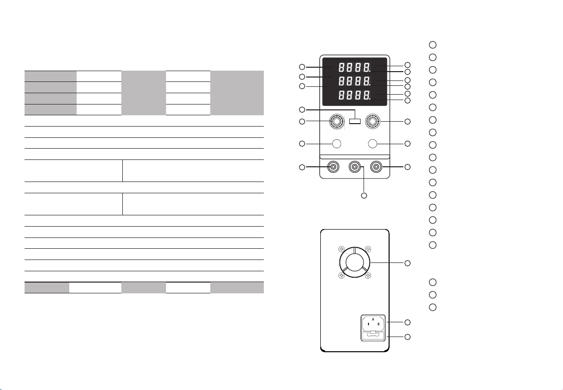
Power button
Voltage adjustable knob
Current adjustable knob
Output push button
Voltage value display
Current value display
Power value display
CV (constant voltage) indicator
CC (constant current) indicator
OCP short circuit indicator
OPN indicator
OVP indicator
Output indicator
20
PANEL INSTRUCTION
1
2
3
4
5
6
7
8
9
10
11
12
13
14
15
16
17
Cooling Fan
Input power socket
Fuse Box
Positive output terminal
Negative output terminal
Grounding bolt
USB charging port
18
19
20
Product Weight:1.12Kg
Fuse Standard
SPS-3005H
0-30V
0-5A
SPS-3010H
0-30V
0-10A
SPS-6005H
0-60V
0-5A
SPS-12003H
0-120V
0-3A
Model Number
Output Voltage
Output Current
T4A/T6A T5A/T8A T5A/T8A T5A/T8A
Output Power 150W 300W 300W 360W
Auxiliary Functions :Output OCP short-circuit protection, USB charging port
Operating Temperature :0℃~40℃ Relative humidity: <80%RH
Storage Temperature: -10℃~70℃ Relative humidity: <70%RH
Constant Voltage Status
Voltage Stability: ≤0.5%+3mV
Load Stability: ≤0.5%+3mV
Ripple Noise: ≤0.5%V P-P
Constant Current Status
Current Stability:≤0.5%+3mV
Load Stability: ≤0.5%+3mV
Ripple Noise: ≤0.5%V P-P
Protection Mode :Short-Circuit, Over-Voltage, Over-Current, Over-Temperature
Display: Four-digit tube, 3-group display on voltage, current, power
Display Accuracy : 0.5%+5digit
Display Resolution :Voltage 0.01V, Current: 0.001A ( >100V at 0.1V ; >10A at 0.01A)
POW ER OU TPU T
CUR REN T VOLTAGE
OV P
OC P
OP N
RM T
C.V
C.C
V
A
W
ON
5
6
7
10
11
17

NOTICE
65
When operating the power supply, please ensure the power
cord is grounded well, if the power socket has no grounding,
you can connect the housing case of power supply with the
wire to ground. Good grounding can prevent power supply
leakage and reduce output ripple interference.
CAUTIONS
1- Please use the power cord which is compliant with the rated
power of this device.
2- Before operating, the device must be grounded in order to
conduct the week leakage current, which caused by the anti-
electromagnetic interference circuit inside the power supply,
into the earth. Otherwise the false leakage might be occurred,
and it can damage the loading deices or decrease the capacity
of anti-interference of this power supply.
3- Once use the power supply to charge the rechargeable battery
(like lead-acid battery), ensure that the positive and negative
poles of the power supply are connected to positive and negative
poles of battery respectively, if not, it might damage the internal
rectifying parts of power supply or the load devices.
4- Do not operate this power supply in the environments such as
flammable, explosive, corrosive gas.
5- Do not block the vent and keep the power supply to be operated
at ventilation environment.
6- Based on the output current value to select the suitable output
wire and keep the connection tightly, to avoid damages on terminals,
load devices, or fire in serious case, please keep contact surface is
clean and rust-free.
7- If malfunction occurred, please consult with your local A/S for
assistance, or return the defective unit for repairing. Since there is
high voltage inside of device (even power off, the high voltage is still
remains in circuit for a certain of period), please do not tempt to repair
or modify by yourself.
8- Make sure the rating voltage, there are two type of input voltage:
AC220V±5% or AC 110V±5%
NOTICE
Make sure input the correct AC voltage, the wrong AC voltage
will damage the device.
FEATURES
1- CV (constant voltage) and CC (constant current) shift mode
automatically, both CV value and CC value can be preset
through encoder, which is convenient to use.
2- Press the OUTPUT push button to activate or exit output of
power supply, and the preset voltage value and current value
will be displayed once exit output.
3- Once there is short circuit in load device, the OCP (short-
circuit protection) will be activated and power supply will exit
output and OCP alarmed twinkly. Once load device is without
short-circuit and press OUTPUT button to restore the output.
This function can protect the load device.
4- The setting voltage and current and actual voltage and
current are displayed in 4-digit.
5- Adopt low noise and thermal controlled cooling fan to
guarantee the suitable operating temperature.
6- CV value and CA value can be stored automatically once
power supply powered off (or shut down), after power on
again, the previous stored values will be used.

87
OPERATION
1-POWER ON
Press the POWER to switch on power supply and display shows
both voltage and current values were set when the device
powered off last time.
2-VOLTAGE SETTING
To rotate the VOLTAGE knob to set the voltage, and the setting
“bit” is popped up, turn the knob clockwise to increase values,
and turn the knob anticlockwise to decrease values. Press the
encoder to shift to the right position, in 3 seconds after voltage
setting, the LED lighting exited and the setting is saved.
3-CURRENT SETTING
To rotate the CURRENT knob to set the current, and the setting
“bit” is popped up, turn the knob clockwise to increase values,
and turn the knob anticlockwise to decrease values. Press the
encoder to shift to the right position, in 3 seconds after current
setting, the LED lighting exited and the setting is saved.
4-OUTPUT PUSH BUTTON
To press OUTPUT push button to activate or exit output of
power supply.
5-OCP SHORT CITCUIT PROTECTION
To press “CURRENT” knob for 3 seconds to activate (or exit)
OCP mode, rotate “CURRENT” to right and OCP indicator will
be lighted up and display showed from 0 to 1, after this to press
“CURRENT” knob for 3 seconds, the setting is saved and return
the original interface, the OCP mode is activated and indicator
lights up. Under this situation, if the power supply detect there
is short-circuit or over current occurred in load device, the power
supply will exit output and OCP indicator twinkled to protect the
load device. You can press OUTPUT to exit OCP mode and
restore output status.
Note: In order to exit OCP mode, once under OCP mode interface
and rotate “CURRENT” knob to left, the OCP indicator turns off
and display from 1 to 0, press “CURRENT” knob for 3 seconds,
the setting is saved and return the original interface, the OCP
mode is exited and indicator lights off.
6-OPN SETTING
Press “OUTPUT” button for 3 seconds to activate (or exit) OPN
mode, and slight press “OUTPUT” button and the display shows
from 0 to 1. After that, press “OUTPUT” button for 3 seconds and
system returns original interface, the OPN mode is activated and
indicator is lighted up.
NOTE: In order to exit OPN mode, once under OPN mode interface,
slightly press “OUTPUT” button and display shows from 1 to 0 and
OPN indicator lights off, after that, press “OUTPUT” button for 3
seconds, the system returns original interface and OPN model is
exited.
7-DISPLAY CONTRAST ADJUSTMENT
Once display shows “OFF”, rotate both “VOLTAGE” and “CURRENT”
simultaneously to activate display contrast adjustment, turning left
to decrease the brightness and turning right to increase brightness.
EXAMPLE
To set the power supply as voltage as 12V and current as 3A.
Operating is as follows:
1-Switch on the power supply
2-Rotate “VOLTAGE” knob to preset the voltage value as 12.00 V.
3-Rotate “CURRENT” knob to preset the current value as 3.000 V.
4-Connect the output terminals of power supply with the loading
device firmly.
5-Slightly press “OUTPUT” push button and “ON” indicator lights
up and power supply activate the output working
6-By press “CURRENT” knob to activate OCP or OPN mode at
desired time.
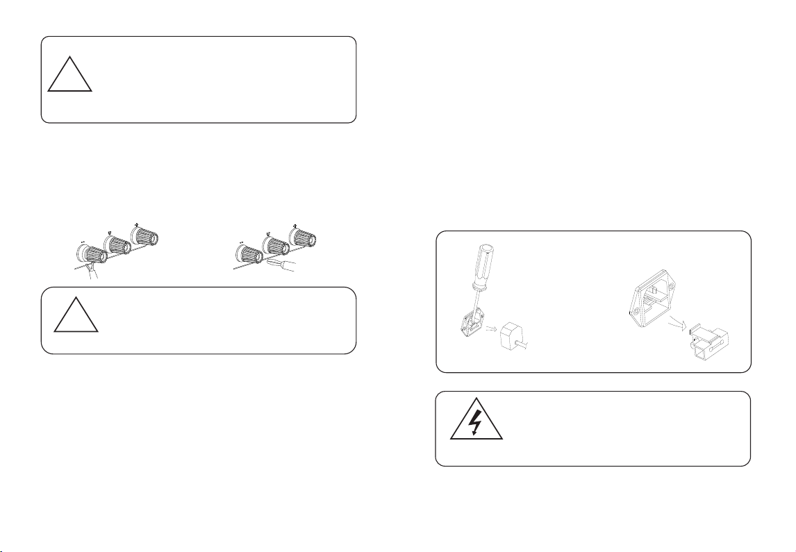
FUSE REPLACEMENT
If the fuse blows, the power supply will stop working.To find and
correct the cause of the blown fuse, then replace it with a fuse of
the same specification.
Fuse cabin is in the power socket
Replace the fuse of same
specification,then put the fuse
cabin back.
HIGH VOLTAGE!
DANGER!
For effective safety protection, it is only necessary to
4replace the fuse of a specific specification. Before
replacing the fuse,the power must be turned off and the
power cord must be unplugged from the power outlet.
automatically switch to constant current mode. The output
current remains stable and the output voltage decreases
proportionally as the load increases further.The conversion of
constant voltage and constant current is indicated by the LED on
the front panel.
CV indicator light is on during constant voltage, CC indicator is
on when constant current.
109
Remove the power plug first,then open
the fuse cabin according to the
illustration.
!
Attention
In actual CV operation, if the load resistance decreases and the
output current increases to the set current value, the power supply
will automatically switch to CC mode.When the load resistance
value continues to decrease, the current will remain at the current
set value.The voltage is proportionally reduced. At this time,
increase the load resistance or increase the current set value to
restore the CV output state.
CONNECT THE LOAD
1. Rotate the terminal knob by turning it counterclockwise
2. Insert the load terminal
3.Turn the terminal knob clockwise
4. Banana plug can be directly inserted into the terminal hole
Improper connection may result in damage to the power
supply and the load connected to the power supply.When
connecting the battery load, do not reverse the polarity of
the “+” and “-" as this may damage the power supply.
CONSTANT VOLTAGE/CONSTANT CURRENT
CHARACTERISTICS
The working characteristics of this series of power supplies are
constant voltage/constant current automatic conversion type,
which can automatically change between constant voltage and
constant current states with load changes. The intersection
between constant voltage and constant current mode is called
conversion point.For example, if the load causes the power
supply to operate in a constant voltage mode, a constant voltage
is output. As the load increases, the output voltage will remain
constant and the output current will increase.When the current
value reaches the set current limit value, the power supply will
!
Attention
This manual suits for next models
3
Table of contents


