NITRON TVT22 User manual

TVT22 FORK CARTRIDGE Installation Instructions

Warnings will be highlighted in boxes like this. This will indicate that your safety is
involved and careful attention should be made to observe these instructions. Severe injury or
fatality may occur if these instructions are not observed.
WARNING
Installation Instructions
This cartridge kit requires special tools and should be installed by an authorised dealer to ensure
optimal function. The front fork is a critical part of the motorcycle and
improper installation could cause serious injury or death.
WARNING
Nitron will not be held responsible for any damage or injury caused through incorrect fitment,
modification or incorrect application of any TVT Fork Cartridge Kits or
related products.
WARNING
If you notice any abnormality in performance or operation, you should stop using the product
immediately and contact Nitron for technical advice.
WARNING
Failure to comply with the installation and maintenance procedures may result in avoidable
damage caused to the shock or motorcycle.
WARNING
Notes and Tips will be highlighted in boxes like this. This will offer important
information regarding procedures or recommendations for ease of installation.
NOTE
Nitron warrant all of its products and accessories against design and material defect for a
period of 1 year from date of purchase. The warranty does not cover any such failure due to
incorrect fitment or use and does not extend to any other part of the motorcycle.
IMPORTANT
Images used in this Instruction Manual are for illustration purposes only, any specific fittings
may differ from your TVT Fork Cartridge Kit.
Please keep the individual specification sheet with the Vehicle Service Manual as this is the
best way to identify your TVT Fork Cartridge Kit.
IMPORTANT
IMPORTANT
2
Introduction
Introduction
Thank you for purchasing a set of Nitron TVT Fork Cartridges. Nitron have invested
heavily in developing the technology, materials and performance of our suspension
components and we are pleased to be able to pass on this experience to our customers. All of our designs
are based on many hours of both real world testing and racing experience. TVT technology has proven to
be extremely versatile and whether you are riding a Superbike on track or adventuring off-road with a Dual
Sport machine you can be sure that your fork cartridge kit has been developed specifically for your needs.
Nitron TVT Adjustable Fork Cartridge Kits offer the same level of improvements in rider control,
performance and comfort that have become the trademark of the Nitron product. The system features a
large bore 22mm shimmed piston which provides significant
improvements in performance over the OEM set up.
Function
The damping system is divided between each fork leg with the right hand side cartridge controlling the
rebound phase and the left hand side compression. This system allows completely independent damping
adjustment making setup both simpler and quicker. Re-valving is also much quicker particularly when a
change is only required to one side of the damping curve.
For ease of use all adjustments are made from the top of the fork, preload is adjusted via a 14mm hex with
each complete turn of the adjuster resulting in 1mm of additional spring preload from a total of 15 turns.
Damping adjustment is adjusted using the supplied tool by turning the 3mm hex in the centre of the fork cap,
there should be at least 25 clicks of adjustment. Careful attention to the design of the adjustment system
results in not only a broad range of adjustment but the click by click adjustment across the range is very
linear making a setup easier.
3

Introduction
4
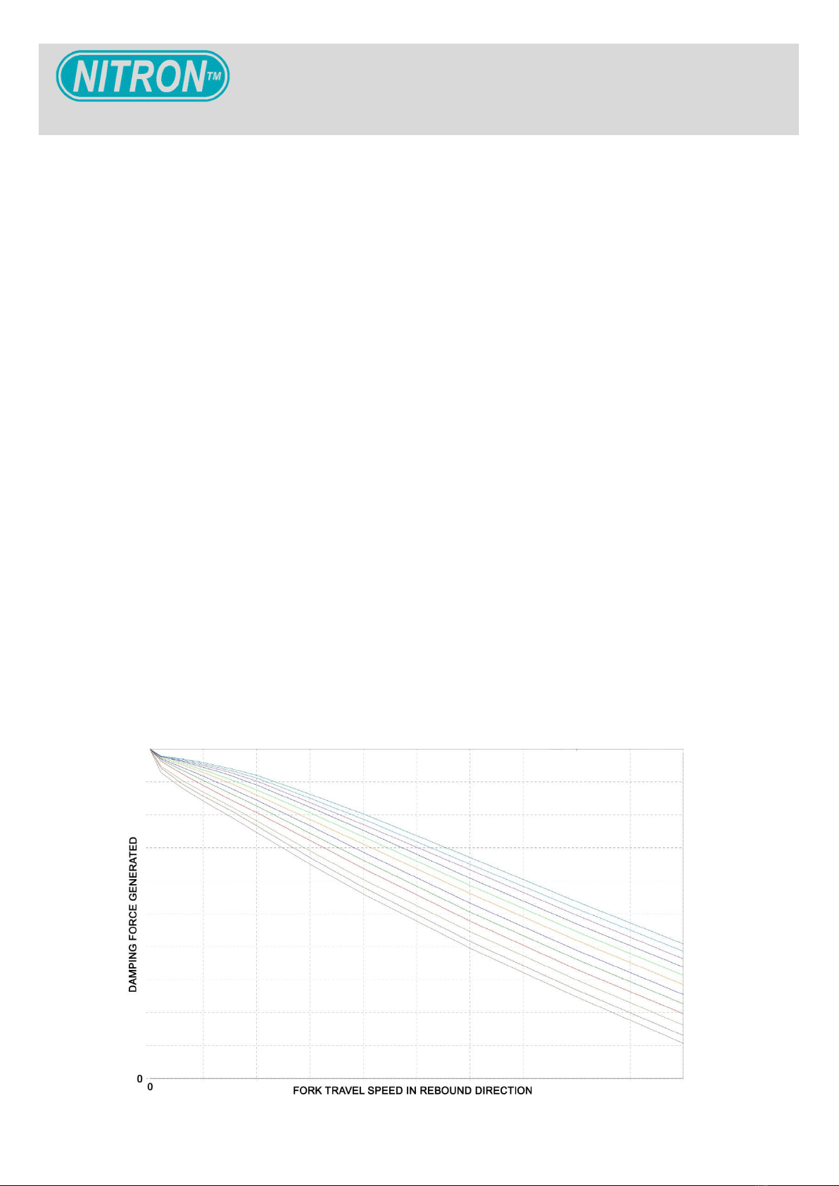
Tri-Valve Technology (TVT)
In addition to the main piston in the compression leg TVT cartridges also employ a third piston which gives a
great deal of flexibility when designing the damping curve for a specific application. This piston also utilizes
shims in much the same way as the main compression piston but with this design the shim stack is
preloaded. During slow to medium speed movements of the fork in compression such as braking or through
undulations in the road the damping is created by the main piston. As the pressure in the compression
cartridge reaches a certain point the preload on the second piston will be overcome and oil can now flow
through the TVT ports reducing overall damping for the higher fork speeds.
The main piston in a TVT fork cartridge can be valved to create firmer damping in the low to mid speed
range of compression velocities giving improved brake support and control of weight transfer leading to
improved rider confidence. With a single compression piston design this would normally result in unwanted
high speed damping forces being generated at higher compression velocities such as square edged bumps
and surface irregularities.
On track, professional riders have praised the system describing new found levels of confidence particularly
during high speed , hard edge bumps which combined with hard braking and cornering forces would
normally unsettle a well damped set up. Likewise on the road this system has allowed new levels of
compliance on bumpy poorly surfaced roads.

Fork Cartridge Diagram
4
1
2
4
5
6
7
8
9
10
12
13
15
17
18
19
20
21 22
No Description
1. Top Cap
2. Preload Cap
3. Spring Spacer Tube
4. Upper Spring Seat
5. Spring
6. Bump Stop Spacer
Tube
7. Plastic Spacer
8. Bump Stop
9. Lower Spring Seat
10. Cartridge Tube
11. Adaptor
12. Aluminium Lock Nut
13. M10 Lock Nut
14. M10 Washer
15. Piston Rod
16. Adjuster Rod
17. Gland
18. Top Out Spring
19. Piston
20. Base Valve
21. Damping Adjuster
22. Preload Adjuster
16
14
3
11

Installation Preparation
6
Installation Preparation
Before commencing with the installation you will need to support the motorcycle with
suitable front and rear stands, ensuring it is on flat, level ground. The front stand should allow the front
wheel to be raised off the floor so it can be removed.
Both fork legs will need to be removed from the motorcycle to perform the installation. It is a good idea to
thoroughly clean the fork legs before proceeding to avoid any contamination later on.
Depending on the amount of use that the fork has had it is recommended to replace the seals and to check
the condition of the bushes. For optimal performance of your fork it is crucial that these are in good condition
and to tolerance. You should also check for any damage to the fork tube coating and if necessary repair or
replace before proceeding any further. Clean the inside of the fork tubes to ensure there is no debris left
inside.
Before removing the fork legs from the yokes loosen the top cap half a turn, this will
make disassembly of the cartridge easier.
NOTE
Do not be tempted to use cheaper and inferior quality seals or bushings as this can
dramatically increase friction in the fork and can even lead to premature wear fork stanchion surface
coatings.
WARNING

Installation Preparation
Description
Piston rod holding plate
Oil level tool
Soft jawed vice
Torque wrench
14mm socket
17mm Spanner X 2
Fork tube removal tool (type ‘C’ installations only – see next page)
Standard Tools Required
Fluids/Grease
Part No. Description
090217 Nitron 02 fully synthetic fork fluid (please see
specification sheet for quantity required)
NTT050473 Molykote 33 White Grease
NTT050476 Loctite 243 Medium Strength Loctite
NTT050477 Loctite 270 High Strength Loctite (type ‘C’ installations
only – see next page)
6
Part No. Description
NTT050392/
NTT050264/
NTT050265.
Fork cartridge top cap tool -33,38 or 41mm PCD.
NTT050268 Piston rod holder.
Refer to the Nitron Fork Tooling Application List for full details.
NOTE
Nitron Specialist Tools

Damper Rod Removal
Damper Rod Removal
Before commencing with the cartridge kit installation if your forks are of the ‘damper rod’ type you will need
to remove these internals from your forks.
Step 1
Undo your OEM top cap and remove the spring and spacer tube if present.
The springs may be under considerable preload so be careful when unscrewing the
top cap to avoid injury. If there is preload adjustment make sure this is backed off first.
WARNING
There will also be a copper crush washer with the bolt, make sure you remove this and
discard it as it may be stuck in the fork bottom.
NOTE
Be careful not to slip and damage the fork tube when removing the dust seal. A plastic
chisel is an effective tool which won’t damage the fork tube.
WARNING
Step 2
Drain the old oil from the fork.
Step 3
Remove the bolt from the bottom of the lower fork tube.
Step 4
The OEM damper rod and top out spring can now be removed.
Step 5
Remove the dust seal.
8
Damper Rod Removal
Step 7
Apply heat around the top of the lower fork tube and then separate the two tubes.
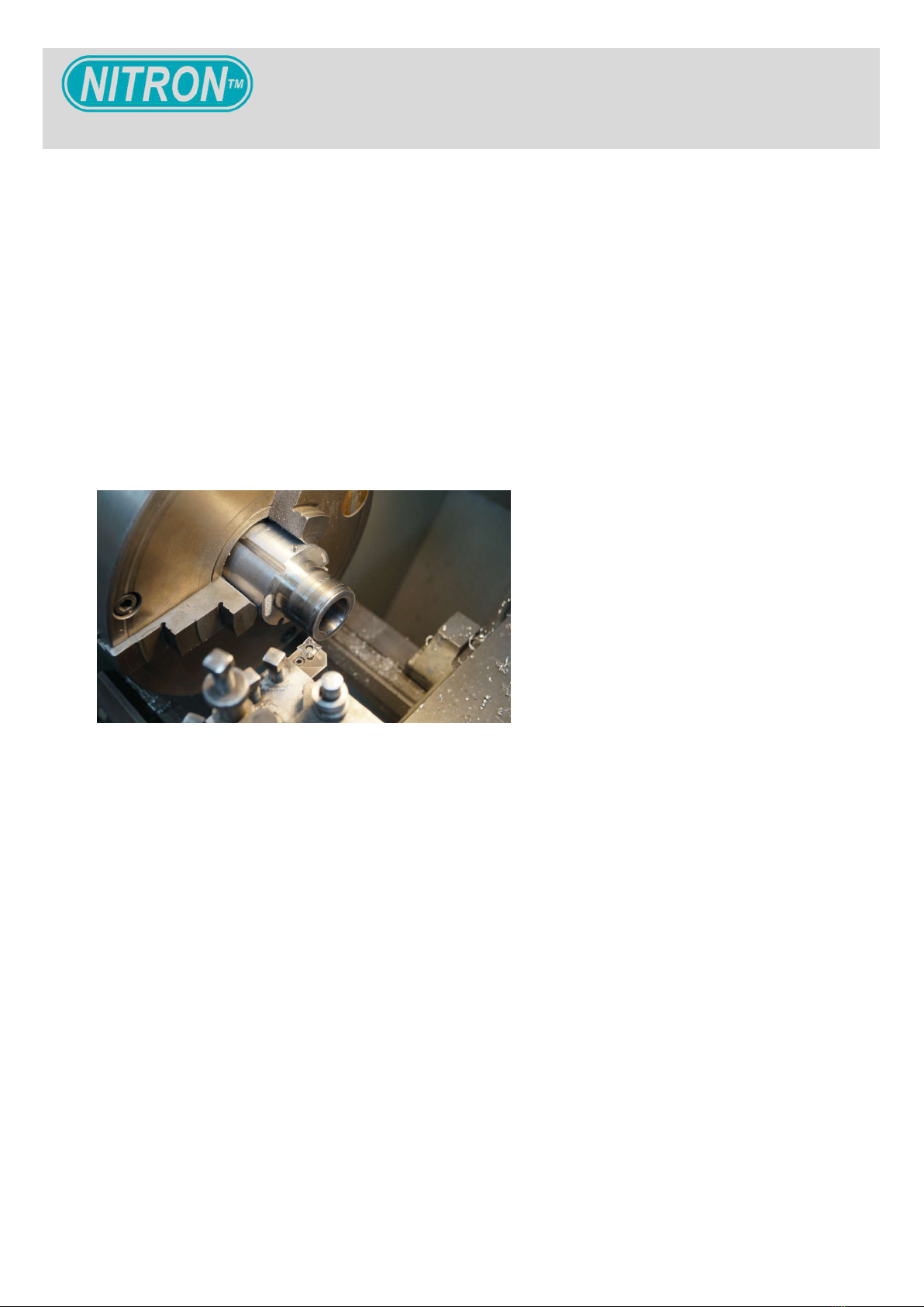
Step 8
Remove the bushes and seals and then part off the very end of the steel tube in a lathe.
Step 9
The OEM damper rod mechanism can then be removed from the fork tube. Remove the bottom out cone
from the very bottom of the lower fork tube.
Step 10
Thoroughly clean the fork tubes. Install the seals and bushes and then insert the inner tube into the outer
tube.
Step 11
Use a seal driver to drive the guide bush and oil seal into place. Replace the circlip and then press the dust
seal back in place.
You are now ready to commence with your cartridge kit installation
Step 6
Remove the circlip.
9

Assembly Instructions
Assembly Instructions
Your cartridge will arrive partially assembled. Unscrew the top cap from the piston rod and then remove the
spring spacer tube, upper spring seat and spring. Remove the two locknuts and washer from the piston rod,
bump stop spacer tube, plastic spacer, bump stop and lower spring seat.
Your cartridge kit splits the functions of compression and rebound damping into separate
fork legs. The rebound cartridge should be installed in the right hand fork leg and the
compression cartridge in the left hand leg. Be careful not to mix the two cartridges up, it is
advisable to work on one fork at a time.
WARNING
Step 1 Install The Cartridge Into The Fork
Install the cartridge into the fork. Apply Loctite 243
medium strength threadlock to the bolt with a new
crush washer and tighten the cartridge to the fork
bottom. Refer to your owners manual for the correct
torque setting.
Step 2 Filling The Fork With Fluid
Pour approximately half of the bottle of suspension
fluid into the fork leg making sure that it easily
covers the top of the cartridge body tube.
For the best damping performance it is essential to use Nitron 02 suspension fluid.
WARNING
10
Assembly Instructions
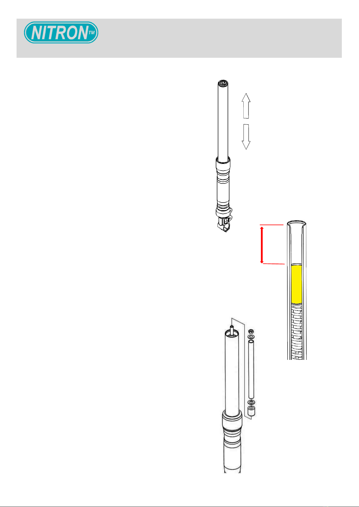
Step 3 Bleeding Air From The Fork
Work the upper fork tube up and down at least
fifteen times to bleed any air that may be trapped
between the two fork tubes.
Step 4 Bleeding Air From The Cartridge
Work the piston rod up and down at least fifteen
times to bleed the air from the cartridge.
11
Step 5 Setting The Oil Level (Air Gap)
Push the inner fork tube and the piston rod all the
way down. Using a suitable oil level tool add or
remove oil to obtain the specified oil height (refer to
the specification sheet for your model specific air
gap measurement). The quoted oil height is the
measurement from the upper edge of the fork tube
to the surface of the oil.
Step 6 Lower Spring Seat Installation
Install the lower spring seat onto the piston rod.
Make sure this piece is installed in the correct
orientation.
Step 7 Bump Stop Installation
Install the bump stop, plastic washer, bump stop
spacer tube, M10 washer and M10 locknut.
X

Final Assembly Instructions
Step 8a Setting The Lock Nut
Set the correct position of the lock nut, refer to the
specification sheet for your model specific
measurement. The measurement should be taken
from the end of the piston rod to the top of the lock
nut.
12
Step 8b Setting The Lock Nut
Install the aluminium lock nut and tighten securely
against the steel M10 lock nut.
X
It is imperative that the locknut is in the correct position to ensure the correct function of the fork
cartridge. There should be between 25 and 30 clicks of adjustment, if there are more or less
than this the lock nut is in the wrong position.
WARNING

15
Step 9 Installation Of The Spring Hardware
You are now ready to close the fork. Screw
NTT050268 – piston rod holder onto the end of the
piston rod. Install the spring, upper spring seat,
spring spacer tube and spring preload cap. Pull the
piston rod upwards and then insert a 17mm
spanner through the window in the spring preload
cap. You can now remove the piston rod holder
tool.
Final Assembly Instructions
Step 10 Top Cap Installation
Screw the top cap onto the piston rod. Tighten the
top cap to the piston rod using a 14mm socket to
20N/m. A plastic socket insert is recommended to
prevent marring the aluminium.

Assembly Instructions
14
Step 11 Top Cap Tightening
Remove the 17mm spanner and then pull the inner fork
tube up and screw the top cap into it. Tighten to 10N/m
using the top cap specific tool for your model (see
specification sheet).

Assembly Instructions
Do not force the adjuster at either end of its adjustment range as this may damage the
internal components.
WARNING
Spring preload is adjusted by turning the 14mm hex,
every complete turn of adjustment equals 1mm of spring
preload. There are 15 turns of adjustment in total and the
setting is referenced as the number of turns from the fully
anti-clockwise position. Adjusting spring preload will
change the amount of initial force required to compress
the springs a given distance in relation to their rate. This
will effectively raise (more preload) or lower (less
preload) the front of the bike thus changing the angle of
the fork and the bikes attitude.
15
Setup
Set the compression and rebound damping adjusters to
the baseline settings specified in your model specific
specification sheet. Adjustment is made by screwing the
adjuster clockwise to its full hard position and then
counting the clicks backwards from this point.

16
Table of contents


