Nittan CKLD-KPT2 User manual

Instruction Manual
Beam Type Smoke Detector
Thank you for purchasing our product.
Please read through the instruction manual before use.
Keep this manual in an easily accessible place for future
reference.

2
Handling Instructions ·············································· 3
Names of Parts ····················································· 5
Installation ··························································· 7
Wiring Connection ················································· 9
Adjustment of Light Axis (Transmitter and Receiver) ···· 10
Adjustment of Receiving Light Intensity (Receiver) ······ 11
Sensitivity and Response Time ······························· 14
Sensitivity Test ···················································· 14
Compensation and Fault Signal ······························· 15
Sensitivity Compensation ······································· 15
Test Function ······················································ 16
Maintenance ······················································· 17
Indicator ····························································· 17
Specification ························································ 18
Table of Contents
3
For Your Safety
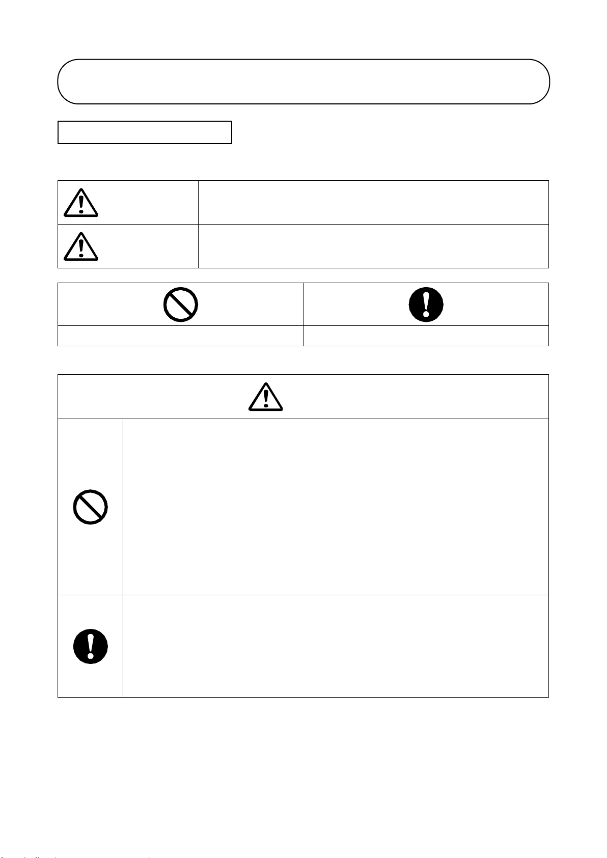
The criteria of the Danger, Warning and Caution markings are as follows.
Warning
There is a risk of endangering the health or life of the user, or
causing a significant damage to the product if the product is
mishandled.
Caution
There is a risk of causing minor injuries, damage to the product,
or a trouble to the product if the product is mishandled.
Action Prohibited
Action Mandated or Directed
Warning
〇Do not get the equipment wet or touch it with a wet hand.
It may cause electric shock or system trouble.
〇Do not use the equipment in a location where operating temperature
exceeds its range (-10 to +50°C) or where explosive gas or corrosive gas
is generated.
It may cause the equipment trouble or fire ignition.
〇Do not use the equipment in a location with high humidity, or where
condensation, steam, or oily smoke is generated.
It may cause electric shock or system trouble.
〇Do not disassemble or modify the equipment.
It may cause electric shock or system trouble.
〇 Make sure to connect to each terminal correctly, according to rated
capacity and polarity.
Otherwise it may cause the equipment trouble or fire ignition.
〇If work at height is involved, make sure to secure scaffolding for safety
to prevent falls.
There is risk of falls or falling objects.
Handling Instructions

4
Warning
〇Make sure to turn the power off before commencing any wiring work.
Otherwise it may cause damage to the equipment.
〇 Avoid installing the product in any location where it can be easily
touched by accident.
It may cause injury.
〇Ensure to fix the product securely.
Otherwise it may cause falling.
Important
1)Notes in installation
・Contact your distributor or contractor for the installation of the product.
・Any work at height must be carried out by no less than 2 persons in order to prevent
falling accidents.
・Use the Remote Station(LP05/LP04) in combination with the Detector.
・Avoid locations where the Receiver is exposed to direct sunlight.
・Avoid locations where the Receiver is exposed to an intense light source (more
than 5000 lux), light beam, or strobe light. Optional shading hood (KLD-14) is also
available.
・Secure the space of approximately 1 square meter around the Detector and the
Remote Station, for maintenance and adjustment after the installation.
・In the event of installation in places where the Detector may be hit by a ball such
as a school gymnasium, use the optional protector (KLD-15).
2)Notes in operation
・Place the monitoring switch of Remote Station back to the normal position. If the
switch is shifted to the monitoring side, normal monitoring is not available.
3)Notes in maintenance
・Antifog coating is applied to both the Transmitter and Receiver lenses. For
cleaning, gently wipe off with a dry soft cloth to avoid damage. Do not use thinner
or other solvents.
Handling Instructions

5
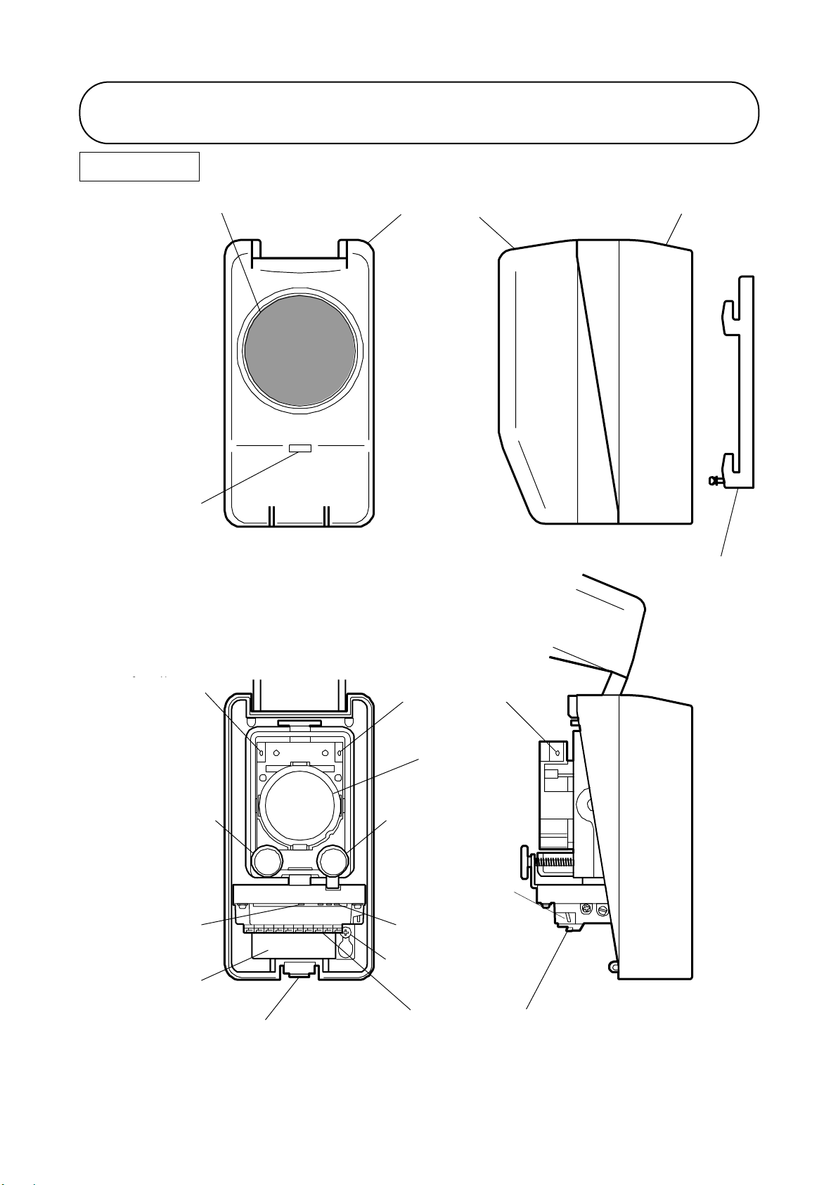
Transmitter Upper figure: Cover closed Lower figure: Cover opened
Names of Parts
Collimation Dial Y
(Vertical)
Lock Tab
Lens
Collimation Hole
Collimation Hole
Wiring Hole
Wiring Terminal
Lens Cover
Cover
Body
Base
Detector Fixing
Screw
Power Indicator
Power Indicator
Collimation Dial X
(Horizontal)
6
Receiver Upper figure: Cover closed Lower figure: Cover opened
Names of Parts
調整スイッチ
Collimation Dial Y
(Vertical)
Lock Tab
Lens
Collimation Hole
Collimation Hole
Wiring Hole
Light Intensity
Indicator
Status Switch
Lens Cover
Cover
Body
Base
Alarm Indicator
Alarm Indicator
Collimation Dial X
(Horizontal)
Wiring Terminal
Detector Fixing
Screw

7
※ベース固定ねじ(なべ小ねじ
M4×10)は別途ご用意くだ
さい。
掛け部
ベース
通線孔
感知器固定ねじ
2
3
4
1※
1. Pay attention to the vertical direction of the Base and fix it to the
wall. (Detector Fixing Screw to be on the bottom).
2. Pull out Wiring cable from the Wiring Hole.
3. Do not tighten the Detector Fixing Screw until the Detector is
mounted onto the Base.
4. Put the Detector onto the Base and slide it downward, as shown
in the figure. Four hooks on the Base are to be slotted into the
slit provided on the back side of the Detector, in order to be
temporarily fixed.
Base Mounting Dimensions (mm)
Installation
Wiring Hole
Base
Detector Fixing Screw
Wiring Hole
Base
Detector Fixing Screw
Hook
※Screws for fixing the base
(Pan-head screw M4x10)
to be prepared separately.

8
5. Press the Lock Tab, open and move the body cover upward. The
cover can be held at 2 positions to make the installation easier.
6. Fasten the Detector Fixing Screw next to the Wiring Hole.
Ensure that the head of the screw is positioned at the specific
position of the main body. Fasten the Detector Fixing Screw to
secure the Detector to the Base. When detaching the Detector,
loosen the Detector Fixing Screw and slide the Detector upward.
〇Set the Status Switch of the Receiver to “CAL” position before
power up.
When the Detector is powered up while the Status Switch is at the
“NORM” position, the Detector may go into alarm.
〇Please be aware that the switch would go back to “NORM”
position when the Detector cover is closed.
〇The mounting method for both the Transmitter and the Receiver
are the same.
Installation
Detector Fixing Screw
Cover holding position 1
Cover holding position 2
Hook

9
Control
Panel I+
F
FL C Lx
LD+Lin Cin Lx
Remote
Station
L
C
T
K
L
C
T
K
SL SC SLSC
Receiver Transmitter
K C L
End of line device
As required
1.Use dedicated Remote Station LP04 or LP05.
2.The number of the Detector and the Remote Station connected to
a zone is 3 sets at maximum for LP04, and 1 set for LP05.
3.In case of using LP05, do not connect any other detector in the
same zone.
4.The line between L and C of the Detector is polarity insensitive.
The other terminals are polarity sensitive.
5.Ensure to connect the EOL device accompanied with the Remote
Station in the line between L and C, and C and K of the Receiver.
6.In case of requirement of taking trouble status of CKLD-KPT2 by
compatible control panel through the remote station, make wiring
“Lx” between panel and remote station, and wiring “K” between
receiver and remote station respectively.
Wiring Connection
Wiring Example
LP05
10
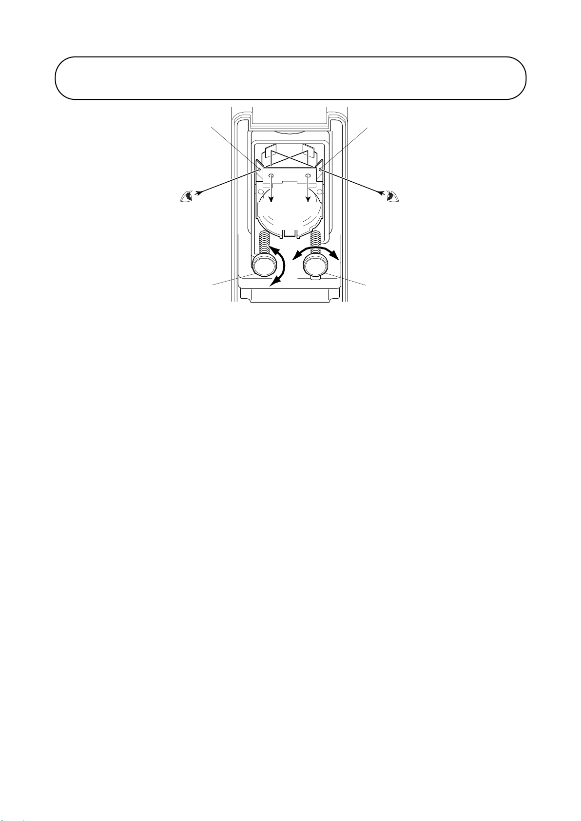
Collimation Dial
Two Collimation Dials X and Y are provided to adjust the light axis.
Look into one of the Collimation Holes provided above the lens to collimate
the opposed unit. Turn the Collimation Dial, until the opposed unit can be
seen in the center of the hole.
Vertical adjustment
Turn the Collimation Dial Y to adjust the light axis in a vertical direction.
The degree range of movement on “Y” dial is plus-minus 10 degrees. One
full turn of dial corresponds to approximately 1 degree change.
Horizontal adjustment
Turn the Collimation Dial X to adjust the light axis in a horizontal direction.
The degree range of movement on “X” dial is plus-minus 10 degrees. One
full turn of dial corresponds to approximately 1.7 degree change.
Adjustment procedure
1.Adjust the light axis of the Transmitter.
2.After the light axis adjustment is completed, close the main cover
immediately.
3.Adjust the light axis of the Receiver.
4.After the light axis adjustment is completed, adjust the receiving light
intensity next.
Adjustment of Light Axis (Transmitter and Receiver)
Collimation Dial Y
Collimation Dial X
Collimation Hole
Collimation Hole
U
D
L
R
Collimation
Axis

11
FIRE
L L C C T K K KC SL SC
LED flickers
while calibration
Monitor for Cal
Lo w O K High
Cal NORM Cal
L
M
S
Alarm Indicator
(Flashing during calibration)
Light Strength Indicator
Distance Selection SW
Light Strength Adjustment VR
Status Switch
〇Ensure that the cover of the Transmitter is closed completely
before adjusting the receiving light intensity.
If the cover is opened, it is not possible to adjust the receiving light
intensity.
1.Confirm that the control panel is powered off (i.e. the Detector is
not powered).
2.Open the cover of the Receiver, and move the Status Switch from
“NORM” to “CAL” position.
3.Turn on the power of the control panel to power the Detector.
Confirm that the Alarm Indicator of Receiver blinks.
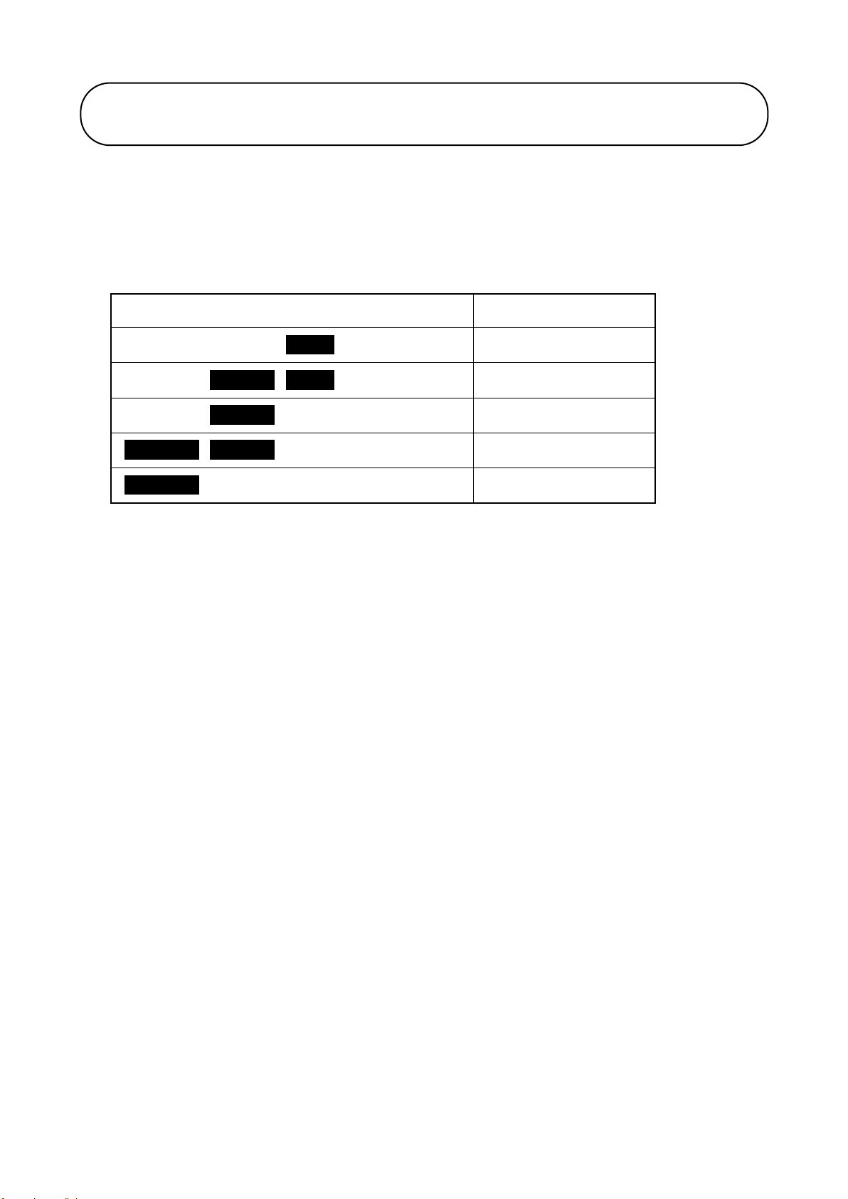
4.Set the Distance Selection Switch according to the table below.
Distance Selection Switch
Distance between Transmitter
and Receiver
Short
5m to less than 15m
Medium
15m to less than 40m
Long
40m to 100m
Adjustment of Receiving Light Intensity (Receiver)
Light Intensity Indicator
Alarm Indicator
Status Switch
Distance Selection Switch
Light Intensity Adjustment Volume
CAL
CAL
12
5.Turn and adjust the Light Intensity Adjustment Volume, looking at
the Light Intensity Indicator, so that only the green indicator
blinks.
Light Intensity Indicator
Light Intensity Level
Orange Green Red ------ Blinking
Too high
Orange Green Red ------ Blinking
Slightly high
Orange Green Red ------ Blinking
Adjusted
Orange Green Red ------ Blinking
Slightly low
Orange Green Red ------ Blinking
Too low
In spite of adjusting the Light Intensity Adjustment Volume to
maximum, if the orange indicator still blinks, the adjustment of light
axis or the setting of Distance Selection Switch may be
inappropriate.
Check the adjustment of light axis and the setting of Distance
Selection Switch.
In spite of adjusting the Light Intensity Adjustment Volume to
minimum, if the red indicator still blinks, the setting of Distance
Selection Switch may be inappropriate.
Check the setting of Distance Selection Switch.
6.Confirm that received light intensity level is adjusted (i.e. only the
green indicator is blinking). Put the Status Switch back to the
“NORM” position, and the adjustment of received light intensity is
completed. Close the cover immediately after the completion.
7.When the Status Switch is back to “NORM” position, the Detector
starts its initialization that takes 3 minutes. The Alarm Indicator of
the Receiver blinks during the initialization. The indicator turns off,
when the initialization completes and the Detector goes back to
the normal monitoring condition.
Adjustment of Receiving Light Intensity (Receiver)
13
8.After adjusting the Detector, the state of detector can be
monitored by using the Remote Station for Beam Detector. For
the details of monitoring, refer to the instruction manual of
Remote Station for Beam Detector LP04/ LP05.
〇Make sure that the voltage between K and C during monitoring is
within the following range, and not the range specified in the
instruction manual of the Remote Station.
Voltage range for monitoring
Approx. 2.08V to 2.23V
〇If the main cover is left open longer than 10 seconds after the Status
Switch has put back to the “NORM” position, put the Status switch
back to “CAL” position and perform the operation from 5. above again.
〇Keep clear the monitoring area (light axis) during initialization.
〇Sensitivity test must not be conducted during initialization. Make sure
that the Alarm Indicator of the Receiver finishes blinking before
sensitivity test.
Adjustment of Receiving Light Intensity (Receiver)

14
The sensitivity of detector (obscuration rate) and response time are
shown in the following table.
Distance between
Transmitter and Receiver
Sensitivity of activation
(central value)
Response
time
5m to less than 15m
30 %
4-10 sec
15m to less than 40m
40 %
4-10 sec
40m to 100m
65 %
4-10 sec
Put the light obscuration filter test unit (NKL-F2), which is sold
separately, just in front of the lens of Receiver to perform Activation
/Non-activation test. Use the filters in the test according to the
following table.
Distance between
Transmitter and Receiver
Activation test
Non-activation test
5m to less than 15m
40 % filter
20 % filter
15m to less than 40m
50 % filter
30 % filter
40m to 100m
80 % filter
50 % filter
Make sure that the Detector is activated within 30 seconds in
Activation test, and is not activated for 2 minutes in Non-activation
test, after placing the filter.
Sensitivity and Response Time
Sensitivity Test

15
1. The Detector performs compensation process for the slow change
of received light intensity which is caused by the contamination of
the lens or shifting of light axis. In the monitoring condition, the
Detector regularly checks if light intensity received by the Receiver
is appropriate. If specified light intensity cannot be received,
compensation process is performed to compensate light intensity.
2. The Detector sends a fault signal (short circuit between K and C)
to the Remote Station, if the light intensity continues to be less
than 43% or more than 130% of the initial value for 12 hours or
more.
Cause of Fault
Countermeasures
Light axis is misaligned
Adjust the light axis and the receiving light
intensity.
(Refer to “Handling Instructions” on page 4)
Lens cover is contaminated
Clean the lens cover and adjust the
receiving light intensity.
(Refer to “Handling Instructions” on page 4)
〇 After readjusting the light axis and the receiving light intensity,
in order to update the internal status of detector, make sure to
restart the detector. Press and hold the reset switch of Remote
Station for 5 seconds or more, after the initial setting is completed
(i.e. when approx. 3 minutes pass after the Status Switch is placed
at the “NORM” position).
(If restarting the detector cannot be easily done, please wait for the
automatic update of internal status, which is performed 20 minutes
after the completion of initial setting)
The sensitivity of detector is compensated also if the received light
intensity is reduced to less than 50 % of initial setting value. If the
received light intensity continuously decreases, the Detector goes
into alarm at the specific sensitivity level.
Compensation and Fault Signal
Sensitivity Compensation

16
The remote test function is supported by using Remote Station for
Beam Detector (LP04/ LP05) to connect the Detector to P-type
control panel. Test is remotely performed by operating the test
switch of the Remote Station. Refer to the Operation Instruction
Manual of the Remote Station for test method.
Test Function
17
Fire alarm systems are essential for providing early detection and
warning in the event of fire in order to save lives and properties and
minimize damage. After installed, periodical maintenance is
necessary to keep the facilities in proper condition.
Important
〇Note in cleaning
Antifog coating is applied to both lenses of the Detector. For cleaning, gently wipe off
with a dry soft cloth to avoid damage. Do not use thinner or other solvents.
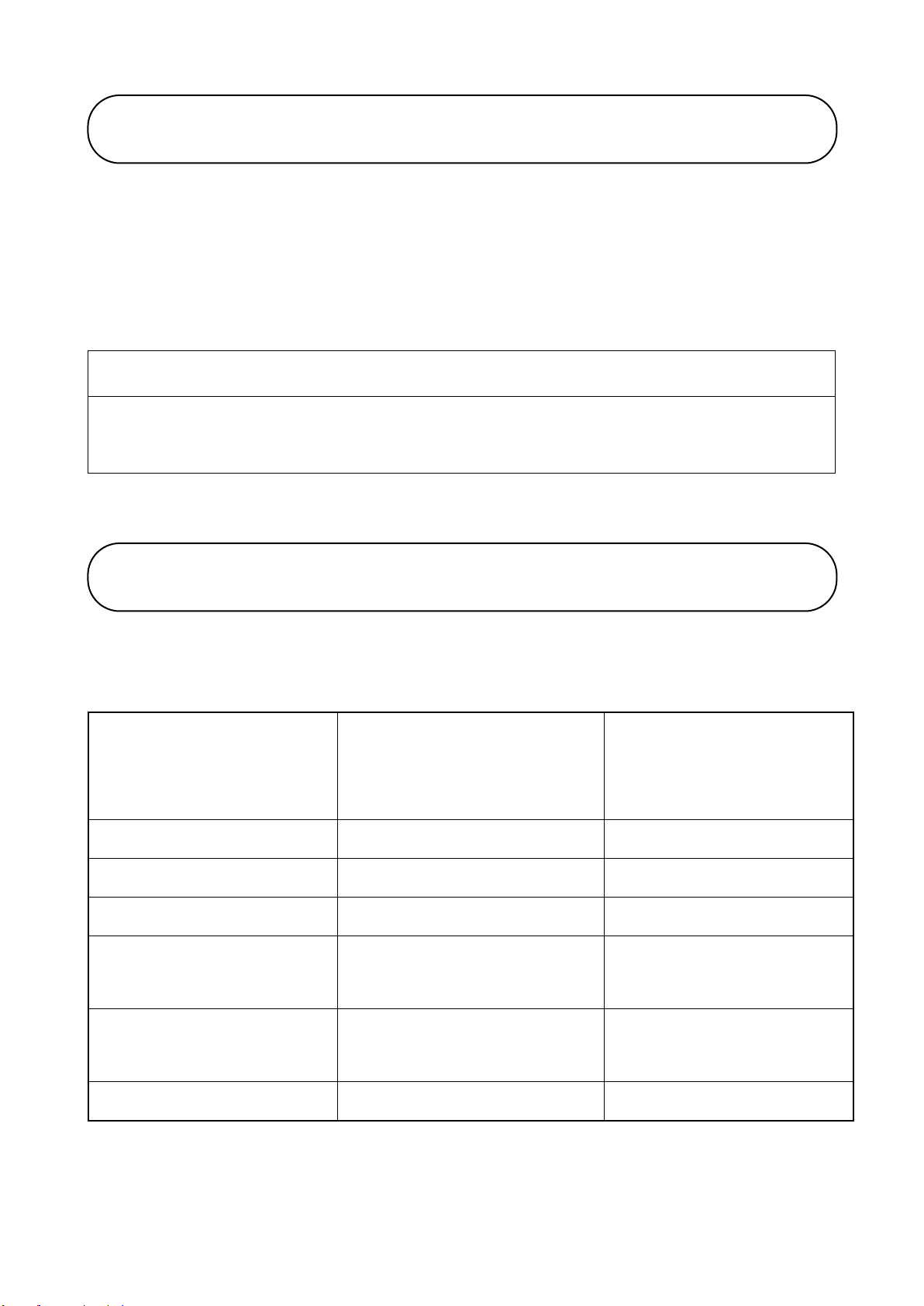
Each state of the indicator of Receiver is as follows.
State of the Detector
Receiver
Light Intensity
Indicator
Receiver
Alarm Indicator
Adjustment
Blinking
Blinking
Normal monitoring
Off
Off
Fire
Off
On
Low received light
(12 hrs or more)
Off
Off
High received light
(12 hrs or more)
Off
Off
No received light
Off
On
Maintenance
Indicator

18
Classification
Beam type smoke detector (with test function)
Model
CKLD-KPT2
Allowable Distance
5m to 100m
Sensitivity
Distance Sensitivity
5m to less than 15m :30%
15m to less than 40m :40%
40m to 100m :65%
Rated Current/ Voltage
L-C:Fire Nominal Voltage DC 24V
Monitoring current 760μA
Alarm current 65mA
K-C:Fault Nominal voltage DC 24V
Alarm current 65mA
T-C:Test Nominal voltage DC 24V
Alarm current 100mA
Indicator
Transmitter:Power Indicator(red LED)
Blinking in the monitoring state
Receiver: Alarm indicator(red LED)
Turning on in the alarm state
Other functions
Adjustment of receiving light intensity
Sensitivity compensation
Fault signal output
Terminal
Transmitter SL & SC (Transmission signal)×1 for each
Receiver L & C (Fire signal)×2 for each
T(Test signal)×1
K(Fault signal)×2
KC (Fault signal)×1
SL & SC (Transmission signal)×1 for each
Compatible control panel
1PM2, 1PM3
Remote Station
LP04/LP05
Temperature & humidity
-10℃ to 50℃
Relative humidity 0% to 95%(no condensation)
Note: This product should not be installed in excessive humid
or condensing conditions.
Weight
Transmitter Approx. 500g (including the base)
Receiver Approx. 520g (including the base)
54-5, 1-chome, Sasazuka, Shibuya-ku, Tokyo 151-8535, Japan
TEL: 81-3-5333-7021 / FAX: 81-3-5333-8615
https://www.nittan.com/english/
Specification
20.11B
Table of contents
Other Nittan Smoke Alarm manuals

Nittan
Nittan EVC-PY-IS User manual

Nittan
Nittan ST-P-AS User manual

Nittan
Nittan EVCA-P User manual

Nittan
Nittan EVC-P User manual

Nittan
Nittan Evolution-Advanced EV-DP User manual

Nittan
Nittan EVA-PYH User manual

Nittan
Nittan ST-P-OM User manual

Nittan
Nittan evolution EVC-P User manual

Nittan
Nittan EVA-PYH User manual

Nittan
Nittan Evolution EVC-DP User manual


