Nittan ST-P-AS User manual
02
NISM/STPA/02
DATE:
PAGE:
No:
ISSUE:
of17
ST-P-AS
ANALOGUE-ADDRESSABLE
PHOTOELECTRIC SMOKE SENSOR
INSTRUCTION MANUAL
MARCH 2001
NITTAN (UK) LTD - BRINGING STYLE INTO FIRE DETECTION SYSTEMS
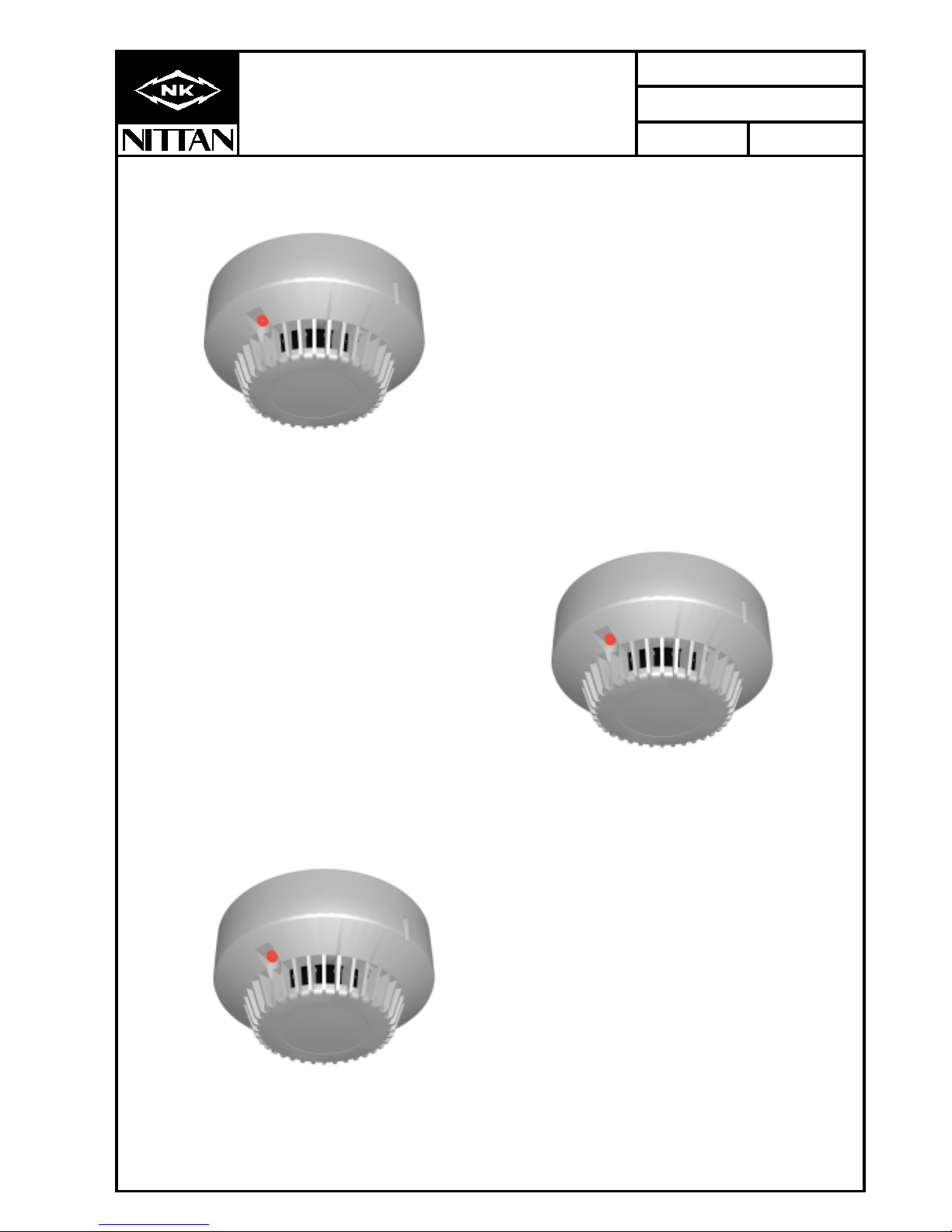
The new ST-P-AS photoelectric smoke sensor forms part of a brand new
range of analogue addressable fire detectors from Nittan (UK) Ltd called
SENSORTEC-ANALOGUE.
The ST-P-AS is a low cost, elegantly designed, low profile sensor which
is aesthetically pleasing, thus enabling it to blend unobtrusively into
modern working environments.
The ST-P-AS features the very latest technological advancements,
increasing reliability and performance.
The ST-P-AS is compatible with our existing 'AS' protocol and is
compatible with leading panel manufacturers.
SENSORTEC-ANALOGUE.......
From world leaders in SENSOR TECHNOLOGY
comes SENSORTEC.........

02
NISM/STPA/02
DATE:
PAGE:
No:
ISSUE:
of27
ST-P-AS
ANALOGUE-ADDRESSABLE
PHOTOELECTRIC SMOKE SENSOR
INSTRUCTION MANUAL
MARCH 2001
Section 1 - INTRODUCTION
The ST-P-AS is an attractively-styled, low cost, low
profile photoelectric smoke sensor for use with Nittan
'AS' protocol control panels. This sensor is virtually
identical in function to our 2KH-AS/2KH-AS2LR sensor
and can therefore be used as a direct replacement.
The ST-P-AS has a chemically etched, stainless steel
insect screen therefore reducing the ingress of insects
and airborne contaminants.
The sensitivity of the ST-P-AS is easily confirmed in the
field, using the TT3 or TT4* electronic tester.
* Available early 1998.
ST-P-AS features:
* Optical detector, detecting visible particles
of combustion
* Low profile, stylish appearance
* Supplied with protective dust cover,
(remove during commissioning)
* Low monitoring current
* Integral LED fire alarm indicator
* Remote indicator output on standard models
* Easy to disassemble and reassemble for cleaning
* Uses STB-4 & earlier RB-3/RB-6 Bases
* Manufactured to meet the requirements of
EN54 Part 7.
CONTENTS:-
Section 1 - Introduction - Page 1
Section 2 - Operation - Page 2
Section 3 - Sensor Models - Page 3
Section 4 - Base Models - Page 3
Section 5 - Installation - Page 3
Section 6 - Maintenance &
Cleaning - Page 4
Section 7 - Specifications - Page 6
Section 8 - Environment
Parameters:- - Page 6
- Temperature - Page 6
- Humidity - Page 6
Section 9 - EMC - Page 6
Section 10 - Connections - Page 7
Section 11 - Dimensions - Page 7

02
NISM/STPA/02
DATE:
PAGE:
No:
ISSUE:
of37
ST-P-AS
ANALOGUE-ADDRESSABLE
PHOTOELECTRIC SMOKE SENSOR
INSTRUCTION MANUAL
MARCH 2001
Section 2 - ST-P-AS OPERATION
The ST-P-AS utilises the light scatter sensing
principle, using an LED and photodiode in a light proof
chamber. The LED pulses infrared light into the
smoke chamber, the photodiode being positioned
such that a minimum of light is normally received. As
the smoke enters the sensor the amount of scattered
light increases. This change is detected by the
photodiode and is amplified before being processed
and transmitted to the control panel
Section 3 - SENSOR MODELS
The ST-P-AS photoelectric smoke sensor is supplied,
as standard, with three terminals.
The ST-P-AS has the facility to activate a remote LED
indicator or auxiliary function, as standard.
The terminals on the ST-P-AS sensor head are
configured as follows:-
Terminal 3 = -VE 3 mA aux output
Terminal 1 = Sig + (+VE) positive in/out
Terminal 6 = S- (-VE) negative in/out
Section 4 - BASE MODELS
STB-4 Base: having 4 terminals, for standard
use with ST-P-AS sensor including the auxiliary
output function.
Section 5 - INSTALLATION
In normal use, the ST-P-AS sensor will be installed at
ceiling level. Pass the field wiring through the cable
hole in the centre and from the rear of the base. Offer
up and affix the base to the ceiling or conduit fitting
with screws via the base mounting holes. Consider
visibility and orientation of the sensor's integral alarm
LED indicator when mounting the base. Connect the
field wiring to the base terminals, as detailed on page
6 making sure the wiring does not obstruct fitting of
the detector head. Fit the sensor head by inserting it
into the base and turning clockwise until the notch in
the detector rim aligns with base locking screw.
Fit the plastic dust cover supplied over the sensor to
keep out dust etc, until the system is commissioned.
If the dust cover is not fitted and the environment is
slightly dusty, such as when building work is being
completed, for example, problems of false alarms are
likely to occur after commissioning unless cleaning of
the sensor is undertaken. At commissioning, the dust
cover should be removed and discarded.
NOTE: THE PLASTIC DUST COVER MUST BE
REMOVED FROM THE SENSOR IN ORDER FOR
THE SENSOR TO FUNCTION CORRECTLY.
Section 6 - MAINTENANCE AND
CLEANING
Maintenance:
The ST-P-AS sensor is a high quality product engi-
neered for reliability. In order to obtain optimum per-
formance, periodic maintenance is required as a dirty
detector is more likely to cause a false alarm.
Servicing:
Servicing of the system should be carried out in accord-
ance with the requirements of BS 5839 Part 1, Fire
Detection and Alarm Systems for Buildings: Code of
Practice for System Design, Installation and Servicing.
The maintenance procedures described below should be
conducted with the following frequency:
One month after installation:- Routine Inspection
and every 3 months
after.
Every 6 months:- Operational Test
Every 12 months:- Functional Test and
Clean
All above frequencies of maintenance are dependent on
ambient conditions.
Routine Inspection
i) Ensure the sensor head is secure and undamaged.
ii) Check the smoke entry apertures are in no way
obstructed.
iii) Ensure the surface of the sensor’s outer cover is
clean. If there are deposits due to the presence of oil
vapour, dust etc, then the sensor should be cleaned in
accordance with the cleaning instructions detailed later
in this manual. It may be advisable to ensure that such
cleaning is conducted regularly in the future.
iv) Ensure no equipment which may generate combus-
tion products or fine airborne particles, has been in-
stalled in the vicinity of the detector since the last
routine inspection. If such equipment has been in-
stalled, then you should notify the Fire Safety Officer or
other competent authority that it’s presence may
cause false alarms.
Operational Test
The purpose of the Operational Test is to confirm the
sensor’s correct operation in response to a smoke
condition.
i) Take any necessary precautions at the control panel
to limit the sounding of the alarm sounders/bells and
any fire service summoning device.
02
NISM/STPA/02
DATE:
PAGE:
No:
ISSUE:
of47
ST-P-AS
ANALOGUE-ADDRESSABLE
PHOTOELECTRIC SMOKE SENSOR
INSTRUCTION MANUAL
MARCH 2001
ii) Introduce a discrete amount of smoke into the
sensor head, using NID-T2 Smoke Test Head or
equivalent. Check that the detector gives an alarm
condition within 15 seconds. Check the LED indicator
on the ST-P-AS sensor illuminates and any remote
indicator LED fitted also illuminates.
iii) After the sensor has given the alarm condition, reset
the sensor from the control panel. It may be necessary
to allow a short time to elapse before resetting the
detector, to allow any residual smoke from the test, to
disperse.
iv) Before proceeding to the next detector, ensure that
the sensor previously tested, does not re-operate due to
the presence of residual smoke.
Functional Tests:-
The ST-P-AS may be tested on the TT3 or TT4*
transmission tester, please refer to the instruction
manual for the testers as follows:-
TT3 = NISM/TT3/01 April 1993
TT4 = Available early 1998
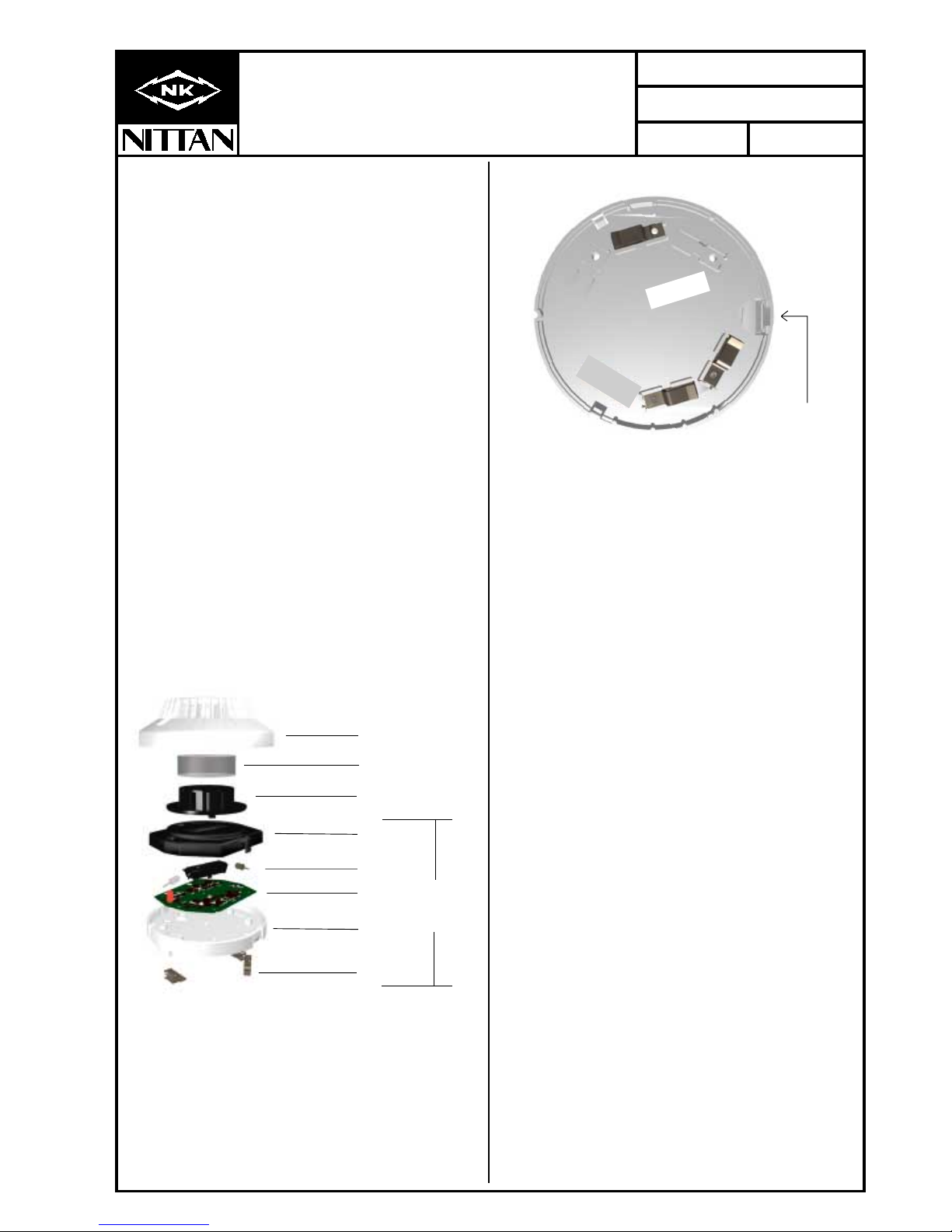
Cleaning
Figure 1:- 'Exploded' View of ST-P-AS sensor Assembly
i) Carefully remove the outer cover of the detector by
gently releasing the larger outer cover clip, (see figure 2
below), with a small screwdriver, this clip is visible from
the rear of the ST-P-AS sensor. It is not necessary to
use any excessive force.
Figure 2:- Rear view of ST-P-AS Sensor.
ii) Remove the chemically-etched insect screen.
iii) Remove the optic chamber by gently twisting in an
anticlockwise movement
DO NOT DISMANTLE ANY FURTHER
iv) Examine the optic chamber and the optic's bridge
and check for any dust or dirt which may give cause for
false alarm.
If the sensor is very dirty, damaged or corroded please
return the complete detector to Nittan for service.
v) If the parts of the sensor are still serviceable, proceed
to clean the outer shield case and plastic outer cover
using both a clean dry brush for dry dust and dirt. A lint-
free cloth moistened with alcohol may be used to remove
sticky deposits from the insect screen, optic chamber
and the optic's bridge.
vi) Reassemble the sensor in the reverse order. Refit
the plastic outer cover, aligning the LED indicator aper-
ture with the LED indicator. Check alignment of the outer
cover prior to fully pushing home in order to avoid distor-
tion of the insect screen.
Make sure that the three securing clips of the outer
cover are properly aligned and seated. 'Snap fit' the
plastic outer cover to the ST-P-AS body, taking care not
to compress the insect screen.
Ultrasonic Cleaning
This method may be used to good effect for the removal
of contamination from the outer cover, plastic optic
chamber, and chemically etched insect screen, only,
after they have been dismantled from the detector.
However, care must be taken in selection of the solvent
so as not to cause damage to the plastic and insect
Insect screen
Outer cover
Optic Support
PCB
Detector
body
Terminals
Shield Case
Optic chamber
Do not dissasemble
these parts as
this will void
warranty
Large outer
cover clip

02
NISM/STPA/02
DATE:
PAGE:
No:
ISSUE:
of57
ST-P-AS
ANALOGUE-ADDRESSABLE
PHOTOELECTRIC SMOKE SENSOR
INSTRUCTION MANUAL
MARCH 2001
screen. The solvent supplier should be consulted as to
it’s suitability.
Under no circumstances should the fully assembled
detector be cleaned without disassembly as this may
cause damage to the special treatment applied to
specific components within the detector.
Section 7 - SPECIFICATION
Model Reference: -ST-P-AS
Computer Reference: - 81100
Sensor Type: Photoelectric smoke
sensor
Operating Current: - 200
µ
amps
fire alarm (LED on)
3.2mA
Sensitivity: - BS5445/EN54 Part 7
Mass: - 114g (excluding base)
Charging Time: - 20 seconds
Ambient Temperature
Range: - -10 Deg.C. to
+50 Deg.C..
Section 8 - ENVIRONMENTAL
PARAMETERS
Temperature Considerations:
Over the range from -10 deg. C. to +50 deg. C..
Humidity:
Relative Humidity of up to 90%, measured at
50 deg. C., non condensing.
Section 9 - EMC
Installation
The installation shall be in accordance with the
regulations either of the approval body for an approved
system, or otherwise, to the national code of practice/
regulations for the installation of the fire alarm system,
e.g. BS 5839 part 1.
Electromagnetic Compatibility (EMC)
On a site where there is an unusually high level of
potential electrical interference, e.g. where heavy
currents are being switched or where high levels of R.F.
are prevalent, care then must be taken in the type and
routing of cables. Particular care should be given to the
separation of zone wiring from the cable carrying the
interference.
Please proceed to page 6.......................................

02
NISM/STPA/02
DATE:
PAGE:
No:
ISSUE:
of67
ST-P-AS
ANALOGUE-ADDRESSABLE
PHOTOELECTRIC SMOKE SENSOR
INSTRUCTION MANUAL
MARCH 2001
ST-P-AS
STOCK No. 81100
ANALOGUE PHOTOELECTRIC
SMOKE SENSOR
DISASSEMBLY WILL VOID WARRANTY
REMOVAL OF THIS LABEL IS PROHIBITED
Section 10 - ADDRESS SETTING:-
NITTAN DIL SWITCH SETTINGS FOR SENSORTEC MODEL TYPES: ST-I-AS, 5000/ION, 5000/OP AND
ST-H-AS, 5000/TEMP.
WARNING: Connect only to NITTAN (UK) LTD suitable and compatible analogue-addressable control panels.
If in doubt, check with control panel manufacturer.
DIL SWITCH SETTINGS - ALL SENSOR MODELS
Hold the sensor so that the product label can be correctly read. Set each digit on the appropriate eight switches
according to the address required.
64
8
16
32
4
1
= On
2
On
128
Rear of ST-P-AS Sensor and Address Switch Setting (DIL Switch)
Above switch setting set to
address 12 decimal.
=Off
Off
64
8
16
32
4
1
= On
2
On
128
Above switch setting set to
address 26 decimal.
=Off
Off
64
8
16
32
4
1
= On
2
On
128
Above switch setting set to
address 95 decimal
=Off
Off
64
8
16
32
4
1
= On
2
On
128
Above switch setting set to
address 126 decimal.
=Off
Off
64
8
16
32
4
1
2
On
128
OFF
CONNECTIONS/RATINGS
FUNCTION TERMINAL SPECIFICATIONS
SUPPLY/
SIGNAL
1
6
AUX
OUTPUT
3
+VE(ALSO AUX+VE)
-VE
-VE3mA MAX
USEWITH NITTANPROTOCOL NISM/WFM/02.
SETADDRESS PRIORTO USE.
AFFIX LABEL TO SEAL ADDRESS WINDOW
AMBIENT TEMP. -10 Deg. C. to +50 Deg.C.
SER. No. _________________________________
0004570
MADE IN UK
NITTAN (UK) LTD
02
NISM/STPA/02
DATE:
PAGE:
No:
ISSUE:
of77
ST-P-AS
ANALOGUE-ADDRESSABLE
PHOTOELECTRIC SMOKE SENSOR
INSTRUCTION MANUAL
MARCH 2001
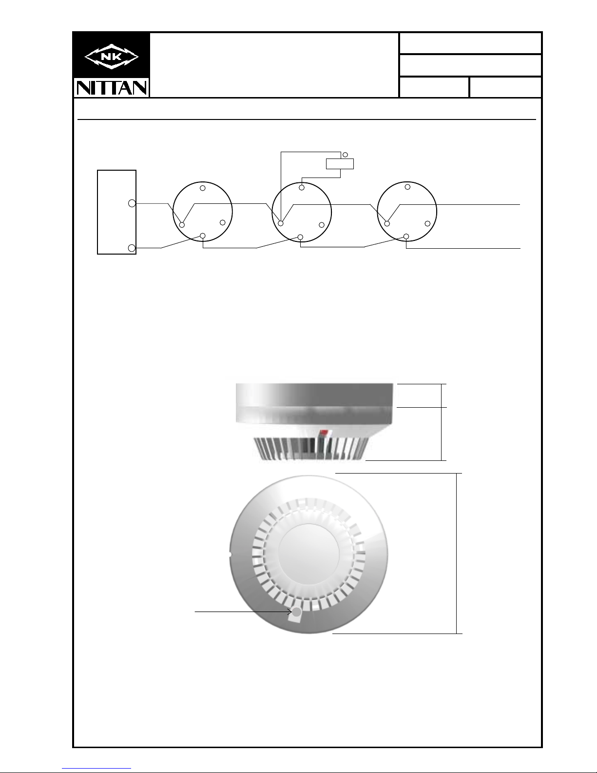
15mm
35mm
104mm
NOTE:
Clear LED: denotes
Photoelectric sensor.
Section 11 - CONNECTIONS (Also suitable for ST-I-AS and ST-H-AS sensors)
Section 12 - DIMENSIONS
STB-4 base
_
6
5
33
6
5
6
3
5
1 1
STB-4 base
LED
1
+
STB-4 base
+
SIG+
S-
Low current LED 3mA max.
(STA-R1).
loop return to
control panel

Document No. NISM/STPI/02
Date MARCH 2001
comes SENSORTEC.........
From world leaders in SENSOR TECHNOLOGY
NITTAN (UK) LTD.
Hipley Street,
Old Woking,
Surrey, England,
GU22 9LQ United Kingdom
Tel: +44 (0) 1483 769555
Fax: +44 (0) 1483 756686
Web Site: www.nittan.co.uk
e-mail: [email protected]
Quality System Certificate No. 041
Assessed to BS EN ISO 9002
ST-P-AS
ANALOGUE ADDRESSABLE
PHOTOELECTRIC SMOKE SENSOR
INSTRUCTION MANUAL
LPCB REF: 041c/09
Other Nittan Smoke Alarm manuals

Nittan
Nittan EVC-P User manual

Nittan
Nittan EVA-PYH User manual

Nittan
Nittan ST-P-OM User manual

Nittan
Nittan Evolution EVC-DP User manual

Nittan
Nittan EVA-PYH User manual

Nittan
Nittan CKLD-KPT2 User manual

Nittan
Nittan evolution EVC-P User manual

Nittan
Nittan EVCA-P User manual

Nittan
Nittan EVC-PY-IS User manual

Nittan
Nittan Evolution-Advanced EV-DP User manual


