Nittan ST-P-OM User manual


INSTRUCTION MANUAL
ST-P-OM
Photoelectric Smoke Detector
NISM –ST-P-OM
PAGE: 2 of 8
ISSUE No: 2
DATE: 03/10/11
NISM-ST-P-OM-INST MANUAL-001 ISS 2 03/10/11 2/8
INTRODUCTION
The ST-P-OM Photoelectric Smoke Detector is an updated version of the ST-
P sensortec photoelectric smoke detector
The ST-P-OM is an elegantly designed, low profile detector which is
aesthetically pleasing, thus enabling it to blend unobtrusively into
modern working environments.
The ST-P-OM is compatible with other existing conventional fire detection
systems.
www.acornfiresecurity.com
www.acornfiresecurity.com

INSTRUCTION MANUAL
ST-P-OM
Photoelectric Smoke Detector
NISM –ST-P-OM
PAGE: 3 of 8
ISSUE No: 2
DATE: 03/10/11
NISM-ST-P-OM-INST MANUAL-001 ISS 2 03/10/11 3/8
ST-P-OM
CONTENTS:-
Section 1 - Introduction - Page 3
Section 2 - Operation - Page 3
Section 3 - Detector Models - Page 4
Section 4 - Base Models - Page 4
Section 5 - Installation - Page 4
Section 6 - Maintenance &
Cleaning - Page 5
Section 7 - Specification - Page 6
Section 8 - Environmental
Parameters:- - Page 6
- Temperature - Page 6
- Humidity - Page 6
Section 9 - EMC - Page 6
Section 10 - Connections - Page 7
Section 11 - Dimensions - Page 7
Section 1 - INTRODUCTION
The ST-P-OM is an attractively-styled, low profile
photoelectric smoke detector for use in conventional
fire detection systems.
The ST-P-OM has a chemically etched, stainless
steel insect screen therefore reducing the ingress
of insects and airborne contaminants.
ST-P-OM features:
* Optical detector, detecting visible particles
of combustion
* Low profile, stylish appearance
* Supplied with protective dust cover, (remove
during commissioning)
* Non-polarised terminals
* Unauthorised head removal signal facility
* Low monitoring current
* OMNIVIEW
TM
360oLED fire alarm indicator
* Remote indicator output
* Compatible with UB-4, UB-4SD and STB-4SE
bases
Section 2 - ST-P-OM OPERATION
The smoke chamber of the ST-P-OM is constructed
so that light cannot enter from outside, but smoke can
pass through the chamber slots. The ST-P-OM
utilises the light scatter sensing principle. The LED
pulses every 8 seconds to maintain a low monitoring
current. A quick charge time (20 seconds) is also
achieved. The detector incorporates an alarm
verification function which requires two successive
pulses before an alarm is given.
The interval between the first and second pulse is
automatically reduced to four seconds after the first
alarm level is monitored. The detector design provides
strong immunity to air velocities, contamination and RF
interference.
The geometry of the smoke chamber and optics
support assembly is designed to give the best possible
signal to noise ratio, resulting in excellent response
characteristics.
www.acornfiresecurity.com
www.acornfiresecurity.com

INSTRUCTION MANUAL
ST-P-OM
Photoelectric Smoke Detector
NISM –ST-P-OM
PAGE: 4 of 8
ISSUE No: 2
DATE: 03/10/11
NISM-ST-P-OM-INST MANUAL-001 ISS 2 03/10/11 4/8
Section 3 - DETECTOR MODELS
The ST-P-OM photoelectric smoke detector is
supplied, as standard, with four terminals.
The ST-P-OM has the facility to activate a remote
LED indicator or auxiliary function, as standard.
The terminals on the ST-P-OM detector
head are configuredasfollows:-
Terminal 3 = Zone positive in/out.
Terminal 1 = Zone negative in.
Terminal 6 = Zone negative out.
Terminal 5 = 20 mA @ 24V d.c. switched output.
Section 4 - BASE MODELS
A variety of bases are available for use with the
ST-P-OM detector. It is important to use the correct
base for each application. The standard range
available is as follows:-
i) UB-4base: having 4 terminals, for standard
use with ST-P-OM detector including the
auxiliary output function.
ii) UB-4R base: having 4 terminals, andlimiting
resistorfor standard usewith ST-P-OM detector
including the auxiliary output function.
iii) UB-4SD base: This is identical to the standard
UB-4 base, but also includes a schottky
diode for head removal fault monitoring.
The schottky diode is used in some fire
systems to ensure power is maintained, in
the event of an unauthorised detector head
removal, to other detectors further on the
zone.
iv) STB-4SE base: Similar to UB-4 base, except
deeper
v) STB-4SE-24VR base: Relay contact base.
Section 5 - INSTALLATION
In normal use, the ST-P-OM detector will be installed
at ceiling level. Pass the field wiring through the cable
hole in the centre and from the rear of the base.
Offer up and affix the base to the ceiling or conduit
fitting with screws via the base mounting holes.
Connect the field wiring to the base terminals, as
detailed on page 6 making sure the wiring does not
obstruct fitting of the detector head. Fit the detector
head by inserting it into the base and turning
clockwise until the notch in the detector rim aligns with
base locking screw. The OMNIVIEW
TM
360
o
indicator
permits visibility from any angle.
Fit the plastic dust cover supplied over the detector
to keep out dust etc, until the system is
commissioned. If the dust cover is not fitted and the
environment is slightly dusty, such as when building
work is being completed, for example, problems of
false alarms are likely to occur after commissioning
unless cleaning of the detector is undertaken. At
commissioning, the dust cover should be removed
and discarded.
NOTE: THE PLASTIC DUST COVER MUST BE
RE- MOVED FROM THE DETECTOR IN ORDER
FOR THE DETECTOR TO FUNCTION
CORRECTLY.
www.acornfiresecurity.com
www.acornfiresecurity.com

INSTRUCTION MANUAL
ST-P-OM
Photoelectric Smoke Detector
NISM –ST-P-OM
PAGE: 5 of 8
ISSUE No: 2
DATE: 03/10/11
NISM-ST-P-OM-INST MANUAL-001 ISS 2 03/10/11 5/8
Section 6 - MAINTENANCE AND
CLEANING
Maintenance:
The ST-P-OM detector is a high quality product
engineered for reliability. In order to obtain optimum
performance, periodic maintenance is required. If
proper preventative maintenance is not carried out,
there is a likelihood of malfunction, as a dirty detector
is more likely to cause a false alarm.
Servicing:
Servicing of the system should be carried out in
accordance with the requirements of BS 5839 Part 1,
Fire Detection and Alarm Systems for Buildings:
Code of Practice for System Design, Installation and
Servicing.
The maintenance procedures described below
should be conductedwiththefollowingfrequency:
One month after installation: Routine Inspection,
and every 3 months
thereafter.
Every 6 months: OperationalTest
Every 12 months: Functional Test
and Cleaning.
All above frequencies of maintenance are dependent on
ambient conditions.
Routine Inspection:
i) Ensure the detector head is secure and
undamaged.
ii) Check the smoke entry apertures are in no way
obstructed.
iii) Ensure the surface of the detector’s outer cover
is clean. If there are deposits due to the presence
of oil vapour, dust etc, then the detector should be
cleaned in accordance with the cleaning instructions
detailed later in this manual. It may be advisable to
ensure that such cleaning is conducted regularly in
the future.
iv) Ensure no equipment which may generate
combustion products or fine airborne particles, has
been installed in the vicinity of the detector since the
last routine inspection. If such equipment has been
installed, then you should notify the Fire Safety
Officer or other competent authority that its
presence may cause false alarms.
OperationalTest:
The purpose of the Operational Test is to confirm
the detector’s correct operation in response to a
smoke condition.
i) Take any necessary precautions at the control
panel to limit the sounding of the alarm
sounders/bells and any fire service summoning
device.
ii) Introduce a discrete amount of smoke into the
detector head, e.g. using a 'No Climb -Solo' smoke
test head. Check that the detector gives an alarm
condition within 15 seconds. Check the LED indicator
on the ST-P-OM detector illuminates and any remote
indicator LED fitted also illuminates.
iii) After the detector has given the alarm
condition, reset the detector from the control
panel. It may be necessary to allow a short time
to elapse before resetting the detector, to allow
any residual smoke from the test to disperse.
iv) Before proceeding to the next detector, ensure
that the detector just tested does not re-operate due
to the presence of residual smoke.
FunctionalTest:
The detector may be returned to Nittan (UK) Ltd
for functional testing.
Cleaning:
Note: The detector head should NOT
be disassembled.
i) Carefully remove the detector head from its base.
ii) Use a soft, lint-free cloth, moistened with alcohol
for sticky deposits, to clean the plastic casing.
iii) Using a soft bristle brush (e.g. an artist's
paint- brush) carefully brush between the vanes in
a linear motion away from the smoke entry
apertures.
iv) It is permissible to blow dust from the chamber,
without removing the cover, using a clean air line.
v) If the unit needs further cleaning, or is damaged
or corroded, please return the complete detector to
Nittan (UK) Ltd. for service.
www.acornfiresecurity.com
www.acornfiresecurity.com

INSTRUCTION MANUAL
ST-P-OM
Photoelectric Smoke Detector
NISM –ST-P-OM
PAGE: 6 of 8
ISSUE No: 2
DATE: 03/10/11
NISM-ST-P-OM-INST MANUAL-001 ISS 2 03/10/11 6/8
Section 7 - SPECIFICATIONS
ModelReference: - ST-P-OM
ComputerReference: - F02C82220
DetectorType: - Photoelectric
smoke detector
Sensitivity - 3% Obscuration
per metre
Supply Voltage: - 24V dc nominal
(range 12V to 30V)
Voltage Ripple: - 20% maximum
Alarm Characteristics: - 6V d.c. between
+(terminal 3) and
- (terminals 1,6)
at 25 deg. C
Monitoring Current: - 40
m
A max. at 24V d.c.
Alarm Current: - Must be externally
limited to 65mA. Max
Charging Time: - 20 seconds
Ambient Temperature
Range: - -10
o
C to +55
o
C
Standard: - EN54-7: 2000
EMCConformance: - BSEN50130-4:1996
(Immunity)
BSEN61000-6-3:2001
(Emissions)
Mass: - 118g(excluding
base)
IPRating: - IP40
Section 8 - ENVIRONMENTAL
PARAMETERS
TemperatureConsiderations:
Over the range from -10
o
C to +55
o
C.
Humidity:
Relative Humidity of up to 95%, measured at 50
o
C,
non condensing.
Section 9 - EMC
Installation
The installation shall be in accordance with the
regulations either of the approval body for an approved
system, or otherwise, to the national code of practice/
regulations for the installation of the fire alarm system,
e.g. BS 5839 part 1.
ElectromagneticCompatibility(EMC)
In a site where there is an unusually high level of
potential electrical interference, e.g. where heavy
currents are being switched or where high levels of
R.F. are prevalent, care then must be taken in the
type and routing of cables. Particular care should be
given to the separation of zone wiring from the cable
carrying the interference.
www.acornfiresecurity.com
www.acornfiresecurity.com
INSTRUCTION MANUAL
ST-P-OM
Photoelectric Smoke Detector
NISM –ST-P-OM
PAGE: 7 of 8
ISSUE No: 2
DATE: 03/10/11
NISM-ST-P-OM-INST MANUAL-001 ISS 2 03/10/11 7/8
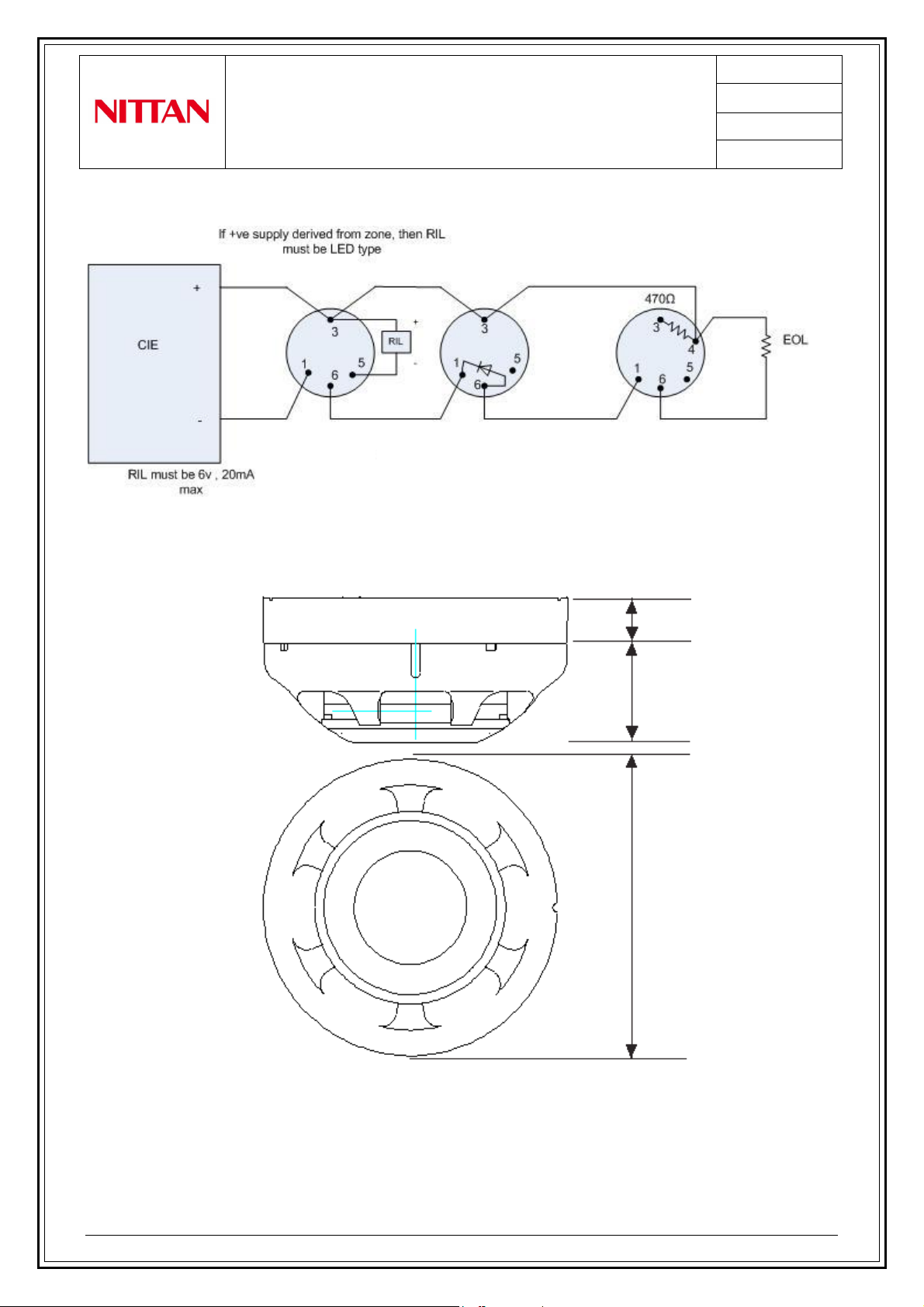
Section 10 –CONNECTIONS
Section 11 –DIMENSIONS
15mm
33mm
Æ
104mm
UB-4 Base
STB
-
4SE Base
UB
-
4SD Base
UB
-
4
R
Base
www.acornfiresecurity.com
www.acornfiresecurity.com

INSTRUCTION MANUAL
ST-P-OM
Photoelectric Smoke Detector
NISM –ST-P-OM
PAGE: 8 of 8
ISSUE No: 2
DATE: 03/10/11
NISM-ST-P-OM-INST MANUAL-001 ISS 2 03/10/11 8/8
Section 11 –DISPOSAL
This symbol on the ST-P-OM indicates that this product must not be disposed of with your other
household waste. Instead, it is your responsibility to dispose of your waste equipment
by handing it over to a designated collection point for the recycling of waste electrical
and electronic equipment. The separate collection and recycling of your waste
equipment at the time of disposal will help to conserve natural resources and ensure
that it is recycled in a manner that protects human health and the environment. For
more information about where you can drop off your waste equipment for recycling,
please contact your local city office or your household waste disposal service.
www.acornfiresecurity.com
www.acornfiresecurity.com
Table of contents
Other Nittan Smoke Alarm manuals

Nittan
Nittan EVA-PYH User manual

Nittan
Nittan evolution EVC-P User manual

Nittan
Nittan ST-P-AS User manual

Nittan
Nittan Evolution EVC-DP User manual

Nittan
Nittan EVC-PY-IS User manual

Nittan
Nittan EVC-P User manual

Nittan
Nittan EVA-PYH User manual

Nittan
Nittan CKLD-KPT2 User manual

Nittan
Nittan Evolution-Advanced EV-DP User manual

Nittan
Nittan EVCA-P User manual


