Nitto Kohki BC-005 User manual

Due to continuous product development/improvement the specifications and
configurations in this document are subject to change without prior notice.
Specifications
Model BC-005
Maximum Operating Pressure MPa 0.6
Air Consumption (No Load) m3/min 0.22
Maximum Power W 72
Rated Speed (Maximum Free Speed) min-1 420
Mass (Weight) Kg 0.75
Sound Pressure Level dB(A) 88.8
Sound Power Level dB(A) 99.8
Vibration Level [Uncertainty K]
(according to ISO20643)
m/s2 [m/s2]
4.2 [0.91]
Thread Size of Air Inlet Rc1/8
Manufactured by :
NITTO KOHKI Co., Ltd.
2-9-4, Nakaikegami, Ohta-ku,
Tokyo, 146-8555, Japan
TEL : (81)-3-3755-1111
FAX : (81)-3-3753-8791
URL : www.nitto-kohki.co.jp
Keep the manual handy – so you can use it whenever necessary.
Orijinal Instructions
PNEUMATIC DEBURRING TOOL
Please read this manual carefully before you attempt to use
your tool so that you may use it properly and safely.
BURR CUTTER Model BC-005
PROFESSIONAL TOOL

1
Thank you very much for your purchase of this
Nitto Kohki products.
Before using your tool, please read this manual
carefully so that you may use it properly to get
the most out of it.
Please keep the manual handy - so you can
use it whenever necessary.
・English : Please ask your dealer or
distributor for instruction manual
in local language(s).
・German : Bitte fragen Sie lhren Händler
nach eine Betriebsanleitung in
Landessprache.
・French : S'il vous plait, veuillez demandez
á votre foumisseur de manuel
instruction en langue locale.
・Spanish : Por favor, cantacte con su
distribuidor para el manual de
instrucciones en español.
・Portuguese : Por favor pessa ao seo agente
ou distribuidor o manual de
instrucces ih linguagen local.
・Italian : Per Manuale lstruzioni in lingua
locale Vi preghiamo di rivolgervi
al rivenditore o distributore.
・Dutch : Vraag uw handelaar
om een nederladstalige
gebruiksaanwijzing.
・Swedish : Be er lokala Åtreförsäljare eller
distributör om manualer pá
svenska.
・Danish : Venligst henvend Dem til
den danske distributør for
instructions manualer.
・Polish : Prosze pytac swojego dealera
lub dystrybutora o instrukcje
obslugi w jezyku localnym.
・中文 :
CONTENTS page
IMPORTANT SAFETY INSTRUCTIONS …………………… 2
GENERAL: TOOLS …………………………………………… 2
GENERAL: PNEUMATIC TOOLS ………………………… 3
INSTRUCTIONS FOR THIS TOOL ………………………… 4
1. USAGE …………………………………………………… 4
2. CHECK THE CONTENTS OF THE PACKAGE ……… 4
3. NAME OF PARTS ……………………………………… 4
4. AIR SUPPLY ……………………………………………… 5
5. HOW TO OPERATE THE TOOL ……………………… 5
6. STORAGE ………………………………………………… 7
7. ORDERING SERVICE PARTS ………………………… 7
8. THREAD SIZE OF HOSE FITTING …………………… 7
9. EXPLODED DIAGRAM : BC-005 ……………………… 8
PICTOGRAM
Warning:Itmightbedangeroustooperatethetool
iftheinstructionssuppliedarenotfollowed.
Usingthistoolimproperlycouldresultinserious
injury.Readtheinstructionmanualbeforeusing.
Alwayswearsuitableeyeprotection.
Alwayswearsuitablehearingprotection.
Alwayswearrespiratoryprotectiveequipment
(PPE).
The following Safety notations are used throughout the manual to highlight safety precautions for the user and for the tool.
WARNING: Indicates a potentially hazardous situation which, if not avoided by following the
instructions given, could result in death or serious injury.
CAUTION: Indicates a potentially hazardous situation which, if not avoided by following the
instructions given, could result in injury or material damage.
Please note, however, that failure to observe safety precautions under the “ Caution” category could result in a serious
occurrence depending on the situation: please observe all safety precautions in the manual.
Caution: Important precautions for tool setup, operation and maintenance.

2
IMPORTANT SAFETY
INSTRUCTIONS
When using the tool, please observe the safety
precautions below to prevent possible accident or
injury.
GENERAL: TOOLS
WARNING
TO OPERATORS
●Wear proper clothing for the type of work being
done.
Take care so that clothing, ties, hair, etc. will not
become entangled with the moving parts. If items
become entangled, it will cause the operator to be
pulled towards the tool and lead to possible cause of
accident or injury.
●Always wear suitable eye protection.
Vision correction glasses are not safety glasses.
Always wear appropriate safety glasses when doing
your job.
●Always wear suitable hearing protection.
●Wear respiratory protective equipment (PPE).
Wear respiratory protective equipment (PPE) when
working in an environment where dust particles are
generated in operation.
●Avoid working posture that is too stressful.
Always ensure a firm footing and well balanced
posture.
●Do not operate the tool if you are too tired.
●Never touch any moving parts of the tool when
running.
ABOUT WORK AREA
●Keep the work area clean.
Cluttered work areas (e.g. workbench) invite
accidents.
●Carefully select the work area.
Do not expose the tool to rain.
Do not use the tool in a wet or soaked area.
See that the work area is adequately illuminated.
●Never work near inflammable liquid or in a
potentially explosive atmosphere.
●Keep children away from the work area.
Keep children and unauthorized people away from
the work area to avoid accident or injury.
●Some tools generate high noise levels.
Check to be sure that the use of this tool conforms
to all local noise regulations.
BEFORE OPERATION
●Inspect tool before use.
Before using, check that screws are securely
tightened, that any protective cover or guard is
securely in place, other parts are free from damage
and that the tool runs as it should.
Check that moving parts are properly adjusted for
positioning and tightened, that parts are free from
damage and properly mounted, and that all other
parts are in good condition for normal operation.
Should you find any damage to the protective
cover or other part, replace it in accordance with
the Operation Manual. If there are no instructions
in the Manual, please contact the sales agent
through which you have purchased your tool or an
authorized dealer near you for repair.
Likewise, if a switch failure occurs, contact sales
agent through which you have purchased your tool
or an authorized dealer near you for repair. .
Do not use the tool if it does not start or stop with
the start/stop switch.
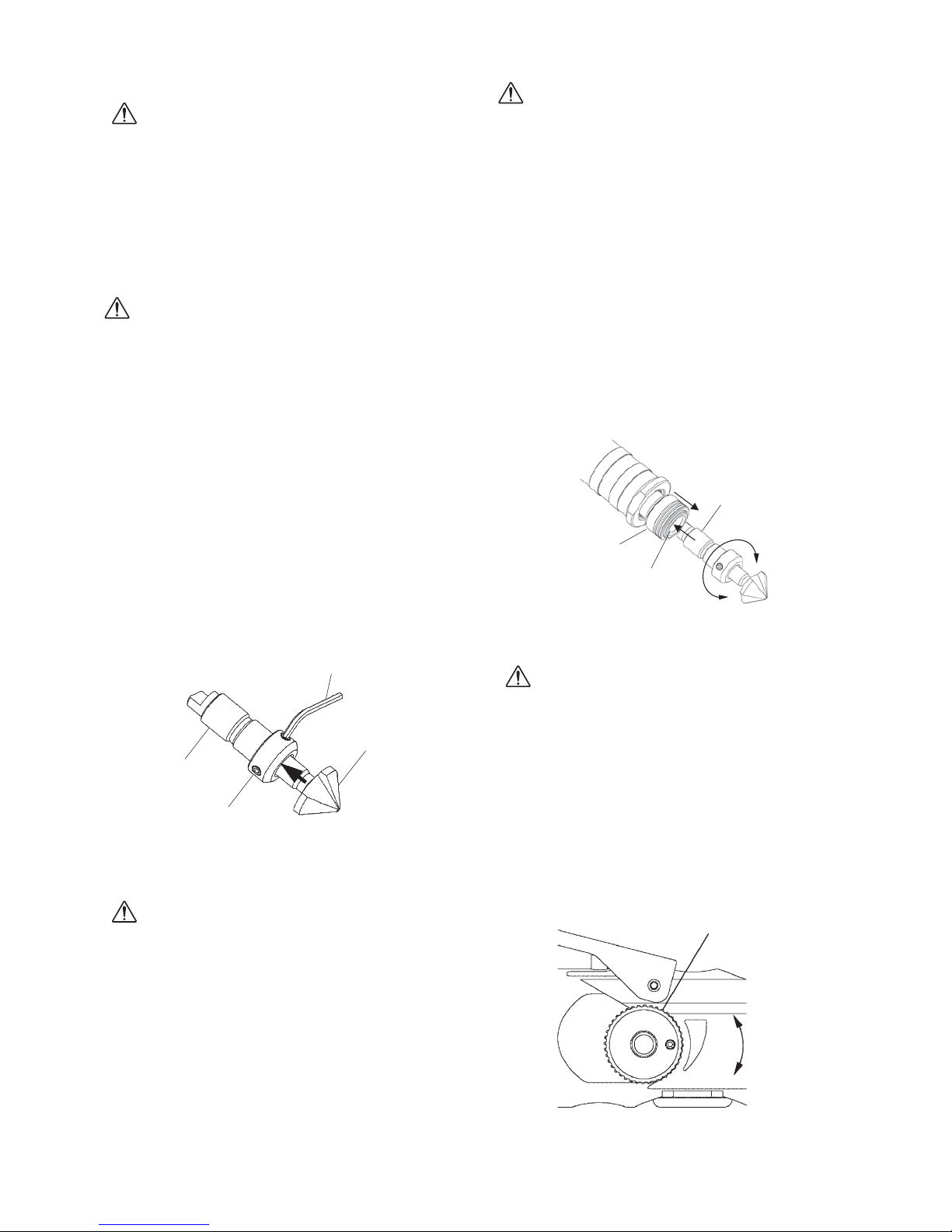
●Securely mount cutter
An improperly mounted cutter may fly out, causing
possible damage to the tool or injury to the operator.
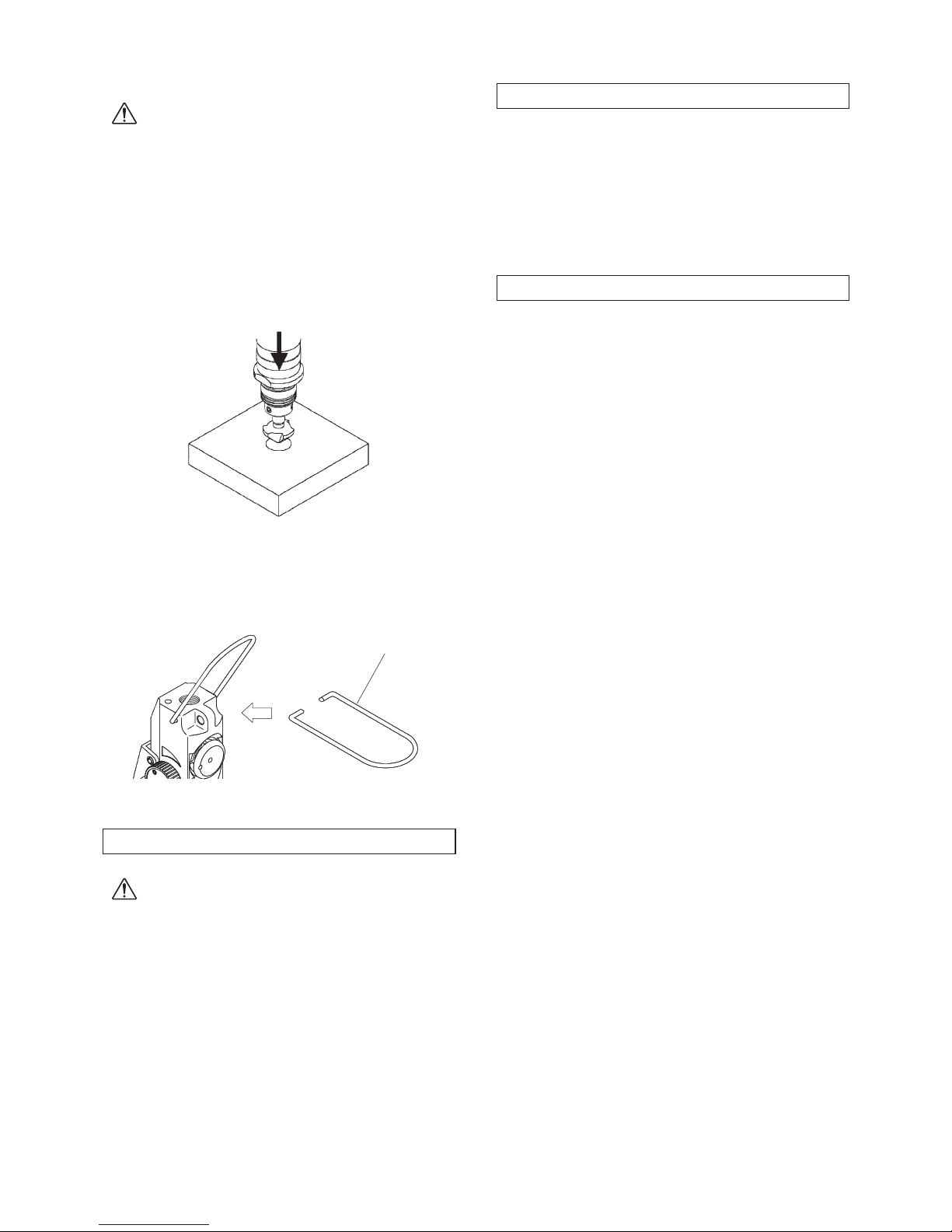
●Always remove spanner, wrench, etc., once
adjustment has been made with them.
●Use a tool appropriate for the application.
Avoid heavy-duty application that is beyond the
capacity of the tool.
●Do not use the tool for purposes other than what
it is designed for.
●Do not abuse tool.
Use tool in accordance with the specifications: youʼll
get the most out of it while ensuring safety.
●Securely fasten workpiece in place.
Use a vice or clamp to securely fasten the workpiece in
place. It is much safer this way than holding it in your
hand, allowing you to operate the tool with both hands.
ABOUT HANDLING
●How to store tool.
When the tool is not used, store it in a dry area and
out of reach of children.
●How to carry tool.
Do not touch the start switch while the tool is being
carried.
●Do not leave the tool unattended while it is
running.
Turn off the start switch and disconnect the tool from
power source. Do not leave the work area until the
tool comes to a complete stop.

3
MAINTENANCE/SERVICE
●Do not take apart or modify tool.
Disassembly or modification carried out without
the supervision of a qualified or authorized service
engineer could result in an accident or injury.
●Inspect cutting tool and accessories, etc.
Always check to see that cutting tool and
accessories, etc. are in good operating condition
without damage or deterioration before you mount
them on the tool. Should you find any damage to
an accessory or part, please contact sales agent
through which you have purchased your tool or an
authorized dealer near you for repair.
●Check parts for damage.
When you have found damage to accessory or other
part, carefully check the damaged part to determine
the extent of influence it has upon the functions
of the tool – that is, determine whether it can still
perform its normal functions.
Check to see that the linkage of the moving parts
is OK, that all parts are OK without damage,
that they are properly mounted, and that the tool
functions normally. Should you find any damage
to an accessory or part that may hamper proper
functioning of the tool, please contact sales agent
through which you have purchased your tool or an
authorized dealer near you for repair.
●Have your tool repaired at an authorized Nitto
Service Center.
For repair or parts replacement, please contact the
sales agent through which you have purchased your
tool or an authorized dealer near you.
●Use only Nitto genuine parts.
Use of improper parts may result in serious
occurrence.
To obtain a Nitto genuine part, consult this Manual
or contact the sales agent from which you have
purchased your tool directly.
●Do not detach label or nameplate from tool.
When a label/nameplate gets damaged, worn or
becomes missing, contact the sales agent through
which you have purchased your tool or Nitto Kohki
Co. Ltd, directly for a replacement.
DISPOSAL
●When a tool is taken permanently out of service, it is
advised that the tool is disassembled, degreased and
parts separated by material and recycled locally in
the appropriate manner.
GENERAL: PNEUMATIC
TOOLS
WARNING
●Use appropriate air pressure.
Excessively high air pressure will increase the
number of revolutions or strokes causing not only
potential premature failure/breakage but could also
lead to an unexpected accident or injury.
●Connect tool to air supply line.
There are various types of pipes running in a factory
in addition to the pneumatic line (such as oxygen,
nitrogen, gas and water). For this reason, always
ensure that you are connecting to the pneumatic line.
●Start tool properly.
Turn the start switch OFF before connecting to the
air supply line.
●Always disconnect the tool from the air supply
line before putting on/taking off any accessory
and prior to carrying out any maintenance work.
●Avoid exposure to exhaust air.
Pneumatic tool exhaust air contains oil and
contaminated moisture. Make sure the exhaust air is
not directed towards your face or anyone else within
the work area.
●Keep tool off electricity.
This pneumatic tool is not electrically insulated. To
avoid a potential electric shock do not use where
there is a possibility of coming into contact with live
electricity.
CAUTION
●Handle tool carefully.
Abusive use of tool could invite failure or accident.
Do not throw, drop or shock the tool.
●Handle connecting hose carefully.
Do not carry the tool by the air hose.
Do not pull the air hose to disconnect.

4
3 NAME OF PARTS
Lock Lever
Dial
Duster Nozzle
Duster Button
Throttle Lever
Chuck
Sleeve
INSTRUCTIONS FOR THIS
TOOL
About Your Tool
WARNING
●Protect your body from the chips/filings.
Hot chips/filings may fly out from the work piece.
Always wear safety glasses, dust mask, earplugs,
gloves (except knitted gloves) and long-sleeved
garment.
Keep your face well away from the work piece.
●This tool is a push start type.
Before starting operation, turn on the throttle lever
to start the motor, and press the countersink against
the workpiece to be machined.
●There are three types of available shank
diameters. Do not use a countersink that does
not fit any of the shank diameters.
●To ensure high-quality operation and safety, do
not use a worn or damaged countersink.
●When the connection hose is disconnected from
the tool, exercise care not to allow cutting chips
and foreign substances to enter the tool through
the air inlet port of the tool.
1 USAGE
This tool is designed for deburring workpiece with
countersink.
2 CHECK THE CONTENTS OF THE PACKAGE
Check the contents and make sure that the tool does
not have any damage which may have occurred
during transportation. The contents should correspond
to the list as follows. In case of damage/missing
parts, please contact the sales agent from whom you
purchased the tool.
Package Contents Qty check
BURR CUTTER BC-005 1set
Chuck 10mm 1
Chuck 8mm 1
Chuck 6mm 1
Hex. Socket Screw Key 2.5 1
Hook 1
Bushing R1/8×NPT1/4 1
Instruction Manual 1
Declaration of Conformity 1
Fig.1

5
4 AIR SUPPLY
CAUTION
●Draw off drainage before starting operation. If
the drainage enters into the tool, it can freeze
around the exhaust port of the tool and result in
output power reduction.
4-1. Air Pressure
Adjust air pressure to 0.6MPa (or 6 kgf/cm2) with
the air regulator. Lower pressure may result in
insufficient performance. Higher pressure may result
in premature wornout of parts. It is important to
maintain the proper pressure with pressure regulator
on air line.
4-2. Air Line (Fig.2)
Use a 9.5 mm (3/8”) I.D. air hose between the
compressor and the tool. Compressed air comes
to be cooled down and its drain be separated, as
soon as the air leaves the compressor. The drain,
however, is condensed in the piping, and can
enter into the tool mechanism, and may cause
malfunction.
So, install an air filter and an oiler between the
compressor and the tool.
4-3. oiler
Install an oiler between the compressor and the tool.
Use machine oil ISO VG-10 for lubrication and rust
prevention. Negligence of the oil supply may cause
damages on the tool. Lubricating the tool with high
viscosity oil reduces the tool performance.
4-4. Lubrication (Fig.2)
Before starting the tool, disconnect air hose from
the tool and supply a few drops of machine oil ISO
VG-10 to the air inlet port of the tool. Then reconnect
and make idle running for a few seconds so that the
oil should reach every part in the tool.
AirRegulator Oiler
AirFilter
Compressor
Cupla
Tool
Lubrication
9.5mm (3/8in) I.D.
Hose
Fig.2
5 HOW TO OPERATE THE TOOL
WARNING
●Always wear safety glasses during operating the
tool. Wear respiratory protection when working
in an environment where dust particles are
generated during operation.
●Make sure the Throttle Lever is in the OFF position
before connecting the air supply hose to the tool.
●Always disconnect the air supply hose from the tool
before putting on/taking off countersink or replacing
parts.
●Never touch any moving parts of the tool when
running.
5-1. Dimensions of attachable countersink
The countersink that can be fitted into the chuck
supplied with the tool comes in three shank
diameters (Fig.3).(Table 1)
Fig.3
Table 1 Fitting table
Parts No. d(φmm)
Chuck 10mm 10
Chuck 8mm 8
Chuck 6mm 6
※Use a countersink for the goods on the market.
5-2. Start and Stop (Fig.4)
CAUTION
●This tool is a push start type.
(1) Check that a Throttle Lever is turned off and
connecting the tool to the hose leading to air
supply line.
(2) Hold the tool, ①tilt the Lock Lever, and ②grasp
the Throttle Lever to start.
※The countersink does not rotate in this state.
(3) ③When the Throttle Lever is released, it will
automatically turn off.
Fig.4
Lock Lever①Tilt
②ON
③OFF Throttle Lever

6
CAUTION
●Exercise care not to allow cutting chips to
enter the holder into which the chuck will be
inserted. If there are cutting chips in the holder,
thoroughly remove the cutting chips, and then
mount the chuck.
(1) Insert the chuck into the chuck holder of the tool.
(2) The chuck can be inserted all the way into the
holder by turning and pushing it in with the sleeve
kept down. (Fig.6)
(3) The chuck will not be locked as long as the sleeve
is kept down.
※Release the hold on the sleeve. It will return to
the original state, and the chuck will be locked.
(3) To remove the chuck, pull it out with the sleeve
kept down.
Chuck
Chuck Holder
Sleeve
Fig.6
5-5. Adjusting the Rotation Speed
WARNING
●Never touch any moving parts of the tool when
running.
When the dial is turned, the amount of airflow is
changed to adjust the rotation speed.
When the dial is turned to the furthest counterclockwise
position, the tool reaches the maximum rotation
speed. Adjust the rotation speed according to the
chamfering work. (Fig.7)
※The motor does not start to run when the dial is
throttled.
High
Dial
Low
Fig.7
5-3. Attaching and detaching the Countersink
WARNING
●Always disconnect the air supply hose from the
tool before adjusting the countersink.
●Do not fail to wear gloves when replacing the
countersink.
●Allow the countersink adequate time to cool
off after use as countersink can reach extreme
temperatures.
CAUTION
●Use a chuck matching the shank diameter.
●Exercise care not to allow cutting chips to enter
the holder into which the countersink will be
inserted. If there are cutting chips in the holder,
thoroughly remove the cutting chips, and then
mount the chuck.
(1) Using the Allen key wrench supplied with the tool,
loosen the three hexagon socket head screws
of the chuck matching the shank diameter of the
countersink used.
(2) Insert the shank of the countersink all the way into
the chuck, and securely tighten the three hexagon
socket head screws. (Fig.5)
(3) To detach the countersink, loosen the three
hexagon socket head screws.
Fig.5
Chuck
Countersink
Hex. Socket Screw Key 2.5
Hex. Socket Set Screw
5-4. Attaching and detaching the Chuck
WARNING
●Always disconnect the air supply hose from the
tool before adjusting the chuck.
●Do not fail to wear gloves when replacing the
chuck.
●Allow the countersink adequate time to cool off
after use as indexable inserts can reach extreme
temperatures.

7
5-6. How to use
CAUTION
●This tool is a push start type.
If the throttle lever is turned on with the countersink
pressed against the workpiece or the countersink is
suddenly pressed against the workpiece, it will lead
to be broken.
With the workpiece fixed and the throttle lever turned
on, insert the countersink into the hole in the worpiece,
and slowly press it against the workpiece. (Fig.8)
Fig.8
5-7. Hanging the hook
Use a hook for hanging the tool.(Fig.9)
Hook
Fig.9
6 STORAGE
WARNING
●When tool is not used, store it out of reach of
children.
Avoid storing the tool in a location subject to high
humidity. If the tool is left as it is used, residual
moisture on the inside can cause rusting. Before
storing, and after operation, oil the tool at the air inlet
with machine oil ISO VG-10 and run it for a short time.
7 ORDERING SERVICE PARTS
●For further operational and handling information or
for replacement of parts and components, contact
the company from whom you purchased the tool or
an authorized dealer.
●In ordering parts and components give each part
number, part name and quantity required.
●Use only NITTO genuine parts.
8 THREAD SIZE OF HOSE FITTING
The product comes has air supply inlet of Rc(metric)
thread. Connect the Bushing R thread×NPT thread
included as standard accessories, if you would like to
have American NPT thread instead.

8
9 EXPLODED DIAGRAM : BC-005
WARNING
This diagram is for your reference only. Do not attempt to service or repair the Tool. Do not take the Tool apart.
Contact an authorized Nitto dealer for all service and repair of the Tool. Improper service and repair can cause
accidents and service injuries. Never attempt to modify the Tool. Never attempt service or repair the Tool yourself.
No. PartsNo. Parts Name Qty
1 FQ00129 External Retaining Ring WR-20 1
2 TQ13910 Spring 0.7x20.9x21 1
3 TQ13909 Sleeve 1
4 TQ06710 External Retaining Ring ISTW-20 1
5 TQ05260 Oil Seal G20x26x4 1
6 TQ13894 Needle Bearing HK2016 1
7 TB09383 Housing Sub Ass'y 1set
8 (TQ14024) Label Caution 1
9 TB09389 Clutch B Assʼy 1set
10 TP00518 Ball 1/8 3
11 TQ02096 Parallel Pin 5x16 1
12 TQ13907 Spring 0.5x4.1x15.5 1
13 TQ13904 Clutch A 1
14 TQ13903 Ball Bearing 6001LLU 1
15 TB09387 Spindle Sub Assʼy 1set
16 TQ06893 Parallel Key Both Ends Round 3X3X6 1
17 TB09385 Carrier Assʼy 1set
18 TB09384 Planetary Gear 15 Assʼy 3set
19 TQ13906 Ring Gear 1
20 TQ13905 Lock Plate 1
21 TQ13888 Rubber Sheet 1
22 TQ07225 Ball Bearing 695ZZ 1
23 TQ13345 End Plate B 1
24 TQ13889 Rotor 1
25 TB09122 Blade Ass'y(4pcs) 1set
26 TQ13346 Cylinder 1
27 TP04225 Spring Pin 2x4 AW 1
28 TQ13344 End Plate A 1
29 TP15408 Ball Bearing 626ZZ 1
30 TQ13887 Ring Plate 1
31 TQ13886 Rubber Packing 1
32 TB09379 Duster Housing Sub Assʼy 1set
33 (TQ13875) Label Model 1
No. PartsNo. Parts Name Qty
34 TQ13885 Adjust Valve 1
35 TP11994 O-ring P-4 1
36 TP09422 O-ring P-3 1
37 TB08669 Lever Ass'y 1set
38 (TP13893) SpringPin 3x22 AW 1
39 TQ14241 X-ring X009 2
40 TQ14485 Stopper Bolt 1
42 TQ13877 Filter 1
43 TP11241 O-ring P-7 1
45 TB09592 Dial Assʼy 1set
46 TP09417 SpringPin 2x18 AW 1
48 TQ14488 Stopper Nut 1
49 TA93070 Valve Stem Ass'y 1set
50 TP14601 Spring Sheet 1
51 TP14604 O-ring S-10 1
52 TP03695 Internal Retaining Ring C-12 1
53 TB09390 Chuck 10mm Assʼy 1set
54 (TQ0485) Hex. Socket Set Screw 5x6 3
55 TQ14487 Seal Ring 1
56 TP06597 Hex. Socket Set Screw PT1/8 1
57 TQ14489 Packing 1
Accessories
No. PartsNo. Parts Name Qty
44 TQ14335 Bushing R1/8xNPT1/4 1
TB09391 Chuck 8mm Assʼy 1set
(TQ00485) Hex. Socket Set Screw 5x6 3
TB09392 Chuck 6mm Assʼy 1set
(TQ00485) Hex. Socket Set Screw 5x6 3
TP04305 Hex. Socket Screw Key 2.5 1
TQ10969 Hook 1
TQ14328 Instruction Manual 1
1
2
34
8
910
11 12 13 14 15
16
18
20
21 22 23
25
26
27
28293031
24
34 35
36
37
38
39
40
55 56
57
42 4344
45
46
49
50
51
52
53
56
7
17
19
32
33
54
39
48
The part numbers with ( ) are included in the Assʼy parts written above them.

Printed in KOREA TQ14328-0
2YHUVHDV$IILOLDWHV2IILFHV
1,772.2+.,86$,1&
&KDQFHOORU'ULYH5RVHOOH,/86$
7HO )D[
1,772.2+.,(8523(&2/7'
81,7$/$1*+$03$5.,1'8675,$/(67$7(
0$3/(52$'&$67/('21,1*721
'(5%<6+,5('(8781,7('.,1*'20
7HO)D[
1,772.2+.,'(876&+/$1'*0%+
/HUFKHQVWU'6WHLQHQEURQQ*HUPDQ\
7HO)D[
1,772.2+.,&2/7'6,1*$325(%5$1&+
8%,&5(6&(17
8%,7(&+3$5./2%%<'6,1*$325(
7HO)D[
1,772.2+.,&2/7'
%$1*.2.5(35(6(17$7,9(2)),&(
0$%XVLQHVV&HQWHU4+RXVH&RQYHQW%OGJ
WK)ORRU8QLW$&RQYHQW5G6LORP%DQJUDN
%DQJNRN7KDLODQG
7HO )D[
1,772.2+.,$8675$/,$37</7'
%UDQGO6W%ULVEDQH7HFKQRORJ\3DUN
(LJKW0LOH3ODLQV4/'$XVWUDOLD
7HO )D[
1,772.2+.,6+$1*+$,&2/7'
5RRPVXLWH&2ULHQW,QWHUQDWLRQDO3OD]D
12/RX6KDQ*XDQ5RDG6KDQJKDL&+,1$
7HO )D[
1,772.2+.,&2/7'
6+(1=+(15(35(6(17$7,9(2)),&(
&6KHQ]KHQ,&&7RZHU)XKXDVDQOX)XWLDQ'LVWULFW
6KHQ]KHQ*XDQJGRQJ&KLQD
7HO )D[
Table of contents