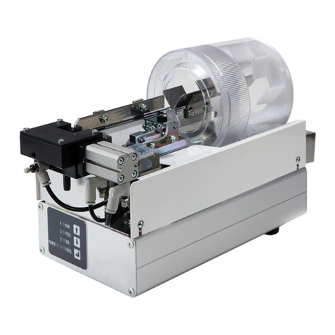
Nitto Seiko FF503H User manual

Vibratory Track Screw Feeder
FF/FM503H
Ver2
Instruction Manual
(For system
version
02.02、02.03)
FF503H type
Assembly Machine Division
NITTO SEIKO CO., LTD.

【Notes】
(1)All rights reserved. No part of or whole of this may be reproduced, stored in a
retrieval
system, or transmitted in any form or by any means without the prior written
permission of Nitto Seiko Co., Ltd.
(2)By provision of operating manual recorded on CD-ROM, you shall be deemed to have
agreed to the Terms and Conditions written in “readme.txt” on it.
(3)Contents of this manual are subject to update without notice according to
specification change of the products.
(4)Unique nouns like the product name indicated in this brochure are registered or not
registered trademark of each company.

Vibratory Track Screw Feeder FF/FM503H ver2
i
Preface
Thank you very much for your purchase of vibratory track screw feeder “FF/FM503H” (hereafter called
“FF/FM503H”). This FF/FM503H screw feeder, allowing optimal alignment and feeding of screws depending
on the type of screws, has characteristics shown below.
(1) It is applicable to main commercial supply voltage used worldwide.
(2) The intermediate plate type hopper is driven by the stepping motor, and the vibrator is controlled by
the inverter unique to Nitto Seiko.
This FF/FM503H does not comply with the CE marking. If you want to purchase a CE-compliant machine,
order the FF/FM503H-E that complies with the CE marking.
●Keep this instruction manual for your later reference.
If you need to order a new instruction manual because, for example, you have lost this instruction manual,
make a note of your machine serial number and contact our sales agent or your nearest sales office of
Nitto Seiko Co., Ltd.
●Specifications may be subject to alterations for improvement in the product without notice. The
manual may also be subject to changes with the alteration without any notice.
Marks and pictographs used in this manual
DANGER
Inappropriate handling may lead to imminent serious accidents (death or
serious injury).
WARNING
Inappropriate handling may lead to serious accidents (death or serious injury).
CAUTION
Inappropriate handling may lead to injury, physical damage, or damage to the
product.
References follow this mark.
!
OFF
Meanings of pictographs
(Examples)
This pictograph
means necessity of
paying attention.
This pictograph
means don'ts.These pictographs
mean musts.

Vibratory Track Screw Feeder FF/FM503H ver2
ii
For safe use
Prior to use of this product (installation, connection, operation, maintenance, and inspection), fully read and
understand the safety precautions shown below, and appropriately handle it with care. Note that it is very
difficult to cover all the detailed precautions for safety by this manual only, and proper judgment on safety and
actions taken by operators are very important for prevention of possible hazards.
●Always observe the instructions following the marks of DANGER, WARNING, and
CAUTION.
Inappropriate installation, power supply, connection of earth, signal communication with outside,
maintenance, or inspection may cause unexpected accidents, shorter service life, degraded performance,
damage to product, or accidents leading to a loss of life or injuries, occasionally. Be sure to read this
manual before usage for appropriate use.
Serious accidents may occur even if instructions following the mark of CAUTION are not observed,
depending on the situations.Always observe the instructions including very important information.
DANGER
!
DANGER
Always connect the earth cable led from theAC input power cable to the grounding
electrode.
Otherwise, fires, electric shocks, accidents, or faults
may occur. Furthermore, we cannot guarantee the
performance of the product.
Electric wires in the colors shown in the figure on the
right are connected to the terminals of the AC input
power cable plug. Thus, always connect the electric
wires to the specified terminals when wiring on the
side of receptacle to be prepared by customers.
If no plug is provided, be sure to connect the electric
wires to the specified terminals according to the colors
of wires shown in the figure on the right.
!WARNING
WARNING
DO NOT disassemble or modify the product.
Otherwise, fires, electric shocks, or accidents may occur. If the product is disassembled or
modified, we cannot take any responsibility for all the troubles, including degradation of
performance, since the disassembled or modified product is out of our guaranteed coverage. Note
that covers or safety shields are omitted in the figures in this manual for convenience of
descriptions of details.
WARNING
OFF
Shut down the power immediately if any fault is found in the machine.
If any fault, including fume, abnormal odor and noise, is found in the machine, turn off the power
switch first, then shut down the power supplied, and ask sales agent or your nearest sales office of
Nitto Seiko Co., Ltd. for repair. Use of the faulty machine without repair may cause fires, electric
shocks, or accidents.
WARNING
DO NOT apply voltage out of specifications to this product.
Otherwise, fires, electric shocks, accidents, or malfunctions may occur.
Input power voltage: Single phase, 100 to 240 VAC 50/60 Hz
Power capacity: max. 50 VA
Without plug
L (Brown) Phase/application
N (Pale blue) Neutral
PE (Yellow/Green) Earth
(The colors shown above are those of the wires.)
With plug (Only for 100 VAC in Japan)
(The colors shown above are those of the wires.)
N (White)
Neutral
PE (Yellow/Green)
Earth
L (Black)
Phase/application

Vibratory Track Screw Feeder FF/FM503H ver2
iii
WARNING
Satisfy the conditions required for the operating environment.
Otherwise, fires, electric shock, or faults may occur. Use this product at a 1000 m or less height in
ordinary indoor environment, satisfying the conditions shown below.
Free from corrosive or flammable gas
The atmosphere is free from conductive powder, including iron powder.
Well-ventilated and free from dusts
No vibration or heat source is nearby placed.
No fluid, including water, is splashed with the product.
Free from soot
The environmental temperature is within a range from 0 to 40°C.
The relative humidity is within a range from 30 to 90% RH, free from freezing or dew
condensation.
No flammable is nearby placed.
Easy to be checked or cleaned
Free from strong electric or magnetic field
WARNING
Always shut down the power source before providing or changing wiring.
Otherwise, electric shocks (including residual voltage), accidents, or malfunctions may occur.
NEVER touch any of the connecting terminals of theAC inlet installed on the back panel for at
least one minute after the power supply is shut off.
WARNING
Use the machine under the specified air pressure.
Use of it under the air pressure exceeding the specified level may cause burst or breakdown of
pneumatic equipment or jumping of a screw fed by compressed air, leading to injuries (if it hits
your eye, you may lose your sight) or damage to peripheral equipment.
WARNING
Do not look into the escapement unit or screw feeding hose inadvertently or direct them to
anyone.
Otherwise, a screw fed from the escapement unit or screw feeding hose by compressed air may
jump off, leading to injuries (if it hits your eye, you may lose your sight) or damage to peripheral
equipment.
WARNING
When connecting the screw feeding hose, fix the both ends securely.
If it comes off, a screw fed by compressed air may jump off from an end of the hose, leading to
injuries (if it hits your eye, you may lose your sight) or damage to peripheral equipment.
WARNING
OFF
MPa
0
0.1
0.2 0.4
0.3
0.5
0.6
Ensure that the power and air supply are shut down before maintenance or inspection of the
machine.
Before restarting it after a long interval, completely clean and check it, and perform test run
to ensure that it is free from any fault.
Otherwise, electric shocks, accidents, or malfunctions may occur.
WARNING
OFF
MPa
0
0.1
0.2 0.4
0.3
0.5
0.6
In principle, do not adjust the machine being energized with the cover removed.
The machine is adjusted optimally at the factory before shipping.
Otherwise, fires, electric shocks, accidents, or malfunctions may occur.
If you adjust the machine with the cover removed by necessity and any trouble occurs, Nitto
Seiko assumes no responsibility for it because it is not covered by our warranty.
(Note that the procedures for adjusting the machine with the cover removed described in “7.9.
Adjustment of photoelectric sensor” to “7.14.Adjustment of clearance” are shown for
convenience sake in order for you to understand the characteristics of the machine.)

Vibratory Track Screw Feeder FF/FM503H ver2
iv
!CAUTION
CAUTION
DO NOT touch any of moving parts while the machine is running.
Otherwise, injuries or malfunctions may occur.
CAUTION
Always use the connecting cables specified by us. When handing them, pay extreme
attention.
Carefully lay connecting cables to prevent them from being caught by your foot or pinched by a
heavy object placed on it. DO NOT forcibly pull or twist them, but handle them carefully. Use of
cables that are not specified by us or damaged or disconnected cables may cause fires, electric
shocks, accidents, or malfunctions.
CAUTION
Be sure to use the fuses designated by us.
Otherwise, fires, electric shocks, accidents, or malfunctions may occur.
CAUTION
When installing this product to a high place, provide measures against tipping and
dropping.
Otherwise, you may suffer from injuries, or the machine may be damaged or malfunctioned.
CAUTION
DO NOT remove the rubber foot to fix the unit directly on a surface.
Otherwise, the straightforward rail may not be vibrated enough to feed the screws properly.

Vibratory Track Screw Feeder FF/FM503H ver2
v
Check at arrival of delivered product
Check the following items when the product is delivered to you.
Items to be checked Remarks
(1) Ensure that the correct product has
been delivered to you. Check the “Model” on the nameplate.
(2) Accessories
Ensure that the connecting cables
are attached.
Ensure that the screw feeding
hose is attached.
Ensure that the other accessories
are attached.
a) Connecting cable
(Refer to 2.2 Designations and models of
connecting cables”.)
AC input power cable: 1
(Because the model FF503H-AC varies depending on the
specifications of the ordered machine, check if the correct cable is
attached while referring to the separate part list.)
External I/O cable: 1
(Because the model FF503H-IC varies depending on the
specifications of the ordered machine, check if the correct cable is
attached while referring to the separate part list.)
b) Screw feeding hose: 1 pc. (2 pcs. in the case of feeding 2
pcs.)
(Because the number of hoses varies depending on the specifications
of the ordered machine, check if the number of hoses is correct while
referring to the separate part list.)
c) Other accessories
(Because the other accessories vary depending on the specifications
of the ordered machine, check if the correct accessories are attached
while referring to the separate part list. No tools are attached.)
(3) Ensure that all of the spares are
attached. Fuse: 2 pcs.
(Refer to “2.3.2 Back face” and “12.1 Specifications”.)
(4) Ensure that the machine is free from
damages. Check for damages occurred during transportation.
(5) Ensure that the covers are attached. Ensure that all the covers shown in the figure below are
attached.
(6) Ensure that screws are tightened. Check for looseness of the screws indicated by arrows shown
in the figure below with using a screwdriver.
Immediately contact the sales agent, for which you purchased the product, or your nearest sales office of Nitto
Seiko Co., Ltd., if there is any fault in items to be checked from (1) to (6) above.
Fig.1

Vibratory Track Screw Feeder FF/FM503H ver2
Contents
1.
Outline of FF/FM503H......................................................................................................1
1.1. Features of FF/FM503H ....................................................................................................1
1.2. Structure of FF/FM503H....................................................................................................1
2.
Types of FF/FM503H........................................................................................................2
2.1. Model................................................................................................................................. 2
2.2. Designations and models of connecting cables................................................................2
2.3. Designations of components.............................................................................................3
2.3.1.
Front face.....................................................................................................................................3
2.3.2.
Back face.....................................................................................................................................3
3.
Installation of FF/FM503H...............................................................................................4
3.1. Operating environment...................................................................................................... 4
3.2. Installation.......................................................................................................................... 4
4.
Preparation of operation.................................................................................................5
4.1. Connection of screw feeding hose....................................................................................5
4.2. Connection of connecting cable ........................................................................................ 5
4.3. Air supply...........................................................................................................................7
4.3.1.
When the filter regulator is installed.............................................................................................7
4.3.2.
When the filter regulator is not installed.......................................................................................7
4.3.3.
For hand driver type of air driver specification.............................................................................7
4.4. Loading screws..................................................................................................................7
4.5. Turning on power............................................................................................................... 8
4.5.1.
Checking of LED light ..................................................................................................................8
4.5.2.
Checking of operation..................................................................................................................8
4.6. Checking of screw feeding ................................................................................................9
5.
Start of operation.............................................................................................................9
5.1. For automatic type.............................................................................................................9
5.2. For hand driver type........................................................................................................... 9
5.3. For screw taking-out type .................................................................................................. 9
6.
Explanation of operation ..............................................................................................10
6.1. Operation of each part..................................................................................................... 10
6.1.1.
Hopper track..............................................................................................................................10
6.1.2.
Vibrator......................................................................................................................................10
6.1.3.
Screw feeding............................................................................................................................10
6.1.3.1.
For automatic type.............................................................................................................10
6.1.3.2.
For hand driver type ..........................................................................................................10
6.1.4.
Screw taking-out........................................................................................................................ 11
6.1.4.1.
For screw taking-out type.................................................................................................. 11
6.2. Operation time chart.........................................................................................................11
6.2.1.
Screw feeding............................................................................................................................ 11
6.2.2.
Screw taking-out........................................................................................................................12
7.
Instructions on adjustment of each part......................................................................12
7.1. Adjustment of air pressure (Applicable only when a filter regulator is installed).............13
7.2. Lubricator oil drop adjustment (Applicable only when the lubricator is installed) ........... 13
7.3. Adjustment of screw feeding time....................................................................................13

Vibratory Track Screw Feeder FF/FM503H ver2
7.4. Adjustment of screw feeding air flow rate........................................................................14
7.5. Escapement unit left and right operation speeds adjustment.........................................15
7.6. Adjustment of vibrator vibration frequency......................................................................15
7.7. Setting of vibrator vibration strength................................................................................16
7.8. Adjustment of vibrator vibration time...............................................................................16
7.9. Adjustment of photoelectric sensor.................................................................................16
7.10. Adjustment of hopper track, fixed track and track...........................................................17
7.11. Adjustment of kick plate...................................................................................................18
7.12. Adjustment of track and upper guide...............................................................................18
7.13. Adjustment of track and escapement unit....................................................................... 19
7.14. Adjustment of clearance..................................................................................................20
8.
Setup procedures..........................................................................................................21
8.1. Setup panel......................................................................................................................21
8.1.1.
Appearance of setup panel........................................................................................................21
8.1.2.
Functions of setup keys.............................................................................................................21
8.1.3.
Indication by LEDs.....................................................................................................................22
8.2. Setup and adjustment procedures...................................................................................23
8.2.1.
Before setup ..............................................................................................................................23
8.2.2.
Outline of operation in setup and adjustment mode...................................................................23
8.2.3.
FF/FM503H Setup and adjustment mode function list...............................................................24
8.3. Setup and adjustment items............................................................................................28
8.3.1.
Operation parameter setup........................................................................................................28
8.3.2.
Equipment parameter setup.......................................................................................................31
8.3.3.
Special mode setup ...................................................................................................................33
8.3.3.1.
Parameter initializing mode...............................................................................................34
8.3.3.2.
I/O check mode.................................................................................................................34
8.3.3.3.
Version check mode..........................................................................................................36
9.
Maintenance and check................................................................................................37
9.1. Filter regulator..................................................................................................................37
9.2. Lubricator......................................................................................................................... 37
9.3. Inside the FF/FM503H.....................................................................................................37
9.4. Screw feeding hose.........................................................................................................38
10.
Failure cause and corrective measure.........................................................................38
10.1. Malfunction.......................................................................................................................38
10.2. Other malfunctions...........................................................................................................39
10.3. Troubleshooting............................................................................................................... 40
10.4. Repair...............................................................................................................................41
11.
Guarantee ......................................................................................................................41
11.1. Warrantee ........................................................................................................................ 41
11.2. Warranty period ...............................................................................................................41
11.3. Exclusion from warranty coverage..................................................................................41
12.
Appendix........................................................................................................................42
12.1. Specifications................................................................................................................... 42
12.2. External I/O receptacle (CN IO) pin layout......................................................................43
12.2.1.
External I/O receptacle (CN IO) pin layout (SINK (NPN) type) ..................................................43
12.2.2.
External I/O receptacle (CN IO) pin layout (SOURCE (PNP) type)............................................45

Vibratory Track Screw Feeder FF/FM503H ver2
12.2.3.
Descriptions of external I/O receptacle (CN IO) signals.............................................................46
12.3. Pin layout of receptacle (CN FEED) (hand driver type) for screw feeding......................47
12.4. Pin layout of 3P receptacle (CN SH) for connection of “SH300”..................................... 47
12.5. Electric circuit diagram (FF503H, FM503H).................................................................... 48

Vibratory Track Screw Feeder FF/FM503H ver2
1
1. Outline of FF/FM503H
1.1. Features of FF/FM503H
FF/FM503H automatically feeds screws as shown below before screw tightening operations.
(1) Screws loaded into the basket are scooped up by swaying of the hopper track driven by the stepping
motor, and fed onto the track.
(2) The track is slightly and horizontally vibrated by the vibrator. Screws on the track are gradually
moved by the slight vibration until they arrive at the escapement unit.
(3) After screws arrive at the escapement unit, the screw feeding solenoid valve is operated by the screw
feeding signal from the outside, and they are fed to the chuck unit of the driver unit by compressed air
through the screw feeding hose from the escapement unit.
(4) Screws fed to the chuck unit by compressed air are tightened until they are screwed into works.
1.2. Structure of FF/FM503H
The main structure of FF/FM503H is as shown in the figure below.
Track
Hopper track
Kick plate
Partition plate
Fixed track
Screw feeding
Belt
Stepping motor
Vibrator
Hose joint
Escapement unit
Basket
Photoelectric sensor
Upper guide
(Hopper track driving motor)
solenoid valve
Fig.2

Vibratory Track Screw Feeder FF/FM503H ver2
2
2. Types of FF/FM503H
2.1. Model
Models of the FF/FM503H are defined by substituting the specified symbols for (1) to (3) shown below.
FF503H-(1)(2)(3): Automatic type (including screw taking-out type)
FM503H-(1)(2)(3): Hand driver type
Symbols Details
(1)(2) Escapement unit type
S1 4K20 (for feeding 1 pc. only)
D1 4G00 (for feeding 1 pc.)
D2 4G00 (for feeding 2 pcs.)
SP Special
(3) External I/O type
N SINK (NPN) type
P SOURCE (PNP) type
X None
2.2. Designations and models of connecting cables
Three types of the dedicated connecting cables shown below are applicable to the FF/FM503H.
Designations Models
(1) AC input power cable
Dedicated cable to supply power to
FF/FM503H
(Standard accessory)
(2) External I/O cable
Dedicated cable to connect external
controllers to FF/FM503H
(Only the plug is provided as a standard
accessory for the standard machine of
automatic type. Plug with cable is
optional.)
(Both the plug and the plug with cable
are optional for the hand driver type.)
(3) Screw feeding signal cable
It is a dedicated cable to be connected to
the hand driver tool. (Hand driver type)
Connected directly to the hand driver tool

Vibratory Track Screw Feeder FF/FM503H ver2
3
2.3. Designations of components
2.3.1. Front face
Fig.3
Fig.4
(1) Setup panel
This panel is intended for indication of power ON and setup
and display of modes and parameters.
(2) POWER LED
This LED lights up when the power is supplied. (Color:
Green)
(3) Controller status LEDs
These LEDs indicate the status of controller. (Color: Orange)
They indicate the setup statuses while the machine is in the
setup or adjustment mode.
(For details, refer to “8. Setup procedures”.)
(4) Setup keys
Any intended functions or setup values could be selected with
these keys while the machine is in the setup mode.
[ ]: UP key (Item number is increased by one, setup value is
increased by one)
[ ]: DOWN key (Item number is decreased by one, setup
value is decreased by one)
[]: ENTER key (Confirmation of item number or change in
setup value)
(5) Screw feeding receptacle (3P) (CN FEED) (Hand driver
type)
This receptacle is intended for connection of the screw feeding
signal cable for the hand driver type. It is not provided for the
automatic type.
(6) Air supply port for air driver (Hand driver type)
This air supply port is intended to supply air to the hand driver
tool (air driver).
(7) Escapement unit
This unit feeds screws by compressed air.
2.3.2. Back face
Fig.5
(8) Power switch (SW1)
This switch turns ON/OFF the FF/FM503H.
(9) Fuse (Contained in fuse holders FU2 and FU3)
0215004. MXP made by Littelfuse
(5 × 20 mm 250 VAC 4 A time lag type complying with RoHS)
(10) AC inlet (NF1)
Our specifiedAC input power cable should be connected to
this inlet. Connect the plug of the AC input power cable to the
specified receptacle. (For details, refer to “For safe use”.)
(11) External I/O receptacle (CN IO) (9P)
This receptacle is intended for connection of our specified
external I/O plug (or external I/O cable) for automatic type.
Connect the other end of the external I/O cable to the
programmable logic controller (PLC) etc. stored in the separate
external controller (to be prepared by customers). (This
receptacle is not attached to the hand driver type. However, it
can be attached optionally.)

Vibratory Track Screw Feeder FF/FM503H ver2
4
(12) a.Air supply port (for the automatic type)
b. Air supply port (for the hand driver type or (13) attached
optionally)
Connect the air tube with 8 mm outer diameter.
(13) Filter regulator
Set this regulator to the specified pressure. This filter regulator
is not attached to the automatic type. However, it can be
attached optionally.
(14) Lubricator
This lubricator supplies lubricating oil to the hand driver tool.
It is not attached to the automatic type and the hand driver type
of electric driver specification. However, the lubricator can be
attached optionally.
(15) 3P receptacle for connecting SH300 (CN SH)
This is a 3P receptacle for connecting the optional rotary drum
auxiliary hopper SH300.
3. Installation of FF/FM503H
3.1. Operating environment
WARNING Satisfy the conditions required for the operating environment.
Otherwise, fires, electric shocks, accidents, or malfunctions may occur.
For the operating environment, refer to “Preface”, “For safe use”, and
“12.1 Specifications”.
3.2. Installation
Install the FF/FM503H on a solid and horizontal floor (or table) so that screws can be fed from the top face,
setup can be carried out from the front face, and the power switch can be operated from the back face, for
correct vibration to be performed for screw alignment (see the figure shown below). Installation of the
machine onto the place where measures against vibration are provided or onto a slope may cause troubles in
screw feeding. Provide some measures against tipping or dropping, if necessary.
CAUTION Do not remove the rubber foot to fix the unit directly on a surface.
Otherwise, the straightforward rail may not be vibrated enough to feed the screws properly.
Fig.6

Vibratory Track Screw Feeder FF/FM503H ver2
5
4. Preparation of operation
Before starting operation, make preparations as follows:
4.1. Connection of screw feeding hose
WARNING
When connecting the screw feeding hose
(1) Make sure that the air supply is shut down.
(2) Fix both ends securely.
If the screw feeding hose comes off with air
being supplied, a screw fed by compressed air
may jump off from an end of the hose, leading
to injuries (if it hits your eye, you may lose
your sight) or damage to equipment around the
machine. To ensure safety, do not look into the
screw feeding hose inadvertently or direct them
to anyone.
(3) Take care not to have your hand or finger
cut as a result of touching the edge of the
hose connector or the edge face of the screw
feeding hose.
Fig.7
After inserting the screw feeding hose over the hose connector, be sure to clamp the hose with a hose band
to prevent it from being disconnected.
If it is difficult to insert the hose, spread the end using a tapered tool.
4.2. Connection of connecting cable
WARNING
Always connect the earth cable led from theAC input power cable to the grounding
electrode.
Otherwise, fires, electric shocks, accidents, or faults may occur. Furthermore, we cannot
guarantee the performance of the product.
(Refer to “For safe use”.)
WARNING
Do not apply a voltage out of specifications to this product.
Otherwise, fires, electric shocks, accidents, or malfunctions may occur.
WARNING
Always shut down the power source before providing or changing wiring.
Otherwise, electric shocks (including residual voltage), accidents, or malfunctions may
occur. Never touch any of the connecting terminals of the AC inlet installed on the back
panel for at least one minute after the power supply is shut off.
CAUTION
Always use the connecting cables specified by us. When handing them, pay extreme
attention.
Carefully lay connecting cables to prevent them from being caught by your foot or
pinched by a heavy object placed on it. DO NOT forcibly pull or twist them, but handle
them carefully. Use of cables that are not specified by us or damaged or disconnected
cables may cause fires, electric shocks, accidents, or malfunctions.

Vibratory Track Screw Feeder FF/FM503H ver2
6
Connect the cables to the FF/FM503H in the following procedure.
(1) Confirm that the power switch of the FF/FM503H is turned off.
(2) Connect the cables securely to the specified positions as shown below. Be sure to tighten the fixing screws if
installed in the plugs.
(3) Customers should prepare the wiring at the receptacle side to which theAC input power cable plug is
connected. Be sure to connect each cable to a specified terminal. Check again if the voltage supplied to the
receptacle is as specified, if the power source capacity is sufficient and if the earth wire is connected to the
grounding electrode. (Refer to “For safe use”.)
Rear panelFront panel
Power supply
【To be prepared by customers】
Be sure to connect the earth wires to a
grounding electrode
(It differs in the
form of the cable
to be used)
External control
device such as a
programmable logic
controller(PLC)
Screw feeding switch of
hand driver tool
-
Screw feeding signal cable
AC input
power cable
External I/O cable
Connect the
plug of the
optional rotary
drum auxiliary
hopper SH300
power cable
with a plug
(Necessary for Only for hand
driver type)
Fig.8

Vibratory Track Screw Feeder FF/FM503H ver2
7
4.3. Air supply
WARNING
Use the machine under the specified air pressure.
Use of it under the air pressure exceeding the specified level may cause burst or
breakdown of pneumatic equipment or jumping of a screw fed by compressed air, leading
to injuries (if it hits your eye, you may lose your sight) or damage to peripheral
equipment.
4.3.1. When the filter regulator is installed
Connect the air supply line in the factory to the filter regulator
on the rear surface of the FF/FM503H with an air tube of a
diameter φ8. The air to be supplied should be clean at a pressure
of 0.5–0.6 MPa.
After connecting the tube, rotate the pressure adjustment handle
of the filter regulator so that the pressure gauge indicates
0.4–0.5 MPa.
(Refer to “7.1Adjustment of air pressure”.)
4.3.2. When the filter regulator is not installed
Connect the air supply line in the factory to the filter regulator
on the rear surface of the FF/FM503H with an air tube of a
diameter φ8. The air to be supplied should be clean at a pressure
of 0.4–0.5 MPa.
Caution: If the amount of air becomes insufficient in the
factory air supply line, a trouble with screw supply
will happen. Ensure adequate amount of air supply.
Furthermore, improve the air supply path if the
pressure drops excessively during operation.
Fig.9
Fig.10
4.3.3. For hand driver type of air driver specification
In the case of the hand driver type of air driver specification, connect an air tube for hand driver tool (outer
diameter φ8) to the air supply port for air driver on the front face of the FF/FM503H.
4.4. Loading screws
Opening the screw inlet cover, load the screws conforming to
FF/FM503H specifications into the basket. Do not load the
screws exceeding the height of the partition plate (red mark).
Close the screw inlet cover after you have loaded the screws.
Fig.11

Vibratory Track Screw Feeder FF/FM503H ver2
8
CAUTION
Precautions about the screws to be loaded into the basket
(1) Before loading the screws, be sure to check if they conform to the specification (size,
head type, etc.) specified when the FF/FM503H was ordered. Otherwise, machine
failures or incorrect feeding may happen.
(2) Do not use used screws, magnetized screws, and screws contaminated with oil.
Otherwise, machine failures or incorrect feeding may happen.
(3) Do not load the screws in the basket exceeding the height of the partition plate upper
surface (red mark).
Otherwise, machine failures, jamming or incorrect feeding may happen.
(4) Close the screw-inlet cover after loading the screws so as not to mix foreign
materials into the screws.
Otherwise, machine failures, jamming or incorrect feeding may happen.
CAUTION
Precautions in taking out the screws from the basket
Take care not to have your hand cut with iron powder etc.
4.5. Turning on power
CAUTION
Precautions in turning on the power switch
(1) To turn on the machine again after turning it off, be sure to wait for at least 5 seconds
after the POWER LED (green) goes off before turning on the power switch.
(2) Do not turn on/off the power many times in a short time.
Otherwise, the useful time of the FF/FM503H may be reduced and failure may
happen.
4.5.1. Checking of LED light
Turn on the power switch on the rear surface of the unit, and check that the LEDs light up as shown in (1)–(4)
below:
(Refer to “2.3.1 Front face” and “8.1.1 Appearance of setup panel”.)
(1) The POWER LED (green) lights up on the set up panel.
↓
(2) The LEDs from LED1 (=1FREQ.) to LED4 (=4RUN) light up in a flash.
↓
(3) The LEDs from LED1 (=1FREQ.) to LED4 (=4RUN) light up in sequence.
↓
(4) The above-mentioned LEDs from LED1 (=1FREQ.) to LED4 (=4RUN) go off once.
↓
(5) “LED4 (=4RUN)” LED flashes. (On and off each for 0.1 sec)
4.5.2. Checking of operation
At the same time when the “LED4 (=4RUN)” starts to blink, the FF/FM503H performs the following
operations automatically.
(1) The screws loaded into the basket are scooped up by swaying of the hopper track driven by the
stepping motor, and fed onto the track.
↓
(2) Since the above-mentioned track is slightly and horizontally vibrated by the vibrator, the screws on the
track are gradually moved by the slight vibration until they arrive at the escapement unit.
↓

Vibratory Track Screw Feeder FF/FM503H ver2
9
(3) After the first screw reaches the escapement unit and when the screws that follow are aligned along
the track to the photoelectric sensor detection point, the hopper track stops swaying automatically.
4.6. Checking of screw feeding
After screws arrive at the escapement unit, the screw feeding solenoid valve is operated by the screw feeding
signal from the outside, and they are fed to the chuck unit of the driver unit by compressed air through the
screw feeding hose from the escapement unit. Attach a sensor to the screw feeding hose as necessary and
check if the screws are fed to the chuck unit correctly by compressed air. We have adjusted the screw feeding
to the specification. However, if a screw feeding failure happens, adjust the feeding. (Refer to “7.3
Adjustment of screw feeding time” and “7.4 Adjustment of screw feeding air flow rate”.)
5. Start of operation
5.1. For automatic type (Type:FF503H)
In sync with the screw tightening operation, input a screw feeding signal from an external control device, such
as a PLC, into the No. 7 pin of the FF/FM503H external I/O receptacle (CN IO). With this signal, the
FF/FM503H starts to feed screws by compressed air.
If you use the machine of this type, you need to set the type setting parameter (Pa.E1) to “Automatic type” in
advance. (For details of setup and adjustment mode, refer to “8.2.3 FF/FM503H Setup and adjustment
mode function list”.)
(Each machine is shipped from the factory with the parameters set in accordance with specified
specification.)
5.2. For hand driver type (Type:FM503H)
Connect the screw feeding signal cable of the hand driver tool to the screw feeding receptacle (CN FEED)
(hand driver type) of the FF/FM503H. When you tighten a screw with the hand driver tool (or when you
expand/contract the driver unit), the built-in switch of the driver unit is activated to input a screw feeding
signal to the FF/FM503H through the screw feeding receptacle (CN FEED) (hand driver type). With this signal,
the FF/FM503H starts to feed screws to the driver unit automatically.
IF you use this type, you need to set the type setting parameter (Pa.E1) to either “Hand driver type (micro
switch)” or “Hand driver type (reed switch)”. (For details of setup and adjustment mode, refer to “8.2.3
FF/FM503H Setup and adjustment mode function list”.)
(Each machine is shipped from the factory with the parameters set in accordance with specified
specification.)
5.3. For screw taking-out type
The escapement unit of the screw taking-out type differs in construction from that of the standard type; it is
equipped with a photoelectric sensor etc. in order to check whether there are screws in the taking-out position.
If you want to purchase the taking-out type, order the FF503H of taking-out type.
If you use this screw taking-out type, you need to set the type setting parameter (Pa.E1) to “Screw taking-out
type”. (For details of setup and adjustment mode, refer to “8.2.3 FF/FM503H Setup and adjustment mode
function list”.)
(Each machine is shipped from the factory with the parameters set in accordance with specified specification.)

Vibratory Track Screw Feeder FF/FM503H ver2
10
6. Explanation of operation
This chapter explains the operation of the major parts of the FF/FM503H. (Refer to “6.2 Operation time
chart” described below.)
6.1. Operation of each part
The operations of major parts are shown as follows. The (Pa.**) in the explanation represents a parameter
number that allows setting change or adjustment. For details of parameter setting, refer to “8. Setup
procedures”.
6.1.1. Hopper track
The hopper track starts swaying in a preset time (Pa.85) after the photoelectric sensor on the track is turned on
(by the absence of screws), and stops swaying in a preset time (Pa.86) after the photoelectric sensor is turned
off (by the presence of the screws).
If the swaying continues exceeding a preset time (2 minutes) with the photoelectric sensor staying ON, the
machine enters an intermittent operation mode with predetermined intervals (Pa.88 and Pa.89, which are
specified by the “Hopper track intermittent running ON time setting” and “Hopper track intermittent running
OFF time setting” respectively. If the swaying continues further for a long time (about 2 hours), the machine
enters a suspend mode assuming that there are no works (screws) in the basket. “LED4 (=4RUN)” LED on
the setup panel flashes at 1 second intervals. (Refer to “10.1 Malfunction”.) To exit from the suspend
mode, turn on the machine again or input the screw feeding signal.
6.1.2. Vibrator
The track vibrator starts vibration in a preset time (Pa.85) after the photoelectric sensor on the track is turned
on (by the absence of screws), and stops vibration in a preset time (Pa.86) after the photoelectric sensor is
turned off (by the presence of the screws).
Separately from the above-mentioned operation, this vibrator starts operation at the same time when the screw
feeding solenoid valve is activated, and continues until a preset time (Pa.87) expires after the screw feeding
solenoid valve stops. This is a preparation for next feeding.
6.1.3. Screw feeding
6.1.3.1. For automatic type
The screw feeding solenoid valve and the track driving vibrator (to be more precise, the screw feeding signal
ON time + Pa.87 for the track driving vibrator) continue operations (irrespective of Pa.41) while a screw
feeding signal is being input into the No. 7 pin of the external I/O receptacle (CN IO).
6.1.3.2. For hand driver type
With the screw feeding signal from the switch in the hand driver tool, the screw feeding solenoid valve and the
track driving vibrator (to be more precise, Pa.41 + Pa.87 for the track driving vibrator) start operations for a
preset time (Pa.41).
(1) For hand driver type (micro switch)
Such a contact is used for the screw feeding signal that turns ON during screw tightening operation.
When this contact turns OFF →ON →OFF, the screw feeding starts and the screw feeding solenoid
valves and the track driving vibrator (to be more precise, Pa.41 + Pa.87 for the track driving vibrator)
operate for a preset time (Pa.41).
This manual suits for next models
1
Table of contents
Other Nitto Seiko Industrial Equipment manuals
Popular Industrial Equipment manuals by other brands
Mechanical Advantage
Mechanical Advantage Sambo SB-SR Series User instructions

ABB
ABB Sace TMAX XT XT4 ELECTRONIC Disassembly instructions
ProMinent
ProMinent Ultromat AFP Series Assembly and operating instructions
EASTMAN
EASTMAN 1050VB installation instructions

Mitsubishi Electric
Mitsubishi Electric MELDAS MDS-B Series instruction manual

Falcon
Falcon PLUS E3407 Installation and servicing instructions
