Niuli Maxiton GTJZ Series User manual
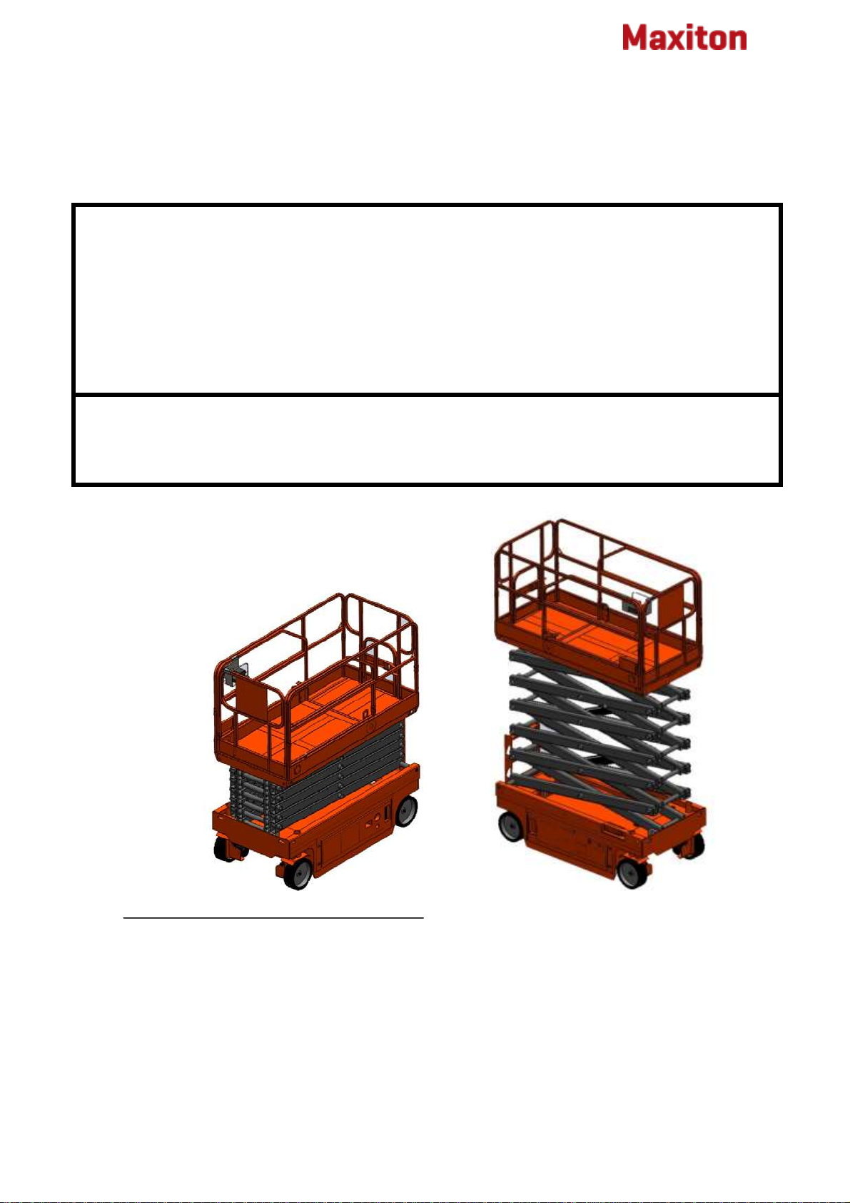
Self-propelled Scissors
Work Platform
Important
Read, understand and obey the safety rules and operating
instructions in the GTJZ03/34/06/08/10/12/14 Operator's
Manual before attempting any maintenance or repair
procedure.
This service manual covers the GTJZ03/04/06/08/10/12/14
models.
This manual provides detailed scheduled
maintenance information for the machine owner
and user. It also provides troubleshooting and
repair procedures for qualified service
professionals.
Basic mechanical, hydraulic and electrical skills are
required to perform most procedures. However,
several procedures require specialized skills, tools,
lifting equipment and a suitable workshop. In these
instances, we strongly recommend that
GTJZ Operation and Maintenance Manual

Operation and Maintenance Manual Second Edition A Brand of Niuli
1 MAXITON GTJZ
maintenance and repair be performed at the service center
which Niuli appointed.
Niuli has endeavored to deliver the highest degree of
accuracy possible. However, continuous improvement of
our products is a Niuli policy. Therefore product
specifications are subject to change without notice.
Readers are encouraged to notify Niuli of errors and
send in suggestions for improvement. All
communications will be carefully considered for future
printings of this and other manuals.
If you have any questions, please contact Niuli.
Tel: 0086-750-8311618
Fax: 0086 750 8382148
E-mail: niuli@chinaniuli.com
Website: www.chinaniuli.com
ADD:33#Nandong Industrical 3rd Park, Heshan city,
Guangdong Province, China.
Contents
Important Information .………………......1
Operation of Safety Rules ...…….....2
Maintenance of Safety Rules ........……7
Diagrams ……………...................... .8
Pre-operation Inspection …..………….......10
Maintenance ….………………...............11
Function Tests ……………….…………....12
Work Place Inspection ..………....….......14
Operating Instructions .…………............14
Transport and Lifting Instructions …..........17
Repair Procedures ...........................17
Theory of Operation ….…….......….....21
Scheduled Maintenance Procedures 22
Maintenance Inspection Report ……….. 25
Table A~E Procedures …........................26
Decals ………..….….….….……….............38
Specification ..………….........................39
Hydraulic and electric layout ..............40
Operation and Maintenance Manual Second Edition A Brand of Niuli
2 MAXITON GTJZ
Operation Of Safety Rules
Failure to obey the instructions and safety rules in this
manual will result in death or serious injury.
Do Not Operate Unless:
You learn and practice the principles of safe machine
operation contained in this operator's manual.
1 Avoid hazardous situations.
Know and understand the above principle before going on
to the next section.
2 Always perform a pre-operation inspection.
3 Always perform function tests prior to use.
4 Inspect the workplace.
5 Only use the machine as it was intended. You read,
understand and obey the manufacturer's instructions and
safety rules—safety and operator's manuals and
machine decals.
You read, understand and obey employer's safety rules and
worksite regulations.
You read, understand and obey all applicable governmental
regulations.
You are properly trained to safely operate the machine.
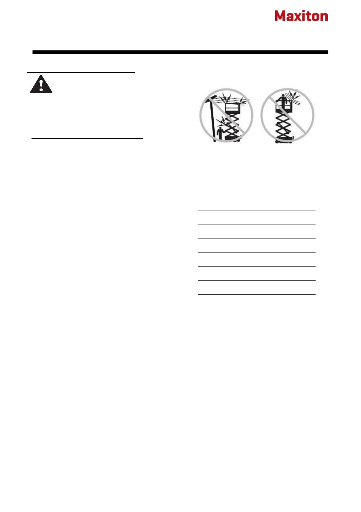
Electrocution Hazards
This machine is not electrically insulated and will
not provide protection from contact with or
proximity to electrical current.
Maintain safe distances from electrical power lines
and apparatus in accordance with applicable
governmental regulations and the following chart.
Voltage Minimum Safe
Phase to Phase Approach Distance
Meters
0 to 300V Avoid Contacting
300V to 50KV 3.05
50KV to 200 KV 4.60
200KV to 350 KV 6.10
350 KV to 500 KV 7.62
500 KV to 750 KV 10.67
750 KV to 1000 KV 13.72
Allow for platform movement, electrical line sway
or sag and beware of strong or gusty winds.
Keep away from the machine if it contacts
energized power lines.Personnel on the ground or
in the platform must not touch or operate the
machine until energized power lines are shut off.
Do not operate the machine during lightning or
storms.
Do not use the machine as a ground for welding.
Danger

Operation and Maintenance Manual Second Edition A Brand of Niuli
3 MAXITON GTJZ
Tip-over Hazards
Occupants and equipment must not exceed the maximum
platform capacity or the maximum capacity of the platform
extension.
Platform retracted
GTJZ06 230kg
GTJZ08 230kg
GTJZ10 320kg
GTJZ12 320kg
GTJZ14 230kg
Maximum occupants- ANSI and CSA 2
Maximum occupants - CE and Australia
Outdoor use 1
Indoor use only 2
230kg Extension only Platform only
115kg 115kg
GTJZ10/GTJZ12
320kg Extension only Platform only
115kg 205kg
Do not raise the platform unless the machine is on a
firm,level surface.
Do not depend on the tilt alarm as a level indicator. The tilt
alarm sounds on the chassis only when the machine is on a
slope.
If the tilt alarm sounds:
Lower the platform. Move the machine to a firm,level surface.
If the tilt alarm sounds when the platform is raised, use
extreme caution to lower the platform.
Do not alter or disable the limit switches.
Do not drive over 0.8km/h with the platform raised.
Do not operate the machine in strong or gusty
winds.
Do not increase the surface area of the platform or
the load. Increasing the area exposed to the wind
will decrease machine stability.
Do not drive the machine on or near uneven terrain
unstable surfaces or other hazardous conditions
with the platform raised.
Use extreme care and slow speeds while driving
the machine in a stowed position across uneven
terrain, debris, unstable or slippery surfaces and
near holes and drop-offs.
ANSI & CSA –2 person 500 N
CE –Indoor use only –2 person 500 N
CE –Outdoor use –1 person 200 N
Do not alter or disable machine components that
in any way affect safety and stability.
Do not place or attach fixed or overhanging loads
to any part of this machine.
GTJZ06/GTJZ08/GTJZ14
Do not push off or pull
toward any object outside of
the platform.
Maximum allowable manual force
Maximum capacity

Operation and Maintenance Manual Second Edition A Brand of Niuli
4 MAXITON GTJZ
Do not
place ladders or scaffolds in the platform or against any part
of this machine.
Do not modify or alter an aerial work platform. Mounting
attachments for holding tools or other materials onto the
platform, toe boards or guard rail system can increase the
weight in the platform and the surface area of the platform
or the load.
Do not replace items critical to machine stability with items
of different weight or specification.
Do not use the machine on a moving or mobile surface or
vehicle.
Be sure all tires are in good condition, castle nuts are
properly tightened and cotter pins are properly installed.
Do not use batteries that weigh less than the original
equipment. Batteries are used as counterweight and are
critical to machine stability.
Each battery must weigh 62 pounds / 28kg.
Do not use the machine as a crane.
Do not push the machine or other objects with the platform.
Do not contact adjacent structures with the platform.
Do not tie the platform to adjacent structures.
Do not place loads outside the platform perimeter.
Do not operate the machine with the chassis trays open.
Do not use the platform controls to free a platform that is
caught, snagged or otherwise prevented from normal
motion by an adjacent structure. All personnel must be
removed from the platform before attempting to free the
platform using the ground controls.
Fall Hazards
Occupants should wear a safety
belt or harness and comply with
applicable governmental
regulations.Attach the lanyard to
the anchor provided in the
platform. Do not sit, stand or
climb on the Platform guard rails.
Maintain a firm footing on the
platform floor at all times.
Do not climb down from the platform when
raised.
Keep the platform floor clear of debris.
Attach the platform entry chain or close the entry
gate before operating.
Do not operate the machine unless the guard rails
are properly installed and the entry is secured for
operation.。
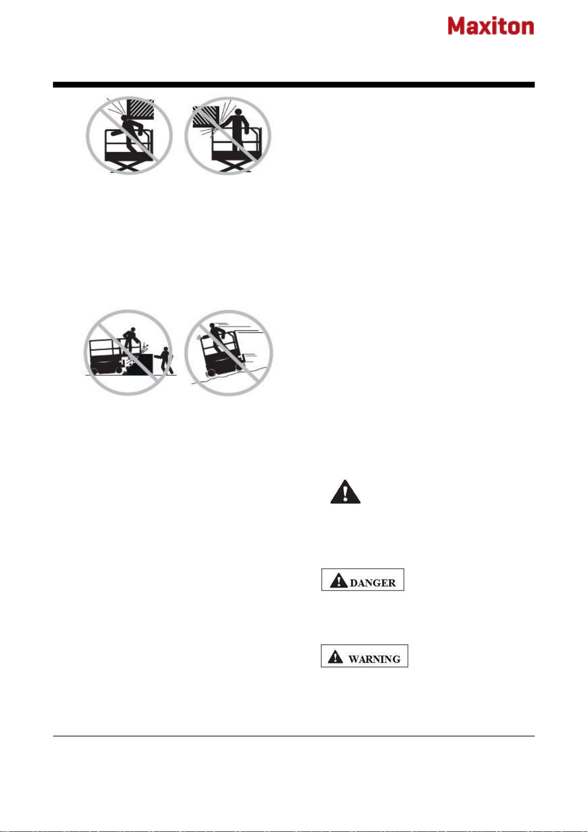
Collision Hazards
Be aware of limited sight distance and blind spots
when driving or operating.
Be aware of the extended
platform position when
moving the machine.
The machine must be on a
level surface or secured before releasing the
brakes.
It is recommended that operators wear an
approved hard hat when operating the machine.
Check the work area for overhead obstructions or
other possible hazards.
Operation and Maintenance Manual Second Edition A Brand of Niuli
5 MAXITON GTJZ
Be aware of crushing hazards when grasping the platform
guard rail.
Observe and use the color-coded direction arrows on the
platform controls and platform decal plate for drive and steer
functions.
No stunt driving or horseplay while operating a machine.
Do not lower the platform unless the area below is clear of
personnel and obstructions.
Limit travel speed according to the condition of the ground
surface, congestion, slope, location of personnel, and any
other factors which may cause collision.
Do not operate a machine in the path of any crane or moving
overhead machinery unless the controls of the crane have
been locked out and/or precautions have been taken to
prevent any potential collision.
Crushing Hazards
Keep hands and limbs out of scissors. Use common sense
and planning when operating the machine with the controller
from the ground. Maintain safe distances between the
operator, the machine and fixed objects.
Component Damage Hazard
Do not use the machine as a ground for welding.
Explosion and Fire Hazard
Do not operate the machine in hazardous locations or
locations where potentially flammable or explosive gases or
particles may be present.
Damaged Machine Hazards
Do not use a damaged or malfunctioning machine.
Conduct a thorough per-operation inspection of the
machine and test all functions before each work
shift. Immediately tag and remove from service a
damaged or malfunctioning machine.
Be sure all maintenance has been performed as
specified in this manual and the appropriate
service manual.
Be sure all decals are in place and legible.
Be sure the operation, safety, and responsibilities’
manuals are complete, legible and in the storage
container located on the platform.
Bodily Injury Hazard
Do not operate the machine with a hydraulic oil or
air leak. An air leak or hydraulic leak can penetrate
and/or burn skin.
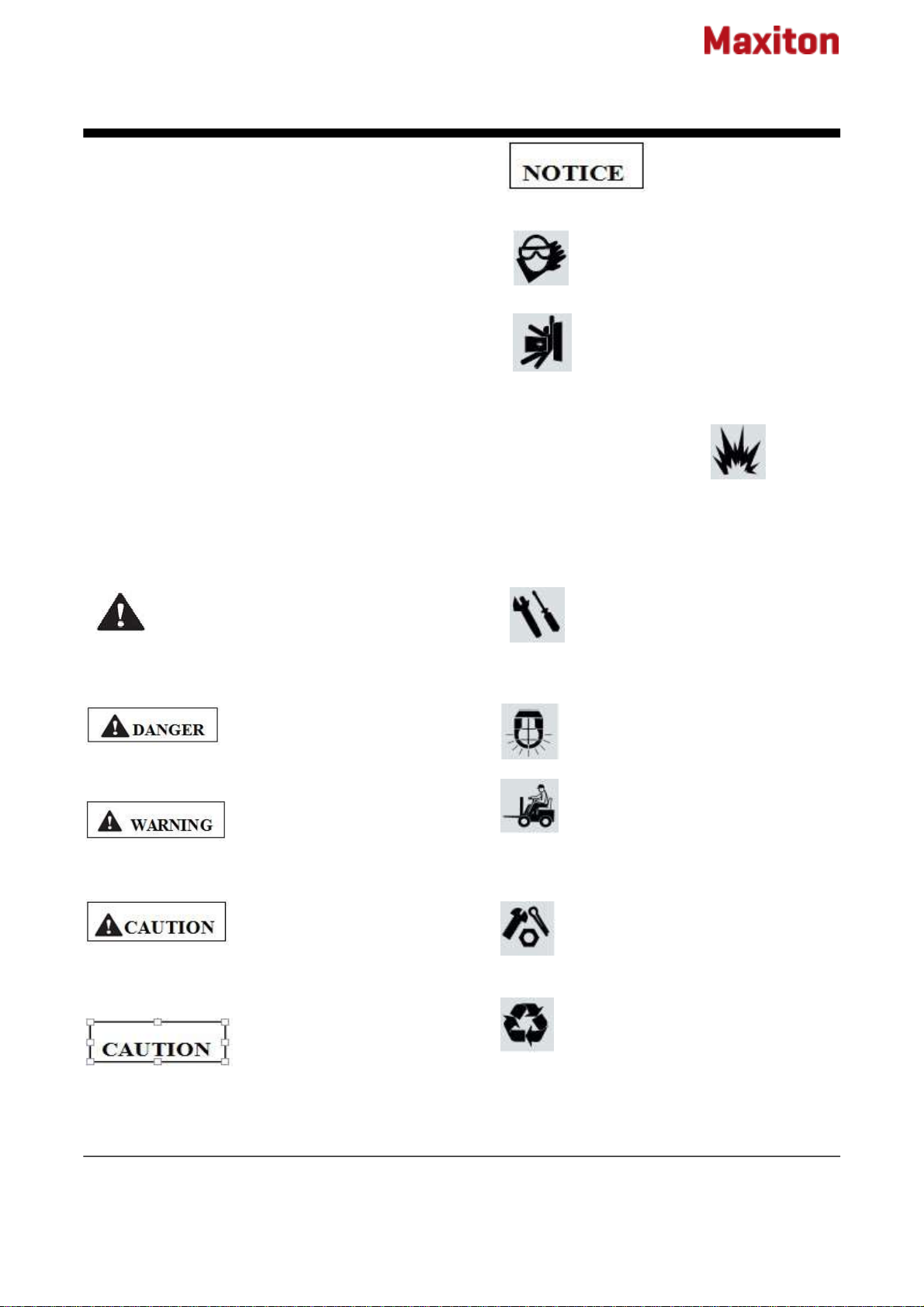
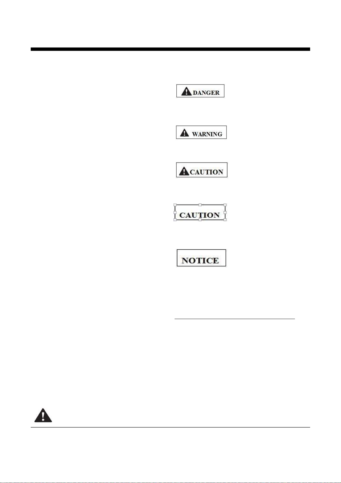
Decal Legend
Niuli product decals use symbols, color coding
and signal words to identify the following:
Safety alert symbol!used to alert personnel
to potential personal injury hazards. Obey all safety
messages that follow this symbol to avoid possible
injury or death.
Red!Used to indicate the
presence of an imminently hazardous situation
which,if not avoided, will result in death or serious
injury.
Orange!used to indicate
the presence of a potentially hazardous situation
which,if not avoided, could result in death or
serious injury.

Operation and Maintenance Manual Second Edition A Brand of Niuli
6 MAXITON GTJZ
Yellow with safety alert symbol! used
to indicate the presence of a potentially hazardous situation
which, if not avoided, may cause minor or moderate injury.
Yellow without safety alert
symbol!used to indicate the presence of a potentially
hazardous situation which, if not avoided, may result in
property damage.
Green!used to indicate operation or
maintenance information.
Battery Safety Burn Hazards
Batteries contain acid. Always wear protective clothing and
eyewear when working with batteries.
Avoid spilling or contacting battery acid. Neutralize battery
acid spills with baking soda and water. Do not expose the
batteries or the charger to water or rain during charging.
Explosion Hazards
Keep sparks, flames and lighted
tobacco away from batteries. Batteries
emit an explosive gas.
The battery tray should remain open
during the entire charging cycle.
Do not contact the battery terminals or the cable clamps with
tools that may cause sparks.
Component Damage Hazard
Do not use any battery charger greater than 24V to charge
the batteries.
Electrocution Hazards
Connect the battery charger to
a grounded, AC 3-wire
electrical outlet only. Inspect
daily for damaged cord, cables
and wires. Replace damaged
items before operating.
Avoid electrical shock from contact with battery
terminals. Remove all rings, watches and other
jewelry.
Tip-over Hazard
Do not use batteries that weigh less than the
original equipment. Batteries are used as
Counterweight and are critical to machine
stability Each battery must weigh 65 pounds / 28
kg.
Lifting Hazard
Use the appropriate number of people and proper
lifting techniques when lifting batteries.
Maintenance of Safety Rules
Danger
Failure to obey the instructions and safety rules in
this manual, will result in death or serious injury.
Many of the hazards identified in the operator's
manual are also safety hazards when
maintenance and repair procedures are
performed.
Do Not Perform Maintenance
Unless:
➢You are trained and qualified to perform
maintenance on this machine.
➢You read, understand and obey:
Operation and Maintenance Manual Second Edition A Brand of Niuli
7 MAXITON GTJZ
-manufacturer’s instructions and safety rules -
employer’s safety rules and work site ‘s regulations
-applicable governmental regulations
➢You have the appropriate tools, lifting equipment and a
suitable workshop.
Personal Safety
Any person working on or around a machine must be
aware of all known safety hazards. Personal safety and
the continued safe operation of the machine should be
your top priority.
Read each procedure thoroughly. This manual and the
decals, on the machine, use signal words to identify the
following:
This product decals use symbols, color coding and
signal words to identify the following:
Safety alert symbol!used to alert personnel
to potential personal injury hazards. Obey all safety
messages that follow this symbol to avoid possible injury
or death.
Red!Used to indicate the presence
of an imminently hazardous situation which,if not avoided,
will result in death or serious injury.
Orange!used to indicate the
presence of a potentially hazardous situation which,if not
avoided, could result in death or serious injury.
Yellow with safety alert symbol!
used to indicate the presence of a potentially hazardous
situation which, if not avoided, may cause minor or
moderate injury.
Yellow without safety alert
symbol!used to indicate the presence of a potentially
hazardous situation which, if not avoided, may result in
property damage.
Green!used to indicate
operation or maintenance information.
Be sure to wear protective eye wear
and other protective clothing if the
situation warrants it.
Be aware of potential crushing
hazards such as moving parts, free
swinging or unsecured components,
and lifting or placing loads. Always wear
approved
steel-toed shoes.
Workplace Safety
Be sure to keep sparks, flames and lighted
tobacco away from flammable and combustible
materials like battery gases and engine fuels.
Always have an approved fire extinguisher within
easy reach.
Be sure that all tools and working areas
are properly maintained and ready for
use. Keep work surfaces clean and
free of debris that could get into
machine
components and cause damage.
Be sure that your workshop or work
area is properly ventilated and well lit.
Be sure any forklift, overhead crane or
other lifting or supporting device is fully
capable of supporting and stabilizing the
weight to be lifted. Use only chains or
straps
that are in good condition and of ample
capacity.
Be sure that fasteners intended for one
time use (i.e., cotter pins and self-locking
nuts) are not reused. These components
may fail if they are used a second time.
Be sure to properly dispose of old oil or
other fluids. Use an approved container.
Please be environmentally safe.

Operation and Maintenance Manual Second Edition A Brand of Niuli
8 MAXITON GTJZ
1.Platform entrance door
2.Platform entrance bar
3.Platform of fence
4.Safety belt anchorage
5.Platform extension part
6.Platform extension part release the pedal
7.Steering wheel
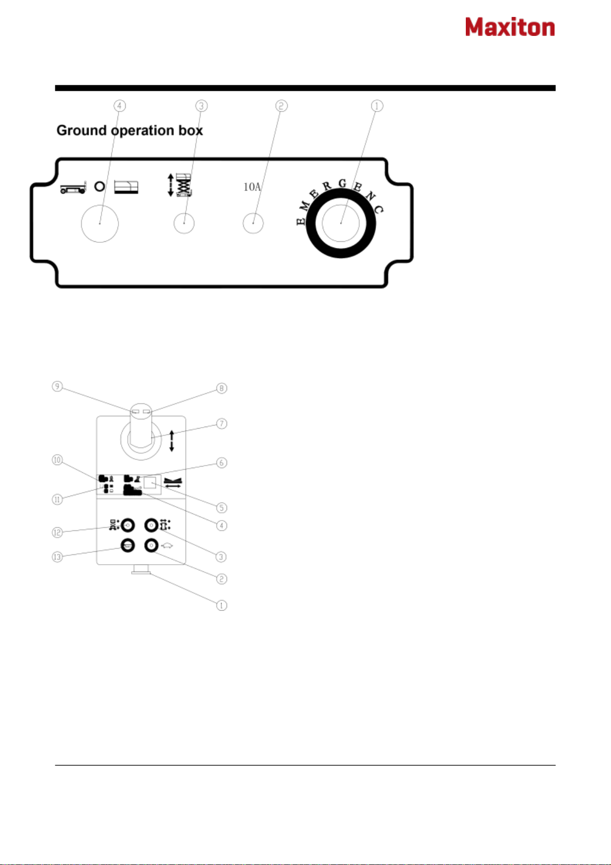
8.The ground operation panel
9.Power unit box
10.Fixed the brake wheel
11.Entrance to the stairs
12.Scissor stack
Operation and Maintenance Manual Second Edition A Brand of Niuli
9 MAXITON GTJZ
1.Emergency stop button 2.10A insurance
3.lifting switch 4. Change switch
Platform control box
1.Emergency stop button
2.Fast and low speed conversion
3.Switch to walk
4.Refer to manuals
5.Display screen
6.Tilt instructions marked
7.Manipulation of the handle
8.Turn Right switch
9.Turn left to the switch
10.Overweight instructions marked
11.Power indicator label
12.Lifting switch
13.The horn switch

Operation and Maintenance Manual Second Edition
10 Maxiton GTJZ
Pre-operation Inspection
You learn and practice the principles of safe
machine operation contained in this operator's manual.
1 Avoid hazardous situations.
2 Always perform a pre-operation inspection.
Know and understand the pre-operation
inspection before going on to the next section.
3 Always perform function tests prior to use.
4 Inspect the workplace.
5 Only use the machine as it was intended.
Fundamentals
It is the responsibility of the operator to perform a pre-
operation inspection and routine maintenance.
The pre-operation inspection is a visual inspection
performed by the operator prior to each work shift.
The inspection is designed to discover if anything is
apparently wrong with a machine before the operator
performs the function tests.
The pre-operation inspection also serves to determine
if routine maintenance procedures are required. Only
routine maintenance items specified in this manual may
be performed by the operator.
Refer to the list on the next page and check each of the
items and locations for modifications, damage or loose
or missing parts.
A damaged or modified machine must never be used. If
damage or any variation from factory delivered
condition is discovered, the machine must be tagged
and removed from service.
Repairs to the machine may only be made bya qualified
service technician, according to the manufacturer's
specifications. After repairs are completed, the operator
must perform a pre-operation inspection again before
going on to the function tests.
Scheduled maintenance inspections shall be
performed by qualified service technicians, according
to the manufacturer's specifications and the
requirements listed in the responsibilities manual.
Pre-operation Inspection
Be sure that the operator's, safety and responsibilities
manuals are complete, legible and in the storage
container located on the platform.
Be sure that all decals are legible and in place.See
Decals section.
Check for hydraulic oil leaks and proper oil level.Add oil
if needed. See Maintenance section.
Check for battery fluid leaks and proper fluidlevel. Add
distilled water if needed. See Maintenance section.
Check the following components or areas for damage,
modifications and improperly installed or missing parts:
Electrical components, wiring and electrical
cables
Hydraulic power unit, tank, hoses, fittings,
cylinders and manifolds
Battery pack and connections
Drive motors
Wear pads
Tires and wheels
Limit switches, alarms and horn
Nuts, bolts and other fasteners
Platform entry chain (if equipped)
Platform entry gate (if equipped)
Beacon and alarms (if equipped)
Brake release components
Safety arm
Pothole guards
Platform extension
Scissor pins and retaining fasteners
Do Not Operate Unless:
Operation and Maintenance Manual Second Edition
11 Maxiton GTJZ
Platform control joystick
Generator (if equipped)
Counterweight (if equipped)
Check entire machine for:
Cracks in welds or structural components
Dents or damage to machine
Be sure that all structural and other critical
components are present and all associated fasteners
and pins are in place and properly tightened.
Side rails are installed and bolts are fastened
Be sure that the chassis trays are in
place,latched and properly connected.
Maintenance
Observe and Obey:
Only routine maintenance items
specified in this manual shall be
performed by the operator.
Scheduled maintenance inspections shall be
completed by qualified service technicians, according
to the manufacturer's specifications and the
requirements specified in the responsibilities manual.
Maintenance Symbols Legend
The following symbols have been
used in this manual to help communicate the intent of
the instructions. When one or more of the symbols
appear at the beginning of a maintenance procedure,
it conveys the meaning below.
Indicates that tools will be required to perform this
procedure.
Indicates that new parts will be required to perform this
procedure.
Indicates that tools will be required to
perform this procedure.
Indicates that new parts will be required to
perform this procedure.
Check the Hydraulic Oil Level
Maintaining the hydraulic oil at the proper
levels is essential to machine operation.
Improper hydraulic oil levels can damage
hydraulic components. Daily checks allow the inspector
to identify changes in oil level that might indicate the
presence of hydraulic system problems.
Perform this procedure with the platform
in the stowed position.
1 Visually inspect the oil level in the hydraulic tank
through the sight gauge in the side of the power unit
module.
Result: The hydraulic oil level should be within the full
and add marks on the oil level indicator decal.
2 Add oil if necessary. Do not overfill.
Hydraulic oil specifications
Hydraulic oil type: L—HV46
Check the Batteries
Proper battery condition is essential to
good engine performance and operational
safety. Improper fluid levels or damaged
cables and connections can result in engine
component damage and
hazardous conditions.
This procedure does not need to be
performed on machines with sealed or maintenance-
free batteries.
Electrocution hazard. Contact with
hot or live circuits may result in death or serious injury.
Remove all rings, watches and other jewelry.
Bodily injury hazard. Batteries contain acid. Avoid
spilling or contacting battery acid. Neutralize battery
acid spills with baking soda and water.

Operation and Maintenance Manual Second Edition
12 Maxiton GTJZ
Perform this test after fully
charging the batteries.
1 Put on protective clothing and eye wear.
2 Be sure that the battery cable connections aretight
and free of corrosion.
3 Be sure that the battery retaining fasteners are in
place and secure.
4 Remove the battery vent caps.
5 Check the battery acid level of each battery. If
needed, replenish with distilled water to the bottom of
the battery fill tube. Do not overfill.
6 Install the vent caps.
Scheduled Maintenance
Maintenance performed quarterly, annually and every
two years must be completed by a person trained and
qualified to perform maintenance on this machine
according to the procedures found in the service
manual for this machine.
Machines that have been out of service for more than
three months must receive the quarterly inspection
before they are put back into service.
After repairs are completed, the operator must perform
a pre-operation inspection and function tests again
before putting the machine into service.
1 Select a test area that is firm, level and free of
obstruction.
2 Be sure the battery pack is connected.
At the Ground Controls
i. Pull out the platform and ground red Emergency Stop
buttons to the on position.
ii. Turn the key switch to ground control.
Test Emergency Stop
6 Push in the ground red Emergency Stop
button to the off position.
Result: No functions should operate.
7 Pull out the red Emergency Stop button to
the on position.
Test the Up/Down Functions
The audible warnings on this machine and the standard
horn all come from the same central alarm. The horn is
a constant tone. The descent alarm sounds at 60 beeps
per minute.And the descent alarm sounds at 120 beeps
per minute when the platform bellow 3.5m
8 Activate the up function.
Result: The platform should raise.
9 Activate the down function.
Result: The platform should lower. The descent alarm
should sound while the platform is lowering.
Test Auxiliary Lowering/Manual Lowering
10 Activate the up function and raise the platform
approximately 2 feet / 60 cm.
You learn and practice the principles of safe machine
operation contained in this operator's manual.
1 Avoid hazardous situations.
2 Always perform a pre-operation inspection.
3 Always perform function tests prior to use. Know
and understand the function tests before going on to
the next section.
4 Inspect the workplace.
5 Only use the machine as it was intended.
Fundamentals
The function tests are designed to discover any
malfunctions before the machine is put into service. The
operator must follow the step-by-step instructions to
test all machine functions.
A malfunctioning machine must never be used. If
malfunctions are discovered, the machine must be
tagged and removed from service. Repairs to the
machine may only be made by a qualified service
technician, according to the manufacturer's
specifications.
11 Activate the auxiliary lowering/manual lowering
function. Move the toggle switch OR pull the knob
OR push the button.
Result: The platform should lower. The descent alarm
will not sound.
Function Tests
Do Not Operate Unless:

Operation and Maintenance Manual Second Edition
13 Maxiton GTJZ
12 Turn the key switch to platform control.
At the Platform Controls
Test Emergency Stop
13 Push in the platform red Emergency Stop buttonto
the off position. Result: No functions should operate.
Test the Horn
14 Pull the red Emergency Stop button out to the on
position.
15 Push the horn button.
Result: The horn should sound.
Test the Function Enable Switch
16 Do not hold the function enable switch.
17 Slowly move the control handle in the direction
indicated by the yellow arrow, then in the direction
indicated by the red arrow. Result: No functions
should operate.
Test the Up/Down Functions
18 Press the lift function select button.
Press and hold the lift function enable button. Move
the lift/drive selector switch to the lift position (if
equipped).
19 Press and hold the function enable switch on the
control handle.
20 Slowly move the control handle in the direction
indicated by the blue arrow.
Result: The platform should raise. The pothole guards
should deploy.
21 Release the control handle.
Result: The platform should stop raising.
22 Press and hold the function enable switch. Slowly
move the control handle in the direction indicated by
the yellow arrow.
Result: The platform should lower. The descent alarm
should sound while the platform is lowering.
Test the Steering
Note: When performing the steer and drive function
tests, stand in the platform facing the steer end of the
machine.
23 Press the drive function select switch. Move
the lift/drive selector switch to the drive position (if
equipped).
24 Press and hold the function enable switch on
the control handle.
25 Depress the thumb rocker switch on top of the
control handle in the direction identified by the yellow
triangle on the control panel. Result: The steer wheels
should turn in the direction that the yellow triangle points
on the control panel.
26 Depress the thumb rocker switch in the
direction identified by the red triangle on the control
panel. Result: The steer wheels should turn in the
direction that the yellow triangle points on the control
panel.
Test Drive and Braking
27 Press and hold the function enable switch on
the control handle.
28 Slowly move the control handle in the direction
indicated by the yellow arrow on the control panel until
the machine begins to move, then return the handle to
the center position.
Result: The machine should move in the direction
that the yellow arrow points on the control panel,
then come to an abrupt stop.
29 Slowly move the control handle in the direction
indicated by the red arrow on the control panel until the
machine begins to move, then return the handle to the
center position.
Result: The machine should move in the direction that
the red arrow points on the control panel, then come to
an abrupt stop. Note: The brakes must be able to hold
the machine on any slope it is able to climb.
Test Limited Drive Speed
30 Press the lift function select button.
Press and hold the lift function enable button.
Move the lift/drive selector switch to the
lift position (if equipped).
31 Press and hold the function enable switch on the
control handle. Raise the platform
approximately 3.5 m from the ground. Result:
The pothole guards should deploy.
32 Press the drive function select switch. Move the
lift/drive selector switch to the drive position (if
equipped).
33 Press and hold the function enable switch on the
control handle. Slowly move the control handle to
the full drive position.
Result: The maximum achievable drive speed with the
platform raised should not exceed 0.8km/h per second.

Operation and Maintenance Manual Second Edition
14 Maxiton GTJZ
If the drive speed with the platform raised exceeds
0.8km/h, immediately tag and remove the machine from
service.
Test the Tilt Sensor Operation
Note: Perform this test from the ground with the
platform controller. Do not stand in the platform.
34 Fully lower the platform.
35 Place a 2x4 or similar piece of wood under both
wheels on one side and drive the machine up onto
them.
36 Raise the platform approximately 3.5 m from the
ground.
37 Lower the platform and remove both pieces of
wood.
Test the Pothole Guards
Note: The pothole guards should automatically deploy
when the platform is raised. The pothole guards activate
two limit switches which control the machine drive
speed. If the pothole guards do not deploy and the
platform is raised above 3.5 m, an alarm sounds and
the machine will not drive.
38Raise the platform.
Result: When the platform is raised 3.5 m from the
ground, the pothole guards should deploy.
39 Press on the pothole guards on one side, and then
the other.
Result: The pothole guards should not move.
40 Lower the platform.
Result: The pothole guards should return to the stowed
position.
41 Place a 2x4 or similar piece of wood under a
pothole guard. Raise the platform.
Result: Before the platform is raised 3.5 m from the
ground, an alarm should sound and the drive function
should not work.
42 Lower the platform and remove the 2x4.
Workplace Place Inspection
You learn and practice the principles of safe machine
operation contained in this operator's manual.
1 Avoid hazardous situations.
2 Always perform a pre-operation inspection.
3 Always perform function tests prior to use.
4 Inspect the workplace.
Know and understand the workplace inspection
before going on to the next section.
5 Only use the machine as it was intended.
Fundamentals
The workplace inspection helps the operator determine
if the workplace is suitable for safe machine operation.
It should be performed by the operator prior to moving
the machine to the workplace.
It is the operator's responsibility to read and remember
the workplace hazards, then watch for and avoid
them while moving, setting up and operating the
machine.
Workplace Inspection
Be aware of and avoid the following hazardous
situations:
drop-offs or hole
bumps, floor obstructions or debris
overhead obstructions and high voltage
conductors hazardous
location
inadequate surface support to withstand all load
forces imposed by the machine wind and
weather condition the presence of
unauthorized personnel other possible
unsafe condition
Operating Instructions
Do Not Operate Unless:
Do Not Operate Unless:

Operation and Maintenance Manual Second Edition
15 Maxiton GTJZ
You learn and practice the principles of safe machine
operation contained in this operator's manual.
1 Avoid hazardous situations.
2 Always perform a pre-operation inspection.
3 Always perform function tests prior to use. 4
Inspect the workplace.
5 Only use the machine as it was intended.
Fundamentals
The Operating Instructions section provides instructions
for each aspect of machine operation.It is the operator's
responsibility to follow all the safety rules and
instructions in the operator's, safety and responsibilities
manuals.
Using the machine for anything other than lifting
personnel and tools to an aerial work site is unsafe and
dangerous.
Only trained and authorized personnel should be
permitted to operate a machine. If more than one
operator is expected to use a machine at different times
in the same work shift, they must all be qualified
operators and are all expected to follow all safety rules
and instructions in the operator's, safety and
responsibilities manuals. That means every new
operator should perform a pre-operation inspection,
function tests, and a workplace inspection before using
the machine.
Emergency Stop
Push in the red Emergency Stop button to the off
position at the ground controls or the platform controls
to stop all functions.
Repair any function that operates when either red
Emergency Stop button is pushed in.
Auxiliary Lowering/Manual Lowering
1 Activate the auxiliary lowering/manual lowering
function. Move the toggle switch OR pull the knob OR
push the button.
Operation From Ground
1 Turn the key switch to ground control.
2 Pull out both ground and platform red Emergency
Stop buttons to the on position.
3 Be sure the battery pack is connected before
operating the machine.
To Position Platform
1 Move the up/down toggle switch according to the
markings on the control panel.
Drive and steer functions are not available from the
ground controls.
Operation From Platform
1 Turn the key switch to platform control.
2 Pull out the ground and platform red Emergency Stop
buttons to the on position.
3 Be sure the battery pack is connected before
operating the machine.
To Position Platform
1 Press the lift function select button.
Press and hold the lift function enable button.
Move the lift/drive selector switch to the
lift position (if equipped).
2 Press and hold the function enable switch on the
control handle.
3 Move the control handle according to the markings
on the control panel.
CE models: When lowering the platform, the platform
should stop when it is 7 feet / 2.1 m from the ground. Be
sure the area below the platform is clear of personnel
and obstructions before continuing. To continue
lowering, release the control handle, wait 5 seconds,
then move the control handle again.
To Steer
1 Press the drive function select button.
Move the lift/drive selector switch to the
drive position.
2 Press and hold the function enable switch on the
control handle.
3 Turn the steer wheels with the thumb rocker
switch located on the top of the control handle.
To Drive
1 Press the drive function select button.
Move the lift/drive selector switch to the drive
position.
2 Press and hold the function enable switch on the
control handle.
3 Increase speed: Slowly move the control handle off
center.
Decrease speed: Slowly move the control handle
toward center.
Stop: Return the control handle to center or
release the function enable switch.

Operation and Maintenance Manual Second Edition
16 Maxiton GTJZ
Use the color-coded direction arrows on the platform
controls and on the platform to identify the direction the
machine will travel.
Machine travel speed is restricted when the platform
is raised.
Battery condition will affect machine performance.
Machine drive speed and function speed will drop when
the low battery indicator light is on or when the last light
on the battery level indicator is flashing.
Error Indicator Light On
If the error indicator light is on,push in and pull out the
red Emergency Stop button to reset the system.
If the light stays on, tag and remove the machine from
service.
Drive Select Switch
Machine on incline symbol: Low range operation for
inclines
Move the toggle switch down for normal drive
operation.
To Extend and Retract Platform
1 Step on the platform extension release pedal
on the platform toe-board.
2 Grasp the platform guard rails and carefully
push to extend the platform to the mid-position stop.
3 Step on the release pedal again and push to
fully extend the platform.
Do not stand on the platform extension while trying to
extend it.
4 Step on the platform extension release pedal
and pull to retract the platform to the mid- position stop.
Step again to fully retract the platform.
Models without chassis counterweight: The platform
extension limit switch will disable the drive function
when the platform is extended and the platform is raised
above
26 ft / 7.9 m. Lower the platform or retract the platform
extension to drive the machine.
Operation From Ground with Controller
Maintain safe distances between the operator, machine
and fixed objects.
Be aware of the direction the machine will travel when
using the controller.
After Each Use
1 Select a safe parking location!afirm leve surface,
clear of obstruction and traffic.
2 Lower the platform.
3 Turn the key switch to the off position and remove
the key to secure from unauthorized use.
4 Chock the wheels.
5 Charge the batteries.
Battery and Charger Instructions
Observe and Obey:
Do not use an external charger or booster battery.
Charge the battery in a well-ventilated area.
Use proper AC input voltage for charging as indicated
on the charger.
Use only Niuli authorized battery and charger.
To Charge Battery
1 Be sure the batteries are connected before charging
the batteries.
2 Open the battery compartment. The compartment
should remain open for the entire charging cycle.
3 Remove the battery vent caps and check the battery
acid level. If necessary, add only enough distilled
water to cover the plates. Do not overfill prior to the
charge cycle.
4 Replace the battery vent caps.
5 Connect the battery charger to a grounded AC
circuit.
6 Turn the battery charger on.
7 The charger will indicate when the battery is fully
charged.

Operation and Maintenance Manual Second Edition
17 Maxiton GTJZ
8 Check the battery acid level when the charging cycle
is complete. Replenish with distilled water to the
bottom of the fill tube. Do not overfill.
Dry Battery Filling and Charging
Instructions
1 Remove the battery vent caps and permanently
remove the plastic seal from the battery vent
openings.
2 Fill each cell with battery acid (electrolyte) until the
level is sufficient to cover the plates.
Do not fill to maximum level until the battery charge
cycle is complete. Overfilling can cause the battery acid
to overflow during charging. Neutralize battery acid
spills with baking soda and water.
3 Install the battery vent caps.
4 Charge the battery.
5 Check the battery acid level when the charging cycle
is complete. Replenish with distilled water to the
bottom of the fill tube. Do not overfill.
Transport Instructions
Observe and Obey:
Common sense and planning must be applied to control
the movement of the machine when lifting it with a crane
or forklift.
The transport vehicle must be parked on a level
surface.
The transport vehicle must be secured to prevent
rolling while the machine is being loaded.
Be sure the vehicle capacity, loading surfaces and
chains or straps are sufficient to withstand the machine
weight. See the serial plate for the machine weight.
The machine must be on a level surface or secured
before releasing the brakes.
Securing to Truck or Trailer for Transit
Always chock the machine wheels in preparation for
transport.
Use the tie-down points on the chassis for anchoring
down to the transport surface.
Use chains or straps of ample load capacity.
Turn the key switch to the off position and remove the
key before transporting.
Inspect the entire machine for loose or unsecured
items.
Brake Release Operation
1 Chock the wheels to prevent the machine from
rolling.
2 Be sure the winch line is properly secured to the
drive chassis tie points and the path is clear of all
obstructions.
3 Turn the brake release knob counterclockwise to
open the brake valve.
4 Pump the brake release pump knob.
After the machine is loaded:
1 Chock the wheels to prevent the machine from
rolling.
2 Turn the brake release knob clockwise to reset
the brakes.
Repair Procedures
Observe and Obey:
➢Repair procedures shall be completed by a
person trained and qualified on the repair of this
machine.
➢Immediately tag and remove from service a
damaged or malfunctioning machine. Repair any
Operation and Maintenance Manual Second Edition
18 Maxiton GTJZ
machine damage or malfunction before operating the
machine.
Before Repairs Start:
➢Read, understand and obey the safety rules
and operating instructions in the GTJZ06/08/10 /12/14
Operator’s Manual.
➢Be sure that all necessary tools and parts are
available and ready for use.
➢Read each procedure completely and adhere
to the instructions. Attempting shortcuts may produce
hazardous conditions. Unless otherwise specified,
perform each repair procedure with the machine in the
following configuration:
· Machine parked on a flat, level surface
· Boom in the stowed position
· Turntable rotated with the boom between the circle-
end wheels
· Turntable secured with the turntable rotation lock
pin · Key switch in the OFF position with the key
removed
· Welder disconnected from the machine
· Wheels chocked
Repair Procedures
Most of the procedures in this section should
only be performed by a trained service
professional in a suitably equipped workshop.
Select the
appropriate repair procedure after troubleshooting
the problem.
Perform the disassembly procedures to the point
where repairs can be completed. Then to re-
assemble, perform the disassembly steps in reverse
order.
Symbols Legend
Safety alert symbol!used to alert personnel to
potential personal injury hazards. Obey all safety
messages that follow this symbol to avoid possible
injury or death.
Red! Used to indicate the
presence of an imminently hazardous situation
which,if not avoided, will result in death or serious
injury.
Orange! used to indicate the
presence of a potentially hazardous situation which,if
not avoided, could result in death or serious injury.
Yellow with safety alert symbol!
used to indicate the presence of a potentially
hazardous situation which, if not avoided, may cause
minor or moderate injury.
Yellow without safety alert symbol! used to indicate
the presence of a potentially hazardous situation
which, if not avoided, may result in property damage.
Green! used to indicate
operation or maintenance information.
Platform Components 1-1 Platform
How to Remove the Platform
1 Find the link to the ministry of tank
bottom,control cables.Recognize that the number of
the cable and position.
2 From the control of the tank bottom off cable.
3 Remove the bolt platform control box.Move machine
control box and kaiping aside. 4 Remove platform base
and arm the axid of a connection,and remove the
slider.
5 Remove the whole work platform.
Operation and Maintenance Manual Second Edition
19 Maxiton GTJZ
Electrocution hazard. Contact
with electrically charged circuits could result in death or
serious injury. Remove all rings, watches and other
jewelry.
1-2 Extensions
platform
1 On the platform level
2 Remove the shaft on both sides in the roller,remove
the roller.
3 Removed extensions platform.
1-3
Platform Guardrail
1 On the platform level
2 Remove the guardrail and respectively chassis
connected pin shaft,put up good.
3 In turn off the fence respectively
Boom Components 2-1
How to Remove the Boom
When remove hose and tube fittings,must remove hose
or at the end of the pipe joints of the O-rings.
In the arm in position when the
plane contract execution of the process.
1 Remove after work platform
2 Remove arm wearing and the axis of joint
chassis,remove the slider.
3 Remove and lifting cylinder pipe and connect the
join,move the pipe joints,and all the wires.
4 Arms frame in the whole discharge level
5 Dismantling the lifting oil cylinder,then moved away
6 From up to down in each arm between frame
removed connecting shaft,according to the order put
them in order.
7 Remove the arm of the frame on the last shock the
slider.
Chassis parts 3-1 Drive Pump
Drive pump is a long working power unit.The output of
the pump by the pump the points on the displacement
control.
How to Remove the Drive Pumps
1 Disconnect the electric drive pump in the
displacement controller circuit connection.
2 Shut down two at hydraulic oil tank on the hydraulic
oil tank globe valve.
3 From the drive pump mark, disconnect and fort
hydraulic hose.
4 With proper support equipment support drive pump
and remove two drive pump installation bolt.
5 Be careful to pull out until the pump shaft drive pump
spline from flexible coupling.
6 Move up the drive pump from the machine.
3-2 Hydraulic oil tank
How to Remove the Hydraulic oil
tank
1 Open at the side of the hydraulic oil tank
This manual suits for next models
5
Table of contents
Popular Scissor Lift manuals by other brands


RUDETRANS
RUDETRANS RLS-G Series USER, OPERATING & INSTALLATION MANUAL

Terex
Terex Genie GS-2668 RT Operator's manual

DINGLI
DINGLI SP039-E operators manual with maintenance information

LINCOS
LINCOS STD-5335A Use and maintenance manual

twin busch
twin busch TW S3-18U Installation, operation, and parts manual

Hy-Brid Lifts
Hy-Brid Lifts SERIES II Operation & safety manual

Custom Equipment
Custom Equipment HB-P830 Addendum manual

EASTMAN
EASTMAN ES1932 Operation & safety manual

JLG
JLG 260MRT Service and maintenance manual

Presto Lifts
Presto Lifts ECOA PDL60-50 owner's manual

DINGLI
DINGLI JCPT0808 operators manual with maintenance information

Hy-Brid Lifts
Hy-Brid Lifts 1 Seris Operation & safety manual