NJD Electronics IF32 User manual
IF3 2
User Guide


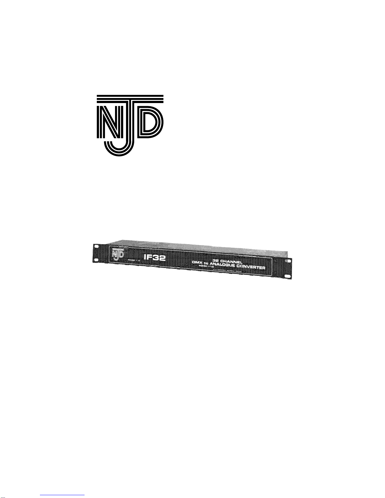
Features
T h e IF 3 2 e n a b le s t h e c o n ve r s io n o f a s t a n d a r d
D M X s ig n a l t o t w o s e t s o f 1 6 a n a lo g u e o u t p u t s o f
0 › 1 0 V. P o w e r e d fr o m a n y N J D p o w e r p a c k, t h e
IF 3 2 r e q u ir e s n o m a in s p o w e r s u p p ly a n d w ill a llo w
e a c h s e t o f 1 6 o u t p u t s t o b e a s s ig n e d t o a n y 1 6
c o n s e c u t ive D M X a d d r e s s e s . S u p p lie d in a 1 U r a c k
m o u n t c a s e w it h a ll e x t e r n a l c o n n e c t io n s t h e IF 3 2
fe a t u r e s IN a n d O U T D M X s o c k e t s a llo w in g it t o b e
in t r o d u c e d a t a n y p o in t in t h e D M X s ig n a l s u p p ly
lin e . Installat ion.
Connect the incoming DMX signal to the ¼” jack socket
marked DMXin. Continue the DMX chain from the ¼” jack socket
marked DMXout to the next item in the DMX control chain.
The IF32 will operate with either switching of dimming power
packs (such as the DP5000, DP10000 and SP10000) provided
that they have a +15V output.
To Connect to an NJ D rack›mount ed
power pack (DP1 0 0 0 0 x or SP1 0 0 0 0 x)
Use a 7-pin DIN-DIN straight wired lead i.e. pin 1 - pin 1, pin
2 - pin 2, pin 3 - pin 3 etc. Connect from the output of the IF32 to
the input of the power pack. Ensure that the +10V terminal inside
the power pack is linked to the ENABLE terminal.
To connect t o an NJ D wall mount ed
power pack (DP1 0 0 0 0 or SP1 0 0 0 0 )
Connect a lead from the 7-pin DIN socket output of the IF32
to the ANALOGUE INPUTS terminal block of the power pack.
© N.J.D. Electronics 1997 -Page 3-
IF32 User Guide

Connections are as follows
7-pin DIN socket Terminal block
Pin 1 Channel 1
Pin 2 0V
Pin 3 Channel 4
Pin 4 Channel 2
Pin 5 Channel 3
Pin 6 +15V supply
Pin 7 +15V supply
Link between +10V and ENABLE
Connecting to ot her manufacturers’
power packs
Do not connect to a power packs with a supply voltage
output of more than +20V, nor power packs with a negative
supply voltage output. This may damage the IF32.
Connect the power supply voltage output from the slave pack
to either pin 6 or pin 7 or both on the IF32 7-pin DIN sockets.
Whilst it is only necessary to connect the power supply from
one power pack to each half of the IF32, it is advisable to
connect them all. This ensures that if the mains to one slave pack
is disconnected, then the IF32 does not lose its power supply.
The power supply connections can come from power packs on
different mains phases. The green LEDs will light when power is
present.
If no supply is available from the power pack proceed as
follows:
The IF32 may be used with an external +15V 100mA supply -
connect between pin 6 and pin 2 on two 7-pin DIN sockets, pin 6
positive, pin 2 negative. It is not necessary to use a regulated
supply. Connect to one socket on each half of the IF32.
The IF32 may also be used with a transformer. Use a 12-0-
12V 100mA transformer . Connect as follows: 12V - pin 6 0V - pin
2 12V - pin 7 on two DIN sockets, one DIN socket on each half of
the IF32.
© N.J.D. Electronics 1997 -Page 4-
IF32 User Guide

If only half of the IF32 is being used, it is not necessary to
connect a power supply to the other half. Only one power
indicator will light in this case.
Connect the 0-10V analogue outputs from the IF32 to the
analogue inputs of the power pack.
Sett ing the DMX address switches:
DMX addresses Switches on
(other switches off)
1 to 16 None
9 to 24 8
17 to 32 16
25 to 40 16, 8
33 to 48 32
41 to 56 32, 8
49 to 64 32, 16
57 to 72 32, 16, 8
65 to 80 64
73 to 88 64, 8
81 to 96 64, 16
89 to 104 64, 16, 8
97 to 112 64, 32
105 to 120 64, 32, 8
113 to 127 64, 32, 16
121 to 136 64, 32, 16, 8
129 to 144 128
137 to 152 128, 8
145 to 160 128, 16
153 to 168 128, 16, 8
161 to 176 128, 32
169 to 184 128, 32, 8
177 to 192 128, 32, 16
© N.J.D. Electronics 1997 -Page 5-
IF32 User Guide

185 to 200 128, 32, 16, 8
193 to 208 128, 64
201 to 216 128, 64, 8
209 to 224 128, 64, 16
217 to 232 128, 64, 16, 8
225 to 240 128, 64, 32
233 to 248 128, 64, 32, 8
241 to 256 128, 64, 32, 16
Do not set all switches ON
The DMX address for each half of te IF32 can be set
independently.
The 0 to 10 Volt analogue control signals corresponding to
the DMX channels selected appear on the 7-pin DIN sockets.
The lowest numbered DMX address appears on IF32 output
channel 1, and the highest on IF32 output channel 16.
For example: If switches are set with Switch 128 and 8 on
and others off. This selects DMX addresses 137 to 152. DMX
address 137 will control channel 1, 138 will control channel 2,
139 will control channel 3, and so on, up to DMX address 152
which will control channel 16 on the IF32.
The IF32 cannot be used with DMX addresses above 256.
Cont rolling power packs from an
intelligent DMX controller such as Merlin.
For a dimming power pack
Output brightness is proportional to DMX data:
DMX data = 255 output fully on
DMX data = 128 output at half brightness
DMX data = 64 output at quarter brightness
DMX data = 0 output fully off (if preheat is disabled)
These are only examples, the IF32 and a dimming power
pack can produce all 256 levels of brightness from fully off to fully
on.
© N.J.D. Electronics 1997 -Page 6-
IF32 User Guide

For a switching power pack:
DMX data < 76 output definitely off
DMX data > 180 output definitely on
DMX data between 76 and 180: do not use -
output may be on or off.
DMX.
The DMX system is a high-speed digital data system, which
can transmit all the information required for light dimmers, multi-
motor lighting effects etc. down a single cable.
There is no limit to the number of units that can be connected
to the DMX signal, but it is not recommended that the total cable
length should exceed 250m.
Each unit connected to the DMX signal is given an address,
and it compares this to the data being sent on the DMX cable, so
it can determine which data is addressed to it. It then uses this
data to move a motor or set a brightness level as required by the
controller.
As the DMX system can transmit as much information as 512
analogue control wires down a single cable, it has to transmit
very quickly, in fact, at a frequency 12 times higher than the
highest audio frequency. Anyone who has used long leads for
audio will realise that it is difficult to do without losing the higher
frequencies. To make the DMX system work at such high
frequencies, it requires special circuitry and special cable.
Cable can be designed to pass high frequencies with no loss
if it has the correct resistance connected at each end, this
resistance is called the characteristic
impedance of the cable. DMX cable has
a characteristic impedance of 120W.
All NJD DMX products are designed to ensure that the
resistors are connected automatically. Without them, the signal
reflects off the end of the cable and interferes with the new data
coming the other way. If the cable is not correct, the system will
not work. Most good quality low-capacitance screened twisted
pair cables will work, but twin individually screened will not. Also,
© N.J.D. Electronics 1997 -Page 7-
IF32 User Guide

if the cable is split or joined other than end-to end, the system will
stop working. Fault Finding
Channel 2 flashes on and off and other outputs go to full
brightness.
No valid DMX signal
No output
Power pack does not produce a +15V output
DIL switches set to wrong address.
Voltage is measured on IF32 output but power pack
outputs do not operate.
ENABLE and +10V are not linked in the power pack.
© N.J.D. Electronics 1997 -Page 8-
IF32 User Guide

Technical Specificat ion.
Dimensions: 482 × 110 × 44mm
Power requirements: +15V DC @ 100mA
Minimum: +12V DC
Maximum: +20V DC
Input: DMX512
DMX Connectors: ¼” stereo jack
tip = data+
ring = data-
sleeve = earth
Output: 0 to +10V analogue
Output current: 20mA maximum
Output connectors: 7-pin DIN sockets
7-Pin DIN socket connections:
Pin 1: Channel 1 Channel 5 Channel 9 Channel 13
Pin 2: 0V 0V 0V 0V
Pin 3: Channel 4 Channel 8 Channel 12 Channel 16
Pin 4: Channel 2 Channel 6 Channel 10 Channel 14
Pin 5: Channel 3 Channel 7 Channel 11 Channel 15
Pin 6: +15V input +15V input +15V input +15V input
Pin 7: +15V input +15V input +15V input +15V input
© N.J.D. Electronics 1997 -Page 9-
IF32 User Guide

© N.J.D. Electronics 1997 -Page 10-
IF32 User Guide


© Copyright N.J.D. electronics. Neither the whole nor any
part of the information contained in, nor the product described in
this User Guide may be adapted, copied, or reproduced in any
form except with the prior written approval of N.J.D. Electronics.
All correspondence should be addressed to:
Customer Support,
N.J.D. Electronics,
10-11, Ascot Industrial Estate,
Sandiacre,
Nottingham,
England.
NG10 5DJ.
Telephone: +44 (0) 115 939 4122
Facsimile: +44 (0) 115 949 0453
Technical Help line: +44 (0) 115 949 0038
E-mail: [email protected]
URL: http://www.njd.co.uk
Popular Media Converter manuals by other brands

Transition Networks
Transition Networks M/E-TX-FX Series user guide

Converters.TV
Converters.TV 928 Operation manual

IMC Networks
IMC Networks MediaConverter/1 Specifications

Sunricher
Sunricher SR-2103FA quick start guide

Telestream
Telestream lightspeed live capture user guide

Monacor
Monacor DADC-144DT instruction manual


