NL Acoustics LF10 User manual
1
USER MANUAL
LF10

2
NL ACOUSTICS LTD
Hiomotie 3
00380 Helsinki
Finland
+358 (0)10 583 3240
www.nlacoustics.com
FI-26650896
Document version of: June 1, 2022
This User Manual supports the following LF10 version:
S/N: AC13xxxx SW: 22H1

3
TABLE OF CONTENTS
1. Notice to user 4
1.1 Legal 4
1.2 Compliance 4
1.3 Markings 5
1.4 Customer help 5
1.5 Disposal of electronic waste 5
2. Introduction 6
2.1 User safety 6
2.2 Specifications 7
2.3 Package contents 8
2.4 Camera parts 9
2.5 Battery parts 10
2.5.1 RRC2040 battery parts 10
2.5.2 RRC2040 external battery charger 10
2.5.3 Tracer external battery parts 11
2.5.4 Tracer external battery charger 11
2.6 Spare parts and accessories 11
3. Getting started 12
3.1 Charging 12
3.1.1 Charging the RRC2040 battery 12
3.1.2 Charging the Tracer external battery 13
3.2 Startup 14
3.2.1 Startup with RRC2040 battery 14
3.2.2 Startup with Tracer external battery 15
3.3 Device setup wizard 16
3.3.1 Device registration 16
3.4 Shutdown 16
3.4.1 Shutdown with RRC2040 battery 16
3.4.2 Shutdown with Tracer external battery 16
4. User interface 17
4.1 Heatmap 17
4.2 Taking a snapshot 18
4.3 Recording a video 18
4.4 Snapshot browser 18
4.4.1. Snapshot upload options 18
4.4.2 Tagging snapshots 18
4.5 Zoom 19
4.6 Quick settings 19
4.6.1 Screen brightness 19
4.6.2 Single-source / multi-source mode 19
4.7 Settings 19
4.7.1 Network settings 19
4.7.2 Time settings 20
4.7.3 Advanced settings 20
Language 20
Distance unit of measurement 20
Reset settings 20
Available filters 20
Remove all data 20
Calibration mode 20
4.8 Real-time analysis 20
4.9 Cloud upload 21
4.10 USB export 21
4.11 Direct data transfer 21
4.12 Remote update 22
4.13 USB update 22
5. Air leak detection features 22
5.1 AutoFilter 22
5.2 AutoDistance 23
5.3 Specific settings 23
Leak unit of measurement 23
Currency 23
Energy cost 23
Cost calculation 23
Env. temp. 23
Rel. humidity 23
Leak corr. 23
Specific power 23
Utilization 23
Non-air leak detection 23
6. Usage techniques 24
6.1 General usage 24
6.2 Locating sound sources 24
6.3 Reflections 25
6.4 Capturing distance 25
7. NL Cloud 26
8. NL Camera Viewer and
NL Camera Viewer Pro offline soware 26
9. Maintenance 27
9.1 Storage 27
9.2 Cleaning 27
9.3 Visual and/or permanent damage 27
9.4 Recycling 27

4
1. NOTICE TO USER
1.1 Legal
Contact your distributor for the warranty terms and
conditions.
©2022, NL Acoustics Ltd. All rights reserved
worldwide. Names and marks appearing on the products
noted in this User Manual are either registered trademarks
or trademarks of NL Acoustics and/or its subsidiaries.
All other trademarks, trade names, or company names
referenced herein are used for identification purposes
only and are the property of their respective owners.
As NL Acoustics Ltd is committed to a policy of continuous
development, we reserve the right to make changes and
improvements to any of the products or its documentation
without prior notice.
EXCEPT AS EXPRESSLY PROVIDED IN THIS SECTION
OF THE MANUAL, NL ACOUSTICS LTD PROVIDES
NO WARRANTY, EXPRESS, IMPLIED, STATUTORY OR
OTHERWISE AND SPECIFICALLY DISCLAIMS ANY
WARRANTY OF MERCHANTABILITY OR FITNESS FOR A
PARTICULAR PURPOSE WITH RESPECT TO THE PRODUCT
AND DOCUMENTATION.
1.2 Compliance
We caution the user that changes or modifications not expressly
approved by the party responsible for compliance could void the
user’s authority to operate the equipment.
Note: This equipment has been tested and found to comply with
the limits for a Class A digital device of CISPR 32. It may cause
interference with radio frequency receivers in residential areas, and
it is up to the users themselves to correct the interference. The EMC
conformity of the equipment is indicated by the CE marking which
the equipment bears.
This device complies with part 15 of the FCC Rules. Operation is
subject to the following two conditions:
1: This device may not cause harmful interference, and
2: This device must accept any interference received, including
interference that may cause undesired operation.
Note: This equipment has been tested and found to comply with
the limits for a Class A digital device, pursuant to part 15 of the FCC
Rules. These limits are designed to provide reasonable protection
against harmful interference when the equipment is operated in
a commercial environment. This equipment generates, uses, and
can radiate radio frequency energy and, if not installed and used in
accordance with the instructions, may cause harmful interference to
radio communications. Operation of this equipment in a residential
area is likely to cause harmful interference, in which case the user
will be required to correct the interference at its own expense.
Radio operates in standard 802.11 b/g/n in frequency range 2400-
2480 MHz and 5150-5260 MHz with max. output power 15 dBm.
EU Declaration of Conformity – NL Acoustics LTD declares that the
LF10 complies with the essential requirements and other relevant
provisions of the Radio Equipment Directive (2014/53/EU), Low
Voltage Directive (2014/35/EU), Electromagnetic Compatibility
Directive (2014/30/EU), Restriction of Hazardous Substances
Directive (RoHS, 2011/65/EU) and Regulation concerning the
Registration, Evaluation, Authorisation and Restriction of Chemicals
(REACH, 1907/2006/EU). A copy of the Declaration of Conformity
is available on request.
NOTICE FOR CANADA
This Class A digital apparatus complies with Canadian ICES-003.
Cet appareil numérique de la classe A respecte est conforme à la
norme NMB-003 du Canada.
5
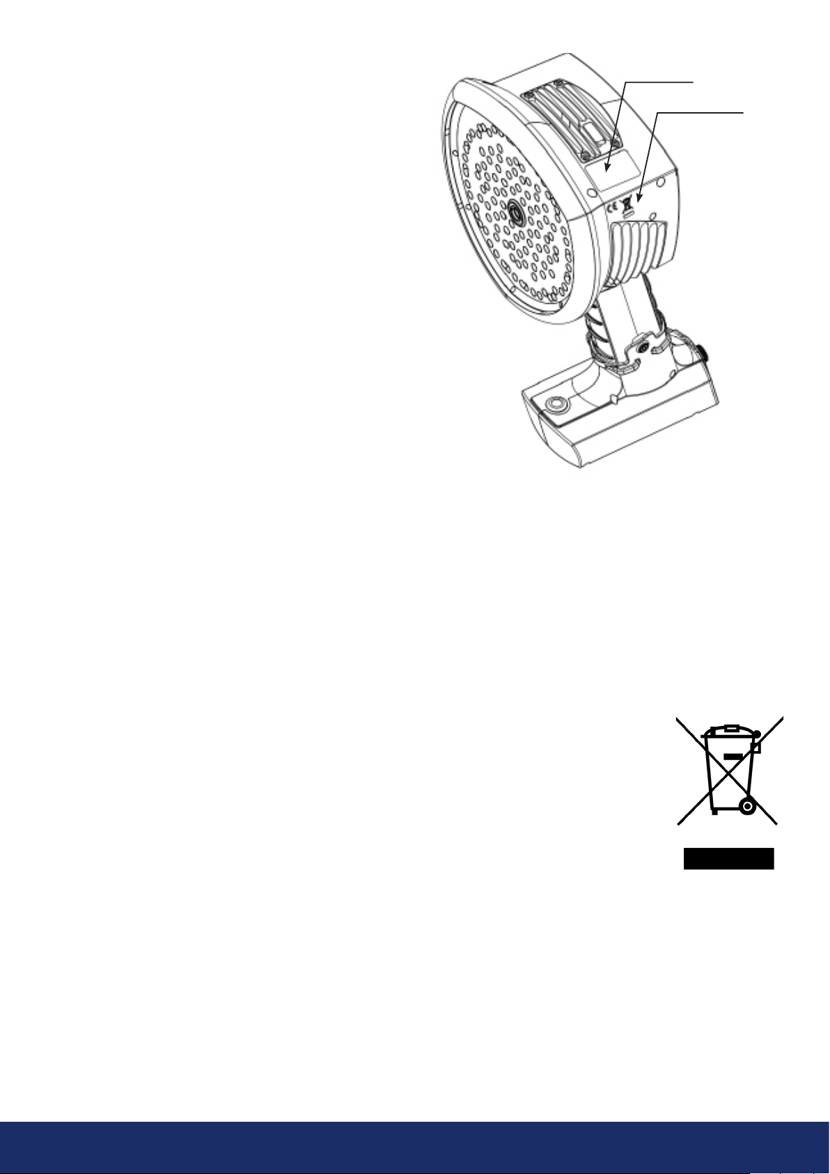
1.3 Markings
The physical device ID label, CE marking, and WEEE
marking are situated on the top le side of the LF10
camera (Image 1).
The ID label contains the following information:
the product name, Canadian ISED certification label,
serial number, Chinese CMIIT ID, country of origin,
company name, and approval markings.
The electronic ID label or e-label containing all the
regulatory information is the primary ID plate of the LF10.
The e-label is available from the LF10 user interface.
Toopen the e-label, press the Settings icon and choose
Device info.
ISED: The certification label of Innovation, Science and
Economic Development Canada (ISED) is a word mark
consisting of the Company Number (CN) and Unique
Product Number (UPN). Serial number: The first four
characters of the serial number are the model number
of the equipment, while the last four characters are the
running identification number:
Serial number
Model number AC13xxxx Device ID
1.4 Customer help
Do not hesitate to contact our Customer Support Center
if you experience problems or have any questions about
your product. Please include the serial number of the
device with your request.
For customer help, go to support.nlacoustics.com.
1.5 Disposal of electronic waste
For users within the European Community
Electrical and electronic equipment (EEE) contains
materials, components, and substances that may be
hazardous and present a risk to human health and the
environment when waste electrical and electronic
equipment (WEEE) is not handled
correctly.
Equipment marked with the
crossed-out wheeled bin (see right) is
electrical and electronic equipment.
The crossed-out wheeled bin symbol
indicates that waste electrical and
electronic equipment should not be
discarded together with unseparated
household waste, rather it must be
collected separately.
For this purpose, all local authorities have established
collection schemes under which residents can dispose
of waste electrical and electronic equipment at a
recycling center or other collection points, or WEEE can
be collected directly from households. More detailed
information is available from the technical administration
of the relevant local authority.
Location of ID label
CE and WEEE markings
Image 1: Label locations on the LF10 camera.

6
2. INTRODUCTION
Thank you for choosing the LF10 camera! The LF10 is a
standalone system for acoustic image measurement and
signal analysis. The 124 microphones of the LF10 are used
to form a precise acoustic image of a specific location.
This acoustic image is superimposed in real-time over
adigital camera image. The location of the sound source
is shown on the camera screen. Sound sources of interest
are separated from background noise. The details of each
acoustic image can be saved onto the NL Cloud for further
viewing and AI-backed analysis.
The LF10 camera is much more sensitive and accurate
than the human ear. The camera can locate sound sources
that are inaudible to the human ear as well as sound
sources that humans cannot reliably locate. The LF10 has
a frequency range that extends to ultrasonic frequencies,
which is a huge advantage since many relevant
problems and phenomena can be precisely located
using ultrasound. One of the core benefits of using the
LF10 camera comes from its ability to hear and analyze
ultrasonic frequencies. Most maintenance and operational
problems can be identified and accurately located at
these frequencies.
2.1 User safety
Only genuine parts from NL Acoustics should be used
with the LF10 camera. Under no circumstances should
users make use of third-party parts.
Do not try to repair or open the enclosure of the LF10
camera or the batteries. Do not use any damaged device,
battery, or cables.
Protect the device and accessories from dirt, dust,
impacts, and liquids. Also protect the camera lens,
themicrophone array, and the USB port from any kind
offoreign objects, dust or liquids.
Charge the battery only when it is disconnected from the
LF10 camera.
The LF10 camera is not intended to be used while the
battery is charging. Charge the battery only when it is
disconnected.
Charge the battery at ambient temperatures between 0°C
and +40°C (32°F and 104°F).
Do not leave the battery unattended during charging.
Do not expose the battery to flame or excessive heat.
Hold the LF10 firmly by the handle and fasten the safety
lanyard to your wrist.
Do not touch the heat sinks when the device is on,
as the heat sinks become hot when the camera is on.
Long-term contact may cause burns. For this reason, it is
recommended that any USB flash drives be connected
directly aer starting the device.
Consult with your safety officer in your facility or working
environment about using the LF10 and, if powering the
device by external battery, about using the carrier bag
with shoulder strap. In you use the shoulder strap with
your LF10, particular care should be taken to prevent
getting entangled in your working environment.
Use only the USB flash drives supplied with the LF10
camera. Using third-party mass storage drives may lead
todata loss or corruption.

7
2.2 Specifications
DEVICE
Manufacturer: NL Acoustics Ltd.
Name: LF10
MECHANICAL AND ENVIRONMENTAL
Size: 315 x 170 x 161 mm (12.4 x 6.7 x 6.3 in)
Weight: 0.980 kg (2.2 lb).
Total weight with RRC2040 battery: 1.2 kg (2.7 lb).
Protection class: IP51
Operation and storage temperature ranges: -10 °C to
+50 °C (14°F to 122°F) / -20°C to +70°C (4°F to 158°F)
Operation and storage humidity range: 0 to 90% RH
Charging ambient temperature range: 0°C to +40°C
(32°F to 104°F)
POWER SUPPLY
Max input rating: 15 VDC, 2.5 A
Internal system backup battery: Li-Ion, 6 Wh
BATTERY OPTIONS
RRC2040 battery: Li-Ion, 10.80 VDC, 3.35 Ah, 36.20
Wh, 0.170 kg (0.37 lb), 85 x 59 x 22 mm (3.34 × 2.31
× 0.86 in), IP40, usage time up to 2.5 h (depending on
conditions), charging time 2 to 3 h.
RRC2040 battery charger: input 19 to 26 VDC, 2.8 A
max, output: 17.4 VDC/4A max, 120 x 64 x 43 mm (4.72
× 2.51 × 1.69 in), 0.110 kg (0.24 lb), operating ambient
temperature range: 0°C to +40°C (32°F to 104°F).
RRC2040 charger power supply: input 100 to 240 VAC
/ 50-60 Hz, output 19 VDC ± 5% / 3.4 A, maximum power
65 W, 95 x 50 x 25.4 mm (3.74 × 1.96 × 1 in), 0.270 kg
(0.59 lb), operating ambient temperature range: 0°C to
+40°C (32°F to 104°F).
Tracer external battery: LiFePO4, 12 VDC, 7 Ah, 84 Wh,
985 g (2.2 lb), 90 x 145 x 65 mm (3.5 × 5.7 × 2.6 in), IP64
protection rating, usage time up to 6 h (depending on
ambient conditions), charging time 4 to 6 h.
Tracer battery cord length: 0.9 m (3.0 ), extended
2 m (6.6 ).
Tracer battery charger: input 100 to 240 VAC ~50/60
Hz, 1.3 to 1.5 A; max. output 13.8 to 14.6VDC, 4.0 A
depending on the charger provided; see the charger
documentation or ID plate.
USER INTERFACE AND DISPLAY
Display: size: 5 in, 800x480; color: 24-bit RGB;
Brightness: 1000 cd/m2 (adjustable)
Input device: resistive touchscreen
Power ON indicator: red LED
Image resolution: 800x480
Video frame rate: 25 fps (max)
Acoustic image frame rate: 30 fps
Directional resolution: 0.5°, max: 0.25°
Field of view (FOV): 62.2° x 48.8°
Zoom: 2x digital zoom
ACOUSTIC SPECIFICATIONS
Acoustic measurement: 124 low-noise MEMS
microphones, real-time sound visualization
Dynamic range, low limit: below -15 dB
Dynamic range, high limit: more than 120 dB
Bandwidth: 2 kHz to 65 kHz (automatic filtering)
Distance: from 0.3 m (1.0 ) up to and above 130 m (430 )
Leak rate: typical industrial environments:
>0.032 l/min @ 3 bar from 3 m (9.8 )
>0.05 l/min @ 3 bar from 10 m (32.8 )
minimum detection: 0.004 l/min @ 1.2 bar from < 1 m (3.0 )
COMMUNICATION AND STORAGE
Wireless data transfer: 2.4 GHz and 5 GHz IEEE
802.11b/g/n/ac secured wireless LAN
Data transfer: USB / direct WiFi transfer / WiFi
Data storage: USB / cloud
Storage, internal: 32 GB SD card, non-removable.
Storage, external: 8 GB USB mass storage device,
included in scope of supply
STANDARDS AND COMPLIANCE
RED: ETSI EN 300 328, ETSI EN 301 893
EMC: ETSI EN 301 489-1/17, EN55032: Class A,
FCC CFR 47, Part 15, Subpart B: Class A,
ICES 003: Class A
RoHS: EN 50581:2012
REACH
Safety: IEC 62368-1:2014, IEC 61010-1, EN 62311:2008
(RF exposure)

8
2.3 Package contents
If you choose the LF10 with the RRC2040 external
battery, the product package includes:
1. LF10 camera
2. Two batteries
3. Battery housing
4. Charger
5. Charger power supply unit and a country-specific
power cable
6. Mass storage device
7. Lanyard
8. Hard case
If you choose the LF10 with the Tracer external battery,
theproduct package includes:
1. LF10 camera
2. Battery
3. Battery cable
4. Charger with detachable power supply cable
5. Mass storage device
6. Carrier bag
7. Shoulder strap

9
The front side of the LF10 camera consists of a video
image sensor (Item 1 in Image 2) and the microphone
array (Item 2 in Image 2). The camera screen displays
amonochromatic (black and white) image on which the
acoustic colored-coded heatmap is overlayed.
The LF10 camera has a resistive touchscreen (Item 3
in Image 2). Users can operate the screen even when
wearing gloves. Do not apply any sharp or hard objects
touse the screen, as they may damage the surface.
Exerting excessive force will degrade the durability
ofthetouch screen.
The status of the internal power supply unit is indicated
by the power LED (Item 6 in Image 2), which turns red
when the power is ON. While the power is ON, the LF10
dissipates heat through the three heatsinks (Items 8, 9,
and 10 in Image 2) that are located on both sides and on
top of the camera. While operating the LF10, the heat
sinks must be not be covered. Do not enclose the device
while the power is turned ON.
The camera has a USB port located under the cover on top
of the device (Item 7 in Image 2).
Using the wrist lanyard will protect the LF10 from getting
damaged if dropped (Item 11 in Image 2). However, do
not carry the LF10 camera by the wrist lanyard only.
NOTE: Protect the camera lens and microphone array
against coming into contact with any foreign objects,
dust, or liquids.
Image 2: LF10 camera parts
2.4 Camera parts
- NOTE: Refrain from touching the heat sinks (Items 8, 9, and 10 in Image 2 above), as they become
hot during use. Long-term contact may cause burns. -
1: Video camera
2: Microphone array
3: LCD screen
4: Battery cover
5: Battery housing
or battery cable
(with Tracer external battery),
Camera-end connector
6: Power LED
7: Mass storage port
8: Top heatsink
9: Right-side heat sink
10: Le-side heat sink
11: Lanyard fastening point
12: ON/OFF button
10
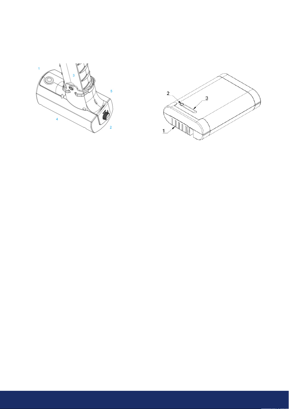
2.5.1 RRC2040 battery parts
2.5 Battery parts
The LF10 primary battery configuration is the RRC2040, which is a small portable battery in an integrating housing.
TheRRC2040 battery option is presented in Section 2.5.1, while the second battery option called the Tracer battery –
anexternal battery configuration – is described in Section 2.5.3.
2.5.2 RRC2040 external battery charger
The RRC2040 charger has two parts: the charger unit and the power supply unit. The charger unit has connectors for the
battery in the charging bay and a DC barrel input for power supply. The power supply has universal power supply input
for which the fitting power cable can be chosen, depending on the given region.
Image 3: RRC2040 battery housing Image 4: RRC2040 battery
1: Power button
2: Battery cover
3: Fixing screw
4: Battery housing
5: Lanyard attachment point
1: Battery connectors
2: Charge gauge button
3: Battery charge indicator
11
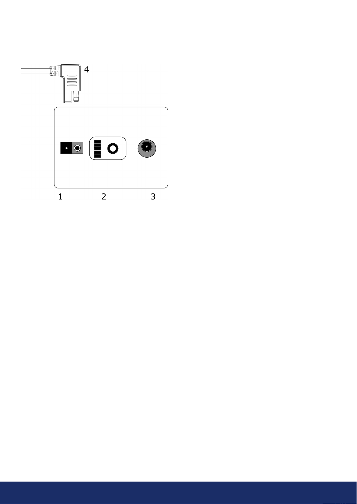
2.5.3 Tracer external battery parts
If you purchase the LF10 supplied with the Tracer external battery, see the battery parts below:
2.5.4 Tracer external battery charger
The charger for the Tracer battery is an AC/DC converter with an output capable of charging lithium iron phosphate
(LiFePO4) batteries. The charger has a universal single-phase power supply input, a status LED, and a charging output.
The charger is provided with a power supply cable including a plug compatible for the power socket outlets in your
region. The charger has a DC barrel plug at the end of the output cable for charging the battery. Do not use any battery
chargers other than ones approved by NL Acoustics.
2.6 Spare parts and accessories
Please ask your local reseller for information on what spare parts are available.
Image 5: Tracer external battery parts
Bottom: The main battery of the LF10
1: Output connector for the battery cable
2: Charge gauge
3: Battery charger connector
Top:
4: Battery cable connector

12
3. GETTING STARTED
The camera is powered by two sources of electricity: its own internal battery, and an external battery. The internal power
supply is a lithium-based rechargeable battery installed inside the camera. To optimize internal power supply life during first
operation, power on the LF10 camera for at least 45 minutes. When the internal battery needs to be recharged, the
camera will prompt the following message: Please keep the camera on. Before every use, make sure that the external battery
and its accessories are in good condition. The charge of the external battery may be low due to storage time at the supplier
and/or goods transport regulations. To ensure long battery lifetime, fully charge the batteries before their first use.
3.1 Charging
The main power source of the LF10 is an external battery: either the RRC2040 battery, or the Tracer. The batteries should
be charged fully before operating the device. Please note that the batteries should also be fully recharged before placing
them in storage.
3.1.1 Charging the RRC2040 battery
Before using the batteries, remember to charge them first. Fully recharging a completely discharged RRC2040 battery
usually takes about 2 to 3 hours. Please note that the battery should be charged at ambient temperatures between 0°C
and +40°C (32°F and 104°F). A new RRC2040 battery used under optimum environmental conditions yields up to 2.5
hours of usage.
The RRC2040 batteries and charger come delivered with the LF10. Only use the battery charger supplied with the LF10.
Please follow these instructions to charge the batteries:
1. Plug the DC barrel connector of the power supply unit into the RRC charger.
2. Plug the charger's power supply cable into the wall socket-outlet.
3. Ensure that the connectors of the battery and the charger bay are properly aligned when inserting the battery.
When inserted correctly, the battery sits firmly and straight. The charger light starts blinking when the battery is
properly connected.
When the battery starts charging, the charger light turns orange. When the battery is fully charged, the light turns
green. You can see how much the battery has charged by pressing the charge gauge. If the external battery needs to
becharged, the camera will prompt the following message: Low battery.
Color of the charging status LED Explanation
Off Not powered or no battery
Green Ready
Yellow Charging
Red Malfunction / temperature limits exceeded
Flashing/Changing Setting up
Number of LEDs on State of charge [%]
4 100-76
3 51-75
2 26-50
1 10-25
1 (flashing) <10
Charge gauge
The front side of the RRC2040 battery holds the
battery connectors, while the top side of the
battery holds the charge gauge button and the
battery charge display. To check the battery's
state of charge, press the charge gauge button
(Item 2 in Image 4) and the battery charge LEDs
will display will the charge percentage.
- NOTE: The LF10 camera is not intended to be used while the batteries are charging. Charge the battery only
when they are disconnected from the camera! -
- NOTE: Charge the batteries at temperatures between 0 °C and +40 °C (32 °F to 104 °F). -

13
3.1.2 Charging the Tracer external battery
Fully charging a discharged Tracer battery usually takes between 4 to 6 hours. Please note that the battery should be
charged at ambient temperatures between 0°C and +40°C (32°F and 104°F). A new Tracer battery used under optimum
environmental conditions yields up to 7 hours of usage. This depends, however, on multiple variables which may
decrease usage time, including the cell temperatures, the load, and the age (i.e. charging cycles) of the battery.
The Tracer battery and charger come delivered with the LF10. Only use the battery charger supplied with the LF10.
1. First, disconnect the battery cable from the battery output connector (Item 1 in Image 5).
2. Plug the charger's power supply cable into the wall socket-outlet.
3. Plug the DC barrel connector into the battery charging connector (Item 3 in Image 5).
When the status LED of the charger is red/yellow, the battery is charging. When the status LED of the charger is green
while the DC barrel connector is connected to the battery, the charge is complete. The status LED is also green when the
DC barrel connector is disconnected. If the external battery needs to be charged, the camera will prompt the following
message: Low battery.
Power supply cable
connected
Charger cable
connected Charger status LED
No No Off
Yes No Green
Yes Yes Red or yellow, charging
Yes Yes Green, fully charged
Charge gauge
Press the charge gauge button (Item 2 in Image 5)
totest the state of the battery charge. The indication
is approximate only, and the most accurate results are
aer 2 minutes of no charging. Note that if battery
displays no lights, the state of charge is empty. If the
battery fails to fully recharge within 12 hours, the
battery may be damaged.
LEDs State of charge
3 greens, 2 reds Full
2 greens, 2 reds Over 50%
1 green, 2 reds Over 20%
2 reds Less than 20% (recharge soon)
1 red Less than 10% (nearing automatic
switch-off)
No lights Empty
- NOTE: Do not leave the
battery unattended during
charging! -

14
3.2.1 Startup with the RRC2040 battery
The RRC2040 battery set for the LF10 includes two
batteries, a charger, a charger feeder cable, and
acountry-specific power supply cable.
Please follow the instructions below and see Image 6
to start the camera using the battery, and if you need to
attach the battery housing to the LF10 camera.
Aer you have attached the battery housing to the LF10,
open the lid (Item 3 in Image 7) by turning the knob of
the battery housing counterclockwise, and insert the
battery into the battery housing with the connectors
at the front and the charge gauge (Item 2 in Image 7)
facing upwards. Ensure the battery is inserted all the way
1: Unscrew and remove the lowest screw in the camera
handle. (Item 1 in Image 6) (tool: 2.5-mm hex socket
screwdriver, not included)
2: Insert the support spacer in the screw hole
(Item 2 in Image 6).
3: Insert the camera handle into the battery housing.
The housing is correctly positioned when the screw
hole of the battery housing is aligned with the lowest
screw hole of the camera handle (Item 3 in Image 6).
4: Screw the 30-mm hex screw through the housing
into the handle. Tighten firmly (Item 4 in Image 6).
1: Power switch button
2: RRC2040 battery in the correct position when for
inserting it into the housing
3: Battery cover
Image 6: Attaching the RRC2040 battery housing
Image 7: Inserting RRC2040 battery
inside the housing. Close the cover of the battery and
turn the knob clockwise to lock the cover. Press the ON/
OFF button (Item 1 in Image 7) at the front of the battery
housing to turn the camera on. The LED located on top of
the camera will turn red. The camera is now ready to use.
If the power LED of the LF10 camera blinks, your battery
has depleted its charge before startup.
When the power is ON, the red Power LED of the
camera is lit (Item 6 in Image 2). The system starts aer
approximately 10 to 15 seconds. The startup logo will
appear on the screen. Once the system setup has
completed, the LF10 camera’s user interface starts
automatically, and the camera is now ready to use.
The LF10 has internal system backup batteries which the
main battery charges while the LF10 is in use. At the first
system startup, it is recommended that you leave the
camera ON, powered by the main battery, for at least
45 minutes so that the internal backup batteries are
fullycharged.
If you wish to attach the wrist lanyard that comes with
the camera in the battery housing, you can find the
attachment point on top of the battery housing lid
(Item 5 in Image 3).
3.2 Startup
For startup, please see the sections below that provide instructions for starting up the camera using either the RRC2040
battery or Tracer battery.
15
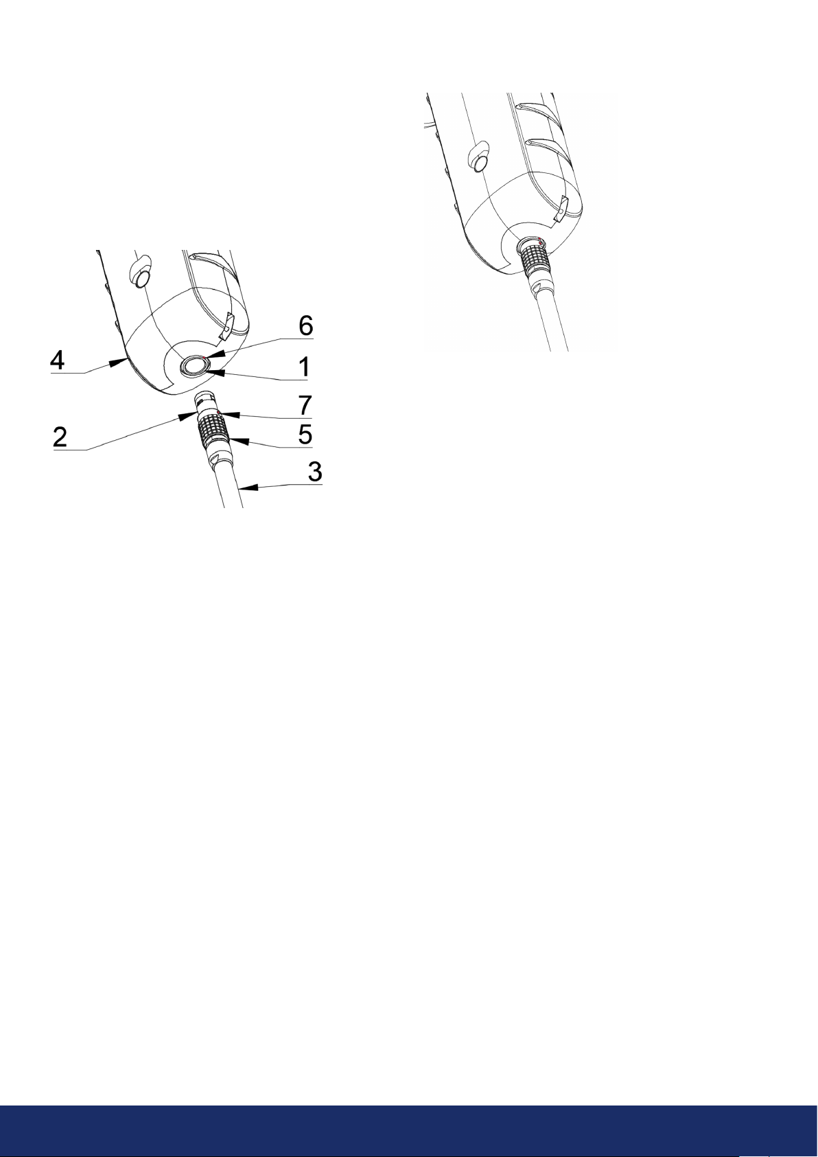
3.2.2 Startup with Tracer external battery
1. Attach the battery cable to the battery. There is only
one way to attach the connector of the battery cable
to the battery output connector. Push the connector
downwards all the way.
2. Attach the connector to the LF10 by following the
instructions in Image 8, with the orientation markings
facing the same way:
Both the LF10 and the battery cable have red alignment
markings (Item 6 and 7 in Image 8). They indicate the
position of the key and the slot of the connectors, thereby
ensuring proper alignment for connection. Secure the
battery cable connector using the locking ring (Items
6 and 7 in Image 8), and make sure that the alignment
markings of both connectors are neatly aligned before
inserting the battery cable. Then carefully insert the
battery cable connector into the LF10. The connectors
should lock audibly.
1: Input connector
2: Battery cable connector
3: Battery cable
4: LF10 handle
5: Connector lock ring
6: Input alignment Marking
7: Cable alignment Marking
Image 8: The various parts to consider when starting the
LF10 camera
Image 9: Battery cable inserted in the LF10 camera.
When the power is ON, the red Power LED of the
camera is lit (Item 6 in Image 2). The system starts aer
approximately 10 to 15 seconds. The startup logo will
appear on the screen. Once the system setup has
completed, the LF10 camera’s user interface starts
automatically, and the camera is now ready to use.
- NOTE: Hold the LF10 firmly by the handle. -
The LF10 has internal system backup batteries which the
main battery charges while the LF10 is in use.
At the first system startup, it is recommended that you
leave the camera ON, powered by the main battery, for at
least 45 minutes so that the internal backup batteries are
fully charged.

16
3.4.2 Shutdown with the Tracer external battery
To turn the LF10 camera off, simply disconnect the
battery connector from the LF10 camera.
1. Hold the battery cable connector by the lock ring
and pull it outwards. The lock ring will slide until it
releases the connection. Alternatively, disconnect
the cable from the battery.
2. The shutdown logo will appear, and the system
will safely and reliably shut down.
3. The camera’s red power LED will turn off once
shutdown has completed.
If you encounter a problem with the system, disconnect
the battery power and wait until the power LED turns
off. If shutdown takes more than 5 to 10 minutes aer
disconnecting the battery, contact NL Acoustics for service.
3.4 Shutdown
To shut the camera down, please see the sections below that provide instructions for turning the camera off using either
the RRC2040 battery or Tracer battery.
3.3 Device setup wizard
The first time the LF10 is powered up, the device setup
wizard will appear. The wizard will help you set up the
settings needed for using the device, such as the WiFi
settings (not supported in all regions), language, location,
and time zone. This information can be changed later via
the settings menu. Please see Section 4.7: Settings for
more details.
3.3.1 Device registration
Create an account and register your device on the
NLCloud service. Use the NL Cloud to store and view
the uploaded snapshots and videos, among other
functionalities (Section 7: NL Cloud). Please follow the on-
screen instructions given by the setup wizard in order to
register the device. You can also register the device later
in the network settings (Section 4.7.1: Network settings).
- NOTE: Do not pull the device by the cable or use any kind of pliers or tools to disconnect cables! -
3.4.1 Shutdown with RRC2040 battery
To turn off the LF10 camera, simply press the ON/OFF
button. When turned OFF, the button is in the up position.
1. Press down the ON/OFF button until it clicks and
rises up. The power is now switched off.
Alternatively, you can withdraw the battery from the
battery housing.
2. The shutdown logo will appear, and the system
will safely and reliably shut down.
3. The camera’s red power LED will turn off once
shutdown has completed.
If you encounter a problem with the system, you can
perform a hard shutdown by disconnecting the battery
power and waiting until the camera’s power LED turns
off. If shutdown takes more than 5 to 10 minutes aer
disconnecting the battery, contact NL Acoustics for service.

17
4. USER INTERFACE
You can control various LF10 functionalities and operations at the user interface. This section describes the functionalities
and the settings available to the user when operating the camera, such as the heatmap, snapshots and video capturing,
uploading and browsing through the snapshots, settings, real-time analysis, data transfer, and updates.
Image 10: Intensity of the sound source
4.1 Heatmap
The main view of the user interface shows the camera image with a heatmap overlay. The heatmap shows the location
of the strongest sound source (single-source mode) or multiple sound sources (multi-source mode). Each sound source
isshown by means of a single color according to the intensity of the sound source (see Image 10). The intensities range
from weak to medium to strong with respective color-coded schemes in green, yellow, and red, respectively.
In addition to the heatmap, the location of the strongest sound source is shown with a small crosshair. When taking
a snapshot, the sound arriving from the direction of the crosshair will be recorded and analyzed (Section 5: Air leak
detection features). The dB level of the sound from this direction is shown at the top of the screen.

18
4.2 Taking a snapshot
Press the Snapshot button to take a snapshot that
contains the current camera image and heatmap.
For analytics purposes, the snapshot includes a
short video (4 seconds) and an audio clip of the
strongest sound source. The video and audio clip are from
the preceding 4 seconds before you press the Snapshot
button. For this reason, you should keep the camera
steady for a few seconds before taking a snapshot,
inorder to get a clear signal from the source of interest.
Thedirection of the strongest sound source is shown with
a crosshair. Aer you have taken a snapshot, the camera
displays a screen where you can enter comments. The
camera also allows you to input the distance manually in
the screen by clicking the Change button that is shown
on-screen aer a snapshot is taken.
Aer entering such pieces of information, press the Save
button to save the snapshot. If at this point you choose
to not save the snapshot, press the Trash button in the
bottom le corner instead. Please note that if you use the
camera to photograph people, remember to ask their
consent prior to capturing any images.
4.3 Recording a video
Press the Video Recording button to the right
of the Snapshot button to start recording. Note that the
video length is limited to 5 minutes. To stop recording,
tap the video recording button again. Aer you have
finished recording, you can enter additional information
just like when taking a snapshot. You are also given the
option to save or erase the recorded video clip. You can
erase the clip by tapping the Trash button.
You can view the saved videos later in the NL Cloud, NL
Camera Viewer, or NL Camera Viewer Pro. However, you
cannot view the recorded videos on the camera itself, or by
using any other video player soware on your computer.
Please note that if you use the camera to take videos
showing people, remember to ask their consent prior
tocapturing any images.
4.4 Snapshot browser
The number of snapshots currently saved on the LF10 is
shown to the right of the Snapshot Browser button. If there
are two dots visible next to the number, snapshots are
currently being uploaded to the NL Cloud.
Press the Snapshot Browser button to look
through the snapshots you've taken. Thumbnails
of the snapshots are shown at the bottom of the
screen, and you can scroll through these horizontally.
When you press a thumbnail, the snapshot will be shown
together with some additional information.
Note that snapshots are not available in the Snapshot
Browser aer they have been uploaded to the NL Cloud
service, exported to a USB flash drive (see Section 4.10:
USB export), or exported with direct export functionality
to a PC (see Section 4.11: Direct data transfer).
4.4.1 Snapshot upload options
Press the Upload button to select the mode for
uploading your snapshots, and three options will
be displayed: enable the cloud upload, trigger
manual cloud upload, or direct data transfer.
Enable/disable automatic cloud upload:
Upload to cloud
With this functionality, you can enable or disable
automatic data upload to the NL Cloud. See Section 4.9:
Cloud upload for more information.
Trigger manual cloud upload:
Upload to cloud now
If you have disabled the automatic data upload, you can
manually trigger data upload to the NL Cloud. See Section
4.9: Cloud upload for more information.
Transfer snapshots directly to a PC without USB
sticks: Direct data transfer
This functionality lets you transfer data directly to NL
Camera Viewer Pro without using the USB export
functionality. See Section 4.11: Direct data transfer for
more information.
If you wish to transfer files to a USB stick, please see
Section 4.10: USB export.
4.4.2 Tagging snapshots
Snapshots can be assigned to a tag. Select a snapshot and
type on the screen the tag of your choice. This information
is then included in the metadata of the snapshot. The tags
can be used later in NL Camera Viewer Pro and NL Cloud
(see Sections 7 and 8) to sort your snapshots.

19
4.5 Zoom
The LF10 is equipped with a 2x digital
zoom that can be used for close-up
snapshots. Press the Zoom Buttons
tozoom in or zoom out. The zooming
in option increases the directional
resolution of the camera from 0.5° to 0.25°.
4.6 Quick settings
Press the Quick Settings button to show the
available quick settings. The possible settings
are listed below.
4.6.1 Screen brightness
The brightness of the display can be
adjusted by pressing the Brightness
button. This is useful for making the
display readily legible under differing
lighting conditions (indoors/outdoors).
4.6.2 Single-source / multi-source mode
Press the Single-source / Multi-source
button to toggle between the two
modes. In single-source mode, the
LF10 shows only the sound source with the highest
intensity (marked by a crosshair). If there are multiple
sound sources of equal or almost equal intensity as the
strongest sound source, the LF10 will show all these
sound sources as well.
In multi-source mode, the LF10 shows multiple sound
sources with different intensities. The sound source with
the highest intensity will be shown with a crosshair on
top. Not all sound sources will be shown. For example,
ifthere is a very strong dominant sound source, very
weak sound sources will not be visible at the same time.
To see weaker sound sources in either single-source or
multi-source mode, position and rotate the camera so that
stronger sound sources are outside the field of view. You
can also use the zoom button to limit the field of view.
4.7 Settings
Press the Settings button to show the available
settings. Please see the various settings in the
sections below.
4.7.1 Network settings
Press the Enable WiFi button to show the available
WiFisettings.
To be able to scan for and select a WiFi network, first
specify your location. Do this by pressing the Location
button. You will then see a list of locations to choose from.
If the selected WiFi location is incorrect, you may not be
able to connect to WiFi networks, or the WiFi connection
might not work properly.
When pressing the Select WiFi button, the camera will
scan for nearby WiFi networks. Aer the scan, a list of the
networks detected will be shown. If the WiFi network
you wish to connect to is not displayed as detected, try
moving closer to the WiFi access point. Once you find and
select the desired network, you will be asked to enter the
WiFi password. Please note that only secure, non-public
WiFi networks are supported. The LF10 accepts WiFi
networks that require password input, but not networks
that require both a username and password.
An icon representing the WiFi connection status and
strength is shown to the right of the Settings button:
Device registration
If you have not completed the device registration in the
setup wizard, you must first register the device with the
NL Cloud service to be able to upload snapshots to the
NLCloud. Please follow the on-screen instructions in
order to register the device.
Excellent WiFi connection strength.
Good WiFi connection strength.
Satisfactory WiFi connection strength.
Poor WiFi connection strength.
No WiFi connection.

20
4.7.2 Time settings
The current time and date are shown under the time
settings. Choose the correct time zone to see the
correct local time. The time and date are automatically
synchronized when connected to WiFi.
4.7.3 Advanced settings
Language
This option allows you to choose the desired user
interface language. The following languages are
supported:
Distance unit of measurement
The distance unit of measurement can be changed here
toeither meters (m) or feet ().
Reset settings
All settings can be reset to their default value by choosing
Reset settings. Please note that doing a settings reset
will not remove any snapshots, revert to any previous
soware version, or remove the device registration.
Available filters
In case the usage application requires the manual
selection of filters, this option lets you activate the
corresponding optimal filters for finding leaks. Change
the setting to Available filters: All to enable all filters. See
more information on the filters in Section 5.1: AutoFilter.
Remove all data
All user data and settings can be removed from the device
by pressing Remove all data. The snapshots and device
registration will be removed. All users currently paired
with this device will be unpaired from the device. To
continue operating the camera, proceed to pairing the
device again. The camera soware will not be reverted
toany previous versions.
Calibration mode
The NL Sonic Tester calibrator is available as an accessory
for periodically checking the accuracy of the LF10. For
more information, please contact your local distributor.
For details about the calibration mode, please see the
documentation provided with the NL Sonic Tester.
4.8 Real-time analysis
Real-time analysis results are shown on the display of the
camera’s screen, including the dB levels, leak rate, leak
cost, and the distance to the sound source.
The dB levels of the strongest sound source are shown
marked with a crosshair. The real-time analysis also
provides information about air leaks. The leak unit of
measurement is the estimation of the leak size in liters
per minute (l/min) or cubic feet per minute (CFM). The
leak cost is the estimated cost of the air leak detected
given in a specific currency as an energy cost, and these
parameters can be modified accordingly. For details,
seeSection 5: Air leak detection features.
The AutoDistance function is a feature from real-time
analysis. The LF10 estimates the distance from the camera
to the source of interest automatically. If you wish to input
a manual distance, the screen display prompts the +
and - signs, and you can use them to manually input an
estimated distance.
• Czech
• Danish
• Dutch
• English
• Estonian
• Finnish
• French
• German
• Greek
• Hungarian
• Indonesian
• Italian
• Japanese
• Korean
• Norwegian
• Polish
• Brazilian Portuguese
• Russian
• Simplified Chinese
• Spanish
• Swedish
• Thai
• Traditional Chinese
• Turkish
• Vietnamese
Table of contents
Other NL Acoustics Test Equipment manuals

Popular Test Equipment manuals by other brands


Redtech
Redtech TRAILERteck T05 user manual

Venmar
Venmar AVS Constructo 1.0 HRV user guide

Test Instrument Solutions
Test Instrument Solutions SafetyPAT operating manual

Hanna Instruments
Hanna Instruments HI 38078 instruction manual

Kistler
Kistler 5495C Series instruction manual

Waygate Technologies
Waygate Technologies DM5E Basic quick start guide

StoneL
StoneL DeviceNet CK464002A manual

Seica
Seica RAPID 220 Site preparation guide

Kingfisher
Kingfisher KI7400 Series Training manual

Kurth Electronic
Kurth Electronic CCTS-03 operating manual

SMART
SMART KANAAD SBT XTREME 3G Series user manual

Agilent Technologies
Agilent Technologies BERT Serial Getting started