NLI DN-2 Series User manual

NEWLONG INDUSTRIAL CO., LTD.
ml----
SEWING
MACHINE
HEAD
MODEL
=~O=O®
=~[LO=O@
=~W

For Operator Safety
T ha nk you f or p u rch asing the NLI
Model DN- HS Bag Sewing Machine Head.
( ) DN- HS
From the Library of Superior Sewing Machine & Supply LLC
2
• This
manual
contains the instructions
e.nd
precautions
for
using
the
Model
DN-2HS
Bag
Sewing
Machine
Head,
Be
sure
to
read
and
understand thls
manual
before
use
and
use the
machine
corTectly.
•
Keep
this
111BJ1Ual
near the
sewing
machine
for
easy
reference.
Be
SUI'e
to
attach this
manual
to the
machine
when
lending ortransfe.ning
it
to
another person or
company.
•
Plea.,e
orderthis
manual.
from
the nearest
NLI
office
ifit
is lost.
• The contents of
this manual
are
subject to change
without prior notice
for
improvement
and safety
pUJl)ose.
~Hazard
of
Being
Caught in the
Ma~hine
--
...
•
Be
careful,
when
you
insert a
bag
to be closed into
the
sewing
machine,
or your
fingers
may
be
caught in
the
machine
between
the
presserfoot and
feed
dog.
• A·Hazardous"
mark
is attached to the
machine.
When
sewing,
be
sure not to touch
on
the
machine.
£Hazard
of
Being
Cauiht
in
the
Machine
---..
• A
Needle
Bar and
Needle
Thread Take-Up are
movmg
at high speed. A"Hazardeus"
mark
is attached to the
machine.
When
the
machine
is operation, keep
fingers
e.nd
yourself
away
from
the
Needle
Bar
and
Needle
Thread Take-Up.
::=.
.:2- -a
:,;
!II•
• 2
fflUffl
~
v:,;
f:'~Jl:1,\J:fj\,\~t.:i!";ff
~.?
~~1,Y~To
•
=.,(f)
ltitfJltlfJ.l.l'i DN-2HS ~--}J.l~y:,;(f))li.1,
,-Ji
~tMJ:(f)tt;l:•Jl~~te.e~n
-c1,
'*To
;::'~fflnrm:.:(f)JlillHl
fJ.1-~~-
i":tdll"-<
~~._,
'o
~#
t-+~L:(IEt.,<~U<~~i.,
'o
•
=-(f)
llilamfJ.I
ill1MM(f)-t
J:f
R:,
,.,
,~
~~IJ.m
1r
,fte
1to.t;,
f*1ft.,-c<-n:~1t\,
DN-2HS
UtQffl~V1/dlAfit.,,
"£ft•:tMS!1JJ.l.g.
l'i.:(!)Jljdi~.fjfif~-·;::~t,.
-C(f.:~1,
,0
•
,:(f))lii\ilfJ.l·~~~tl,ft.iN"!::..2-P1/!/I.
Cf*>½mli!H&;Jn:;::-t±:1e<te~1,
'o
•
;::(f)
llilt&llfJ.I
•11••
!Pl
J:3;ftl-J::R½(f)ftll),
-1"$-f,I!
l.-
l;::~J!1"
?>~J::~~ibt>-:ti'
o
&-~~-------
• ~~1/l=tll~li*A
TQlltn-;1:,
tt•L.ll\.'btH>#.:r.*
l=ffi;r)~-~i6*M:lo-{:t1,;r){§.>'J'*i'
o
£-~~-------
•
Bt*-~J:.*3cfff'iilTUili"t'I/J'-'
'-C'-'
''*To
~Y-1/l=l-;t~tt-~-?~M-:>
-c11
'*T.
~Y1/tSJ!h1,
,-c1,
'o!:~t.t,
ftf41.!::J:-*3c~l=ffi~f*
~"'1ltfJ!1,
'°t'<~~l,
\0
&
-~'1:
WARNING
• The instruction manual and parts list is subjectto change without prior notice.
• ~(f)Jlill\ftfJ.1./,'~-o/!JAH:tift1PJJ:(!)7't~7ifflUqJfJ!TQ~tt,Si)tJ3;T0

From the Library of Superior Sewing Machine & Supply LLC
WARNING
PERSONAL
INJURY
MAY
RESULT
IF
THE
FOLLOWING
SAFETY
PRECAUTIONS
ARE
NOT
OBSERVED.
1.
BE
SURE
THE
AREA
SURROUNDING
MACHINE
IS
FREE
OF
ALL
HAZARDS
SUCH
AS
FIRE,
WATER,
OIL,
RUBBISH
OR
ANYTHING
THAT
CAN
CAUSE
INJURY.
2.
DO
NOT
OPERATE
MACHINE
IN
AN
EXPLOSIVE
AREA
OR
UNDER
WET
CONDITIONS.
THE
MACHINE
IS
NOT
AN
EXPLOSION-PROOF
TYPE
NOR
WATER-PROOF
TYPE.
3.
DO
NOT
OPERATE
MACHINE
BEFORE
READING
INSTRUCTION
MANUAL.
4.
DO
NOT
OPERATE
MACHINE
ON
VOLTAGES
OTHER
THAN
SPECIFIED
FOR
THE
MACHINE.
5.
BE
SURE
MACHINE
IS
CONNECTED
TO
BUILDING
ELECTRICAL
SAFETY
GROUND
(EARTH).
6.
BE
SURE
POWER
(AND
AIR
SUPPLY)
IS
OFF
BEFORE
PERFORMING
MACHINE
MAINTENANCE,
PARTS
REPLACEMENT,
ADJUSTMENTS
OR
CLEANING.
7.
DO
NOT
OPERATE
MACHINE
WITH
GUARDS
AND
COVERS
REMOVED.
8.
DO
NOT
TOUCH
KNIFE,
NEEDLE,
PULLEY,
BELT
AND
MOVING
PARTS
WHEN
MACHINE
IS
IN
OPERATION.
9.
BE
SURE
MACHINE
IS
PLACED
ON
A
SMOOTH
(LEVEL)
SURFACE
WHEN
PERFORMING
MAINTENANCE,
PARTS
REPLACEMENT,
ADJUSTMENTS,
CLEANING
OR
STORAGE.
10.
BE
SURE
THE
MATERIAL
TO
BE
SEWN
OR
CLOSED
COMPLIES
WITH
THE
MACHINE
SPECIFICATIONS.
11.
DO
NOT
USE
SPARE
PARTS
OTHER
THAN
"
NLI"
GENUINE
PARTS.
•
1.
UIUJ&O)Jilull::~i!&~®;:.-tmi~c!::t.J:~!k~,
71<,
:m,
iiJ~~t.J:c!::ti<t.J:1,
,ti,m:ti,~-c<t-=~1,
,0
2.
ffl~O)~l!iO)
if.>~Jl:tl
•
7J<iif!iti<@:till**l::tJ,tJ,~
Ji±Ji"t:(;t{lffl
~f.J:I,
\"(:(f,::~1,
\0
.::O)l!~(;t,
Rn•
~"
R1Jiifli~
"t:(;tif.,
LJ
*it
/v0
3.
:irx1&:ma_ijiJ:~~,-r~1v-r:ti,.;m**~ii:~~
-c<t=~
I,
\0
6.
l!~O)giiffi·!B~:3ttt·ruUl·:Rl;tffl~O)fiil::~"(
ffi5Jffi(&'CtI7-ID~ijJ-::,"((f.::~l,\0
1.
ii~:n,
{-ti<*nt.::~tm-r:r;t•*'~~~~t.J:I,
,-r:<
t.::~1,\0
8.
•**O)~~g:i(;t:n•.:.,11-,
it,
7'-
1
)-,
~JL,l---fO)
fil!ilJ1,
,-c1,
,~mr1r1::r;t-¥~Mnt.J:1,
,-r:<t.::~1,
,0
9.
l!*'O)~iiffi·!B~:3tti·fflffl~-ffl~~ii~O)t:2"1::
1;t.!jli:,t.J:~r1r1::11:1,
,-c<t-=~1,
,0
10.
*li!S?t:"9
~**1ti<l!**O)i±~(::'8"-::,-CI,
,~ti,m:ti,
~t<t.::~1,\0
11.
"=-.:i..-CJ~~I:¥(*)"tal!:iE$~~*(;t{lffl~f.J:I,'
-r:<t.::~1,\0
Identifying and Ordering Parts
Cautions When Using the Machine
Maintenance
From the Library of Superior Sewing Machine & Supply LLC
Where the construction permits, each part
is
stamped
with its part number. On
all
orders, please include part
number, part name
and
model name
of
machine.
Safety Rules
To prevent personal injury:
•
All
power sources to the machine must be turned off
before threading, oiling, adjusting or replacing parts.
•
All
cover and guards must be
in
position before operating
machine.
•
Do
not tamper with safety cover, guards, etc.,
while
machine
is
in
operation.
Safety Precautions
1)
Always
turn power off before threading, oiling, and
adjusting the machine or replacing parts.
2)
Wear safety glasses.
3)
Make sure, before starting the machine, that
all
covers
and shields are
in
place and closed.
4)
Do
not touch on the machine when it is run.
5)
Turn power off and make sure the cutter does not
operate before you put your fingers under the cutter
blades and the needles
to
adjust.
6)
Do
not touch on the machine when it is run.
• Please keep
in
mind
to handle the machine carefully and
to
maintain the machine
in
good condition.
• Thread fuzz or dust must be cleaned with air or brush on
throat plate,
in
the groove offeed dog or around looper
after the day's work.
• Wipe the area easy
to
rust with
oil
cloth.
• Check the machine
for
loose screws and tighten them, if
any, once a month.
•
Good
maintenance
will
prolong
the
machine
life.
ii
•
::=.:i
-
P::.,,
::1'I~
(
*-*)
~IILi!llJ~·ffl
/;:
l'i
D
N-2HS
0)*4iJ:E
tf~J'b:a:-~@L,
-C:}31'.Jj;To
•
:."tl:.JtO)~f';:l:,
/{-o/!};7.j-0)/{-o/:ffi:%,J::~fA;-C:."ffi;if-
<t-c.~lt'o
•
-fse:J=i=LJ:::'.::'~l=!Jclft,i/t&V-fse:Jtl
g=rO)it(ll'f~~i:ft,~, ~ 0)
ftl!tlf-Omft,J::·-ctgfl'.)
1;:<1t
,tiJ..g-f';:l:,
:t3Jh,J::fflt
,t;:.t-c.~j;l.,
tc.::=.:i
-
P:'./
::1'I~(*-*)~00i!U!m
1::."~~<
tt~
v
'o
r,!iJ
~O)~,
~fl~,
~~:ffi:%, ~1/:'./)mtf~~'
~1/:'./:ffi:%:a:-
:_"ffi;if-<t-c.~v
,j;-t
J::5:t3!HJiv
'v
,t;:.t.,j;-t"
o
1)
~ti!fj;l'.J
·
*·WH1,0),l::~O)*;imt.,,
*0)3'.tffi,,
~$,
Wl/ltlf,
tf~J'b3'.tffi:,
{;~'tj',~~fp~O)JVJl;:~,-r~~:a:--WJ0t<t-c.~
v
'o
2)
Wlff
llf
f!o~O)
,i::~
l'i~~,,i
:JJ'*
0)-fse:ffl
:a:-:t3-t"-t"
ilO
t.,
j;-t"o
3)
~tO)if
·.fJ/~-l'i~,i"~!l\ziMl:MilOt<t-c.~v'o
4)
.fJ/~-tt,1::·ntr,,Jj;0tv'Q::.,1:::a:-~~1.,tn•G~!lizit.,
t<
tc~v'o
5)
iJ-O)rf:,¥:a:-Jd1,Q,l::~f';:l:,
~,-rm~:a:--WJ0t<tc~lt'o
{~;f:!Wl/lllfO),J::~f';:l:,
~,-rm~:a:--WJl'.l~1/:'./i1!m/Ji3>ftv
,::_,i::
:a:-~~t.,
tn•Gft~:a:-ff0t<tc~v'o
• ~1/:'./.li"l$l'i~~ft,J,~ft$J'1=1n•Gl±l*J::n!0t1t'j;To
ti:~~<
J&:¥&5
,i::,i::t
1:
m-
1:mvm
1:,r,,m+t-c
<tc~v
,0
•
-~
O)ft~n!~Tt.,j;L,fc.G,
if-fJiO)J::,
~!J~O)f$\:O)
q:r,
;v-r~-O)j;:bl'.Jl;:~j:0fdi::.1'.l~l'i~n1t'f:1&1'.l
~v't<tc~v'o
•
-¥
AnO)
~ UIIU'i~~O)~ifuf;:~9t.,j;-t"O)-C:."r.t~
<tc~v'o

From the Library of Superior Sewing Machine & Supply LLC
CONTENTS/
~
{X
1.Specifications/
{±~
----------------------2
2.The Points Before
Operation/~~OOO)im~
-------------2
3.Threading/
*iffiL,~
----------------------3
4.Lubrication /~tlE
--------------------4
5.Aqjustment/ji}Wf
-------------------5
1 Looper (1v~/~~O)IDl3~)
.............................................................................
5
1-1 Check of Looper Travel Distance
(;v~,,~~O)~l/Jii)
..................................
5
1-2
Check of Dimension of Needle
Center
to
Looper Point
(it~il~t:J,1,,~,,~~0);'cft#.l'i--c:O),frt)
...................................................
6
1-3
Check of Height of Needle and Looper (if-0)
rWJ
~)
..
..
..
..
..
..
..
..
..
..
..
..
..
..
..
..
..
..
..
.. 6
1-4
Clearance between Needle and Looper
(jtc!::;v~/~~O)~j~,~~)
...................
7
2 Feed Mechanism
(*~
~f*O)IDl3~)
...............................................................
8
2-1 Positioning of Feed
Lift
Eccentric Cam
(*!J
J:
r:b
.b.O){ftfft:f;R:66)
...................
8
2-2
Needle Guide and Loop Retainer
(jtjJ,1F,&rJ;i,~:fjJ,1j..:'O)~~)
................
8
2-3
Feed
Dog
(*!J~O)wl3~)
.......................................................................
9
a) Adjustment
in
Crosswise Direction
(tc.~O)wl3~)
........................................
9
b)
Adjustment
in
Longitudinal Direction
(trHfO)~~)
.....................................
9
c) Height Adjustment (J:r O)wl3~)
............................................................
9
2-4
Change of Stitch Spacing
(*-i
§
~jO)~J!)
..................................................
10
3
Presser
Foot
(1'.::r:~O)~~)
.......................................................................
11
3-1 Positioning of
Presser
Bar Connection
(1'.::r:.?7'':\=-0){ftffi:f;R:66)
......................
11
3-2
Pressure
Adjustment of
Presser
Foot Ass'y (1'.::r:~O)fEjJIDl3~)
....................
11
4 Needle Setting
(if-O)!&{tlt:n)
.....................................................................
12
5.
Throat Plate
(jtf)ltO)~~)
..........................................................................
12
6 Adjustment for Single Thread Sewing
(1*iffl*-i1t
,O)~~)
......................................
13
6-1 Distance between Looper and Needle (if-c!::;v~/~~O)]Eg/U)
..........................
13
6-2
Check Height of Needle Bar (if-.O)rWJ~)
..................................................
13
6-3
Fixing
Throat Plate Thread Retainer (if-f)ltJRO)!&{tlt)
..................................
13
6-4
Check of Looper Travel Distance
(;i,~,,~~O)~l/Jii)
..................................
13
6.Troubleshooting/:3:"1/~0)1'7~;vO)J)j{~c!::::M;r&
---------14,
15
Parts
List/$
£;fl!t.
....................................................................................
17-
Numerical index of
Parts/r~--o/*51
........................................................
34,
35
List
of
Screw, Nut &
Washer/*:/
...
To/
1'
...
17o/"1/1"---~~
................. 36
..
37

From the Library of Superior Sewing Machine & Supply LLC
1.
Specifications/ftm
Model
DN-2HS/DN-2LHS
DN-2W
(~fl.81J)
Maximum
speed
(:i'ii@i@J~~)
2,B00rpm 2,B00rpm
Stitch
range
(~~i)
Note)
r_l
7.....,12mm
7
......
llmm
Seam
(~
§
ru:i:t)
Double
thread
chain
stitch (type 401) =m~~ (401)
No.
of
Needle
(it~)
1-needle (1
Jl;;:ij-)
2-needle (2
Jl;;:ij-)
No.
of
Thread(*~)
2-thread (2
**)
4-thread (4
**)
Needle
size
(iJ-ru:rt)
DR
X 2-#25
or
#26
UYl43GS-200
or
230
Lubrication
C*irlliliJ:rt)
automatic (oil-bath system) §
ib*irllil
(;:t,{;J.,/'{.A;i:t)
Note)
PP
woven
cloth
bag
7
......
10.5mm
:>!<:Parts
to
Replace
for
Type
of
Bag.
r_l)PP::7PA~~ffl
O)~~
7
~
10.5mm
*ffl~JJIH~J:7.JJ!!J~·itti·tifl.:r.~
~fiirnu
,~m
~f~r,ti:::,--cflc*O)im
¥)
O)~o/
r--c::=
~ffl
<
tc.2!:v
'o
Model
(~fjq5)
DN-2HS
DN-2LHS
DN-2W
Bag
Type
Paper
bag
Hessian
or
PP
Paper
bag
PP
woven
cloth
Paper &
hessian
~flt~
woven cloth bag
bag
laminated
bag
Parts
Name,
C*J£~ffl)
(tllf•PP/PE
(~~ffl)
(PP/PE
(~.1£-tllf7~
::7PA~ffl) ::7PA~ffl)
-*-r~ffl)
Parts
No,
lflh1i~·
'lflh1i:#%
Feed
Dog
(J!!J~)
014311
014291 024121
034202 034203
Throat Plate (ij-t\()
014241
014221 024091
034192 034193
Presser
Foot
(tifl.:r.~)
012201A
012211A 022081A
032342A 032343A
2.
The Points Before
Operation/~~jWO)i{I~
• Oil the area through which thread passes, the tension
disc, the thread guide, looper, etc.
(Note:An anticorrosive agent
is
applied
to
the machines
at the factory,
in
order
to
prevent rusting. It
is
necessary
to
use
oil
to remove this agent. or it
may
prevent the
thread
from
passing smoothly.)
• Confirm that the machine has been threaded as per the
instructions
3.
in
the manual.
• Confirm that the machine has been lubricated as per the
instructions
4.
in
the manual.
2
•
fWffllt.,
·c
~v:,,,~W~-tx-Cil~T7.Jb~IJ:,
:ff.:O)im7.JliiBi\
ff.:
wlil--r
•
:ff.::Jf-1F·
1v-/~-f.cc:'l~!.16,f'lm~~1.,
--c<tc.2!:
V
\o
~v:,,,f~IJ:,
~O)§e1'_~1i.15¢'tc~I~/±lfi/fl!ifl~~Jr.~lli!
~~--::i--Cv
'~To
~lr.~lm~~~l.,f.cv
,.1:::ff.:iJ,AA-AI~
mE:t1J
.c
v
\:
.
.1:'.
t,,
ih
¥J
~To
•
ililiilfiH~!-16,f'*iml.,O)m~~J!--C,
:ff.:imL,iJ,JEU\:
.
./:'.
~lit~L-
--c<tt.2!:v\
•
ii~
1W
f
~!-16,
f'~llil
0)
m
~
~w'Vv
--C,
*irllil
::1J7't?
t,,
lE
U
,_:_
.1:'.~1i'{l[~l.,
t<tc.2!:v'a

From the Library of Superior Sewing Machine & Supply LLC
3.
Threading
/ -*iiL,
IDN-2HS
I
DN-2W
Nt1eoleToi
ea
~
Ll;,¼)
21
L.ooger
ihr~~
CF
,Y,
) .
ll
IDN-2LHS I
From the Library of Superior Sewing Machine & Supply LLC
4. Lubrication/**
7EB
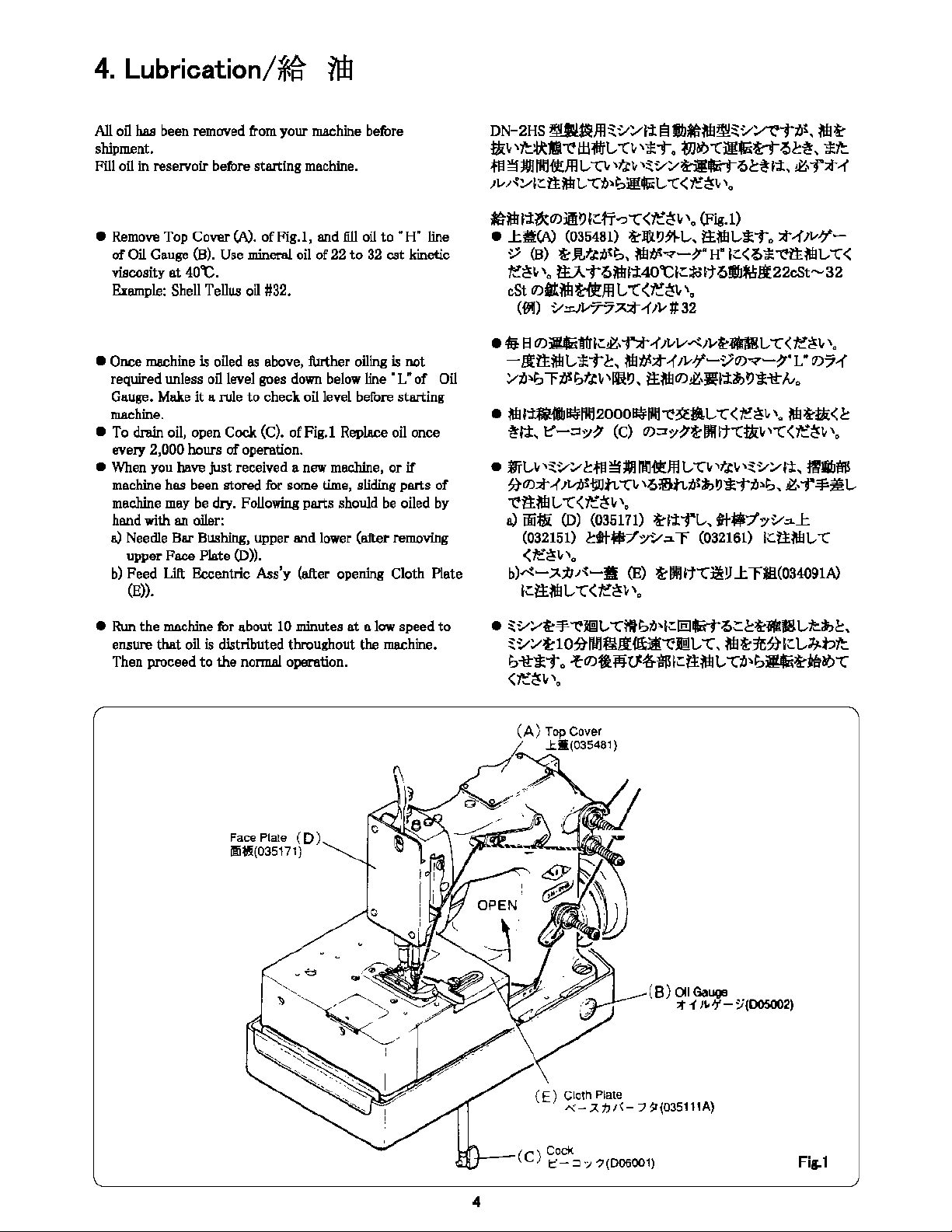
All
oil
has been
removed
from
your
machine
betbre
shipment.
Fill
oil
in
reservoir betbre starting
machine.
•
Remove
Top
Cover
(A).
ofFig.I, and fill
oil
to
"H"
line
of
Oil
Gauge
(B).
Use
mineral
oil
of
22
to
32
est kinetic
viscosity at
40°C.
Example:
Shell
Tellu.s
oil
#32.
• Once
ma.chine
is
oiled
as
above, further
oiling
is not
required unless
oil
level
goes
down
below
line
•
L"
of
Oil
Gauge.
Make
it a role to check
oil
level before starting
machine.
•
To
drain oil, open Cock (C). ofFig.I
Replace
oil
once
every 2,000 hours
of
operation.
•
When
you
have just received a
new
machine,
or
if
machine
has
been
stored
for
some
time,
sliding
parts of
machine
may
be
dry.
Following
parts should
be
oiled
by
hand
with
an oiler:
a)
Needle
Bar
Bushing,
upper and
lower
(after
removing
upper Face Plate (D)).
b)
Feed Llft Bccentric A$s'y (after
opening
Cloth Plate
(E)).
• Run the
machine
tbr about
10
minutes at a
low
speed
to
en.sure
that
oil
is distributed throughout the
machine.
Then proceed
to
the
normal
operation.
4
DN-2HS
~ffl~v~-tt
elbMNl~~v1/'t"-ttJt,
NI~
tJti.,
'7't:lil!ll~l±l-.rL-
-c1,
'"~-to
t}Jbl.>-CMGtt-?>~~,
*1t
.ffJ~MIH'ltl!fflL,
-ci..
,t,c1,
'~v1/dl1-t-?>t!J'1,
~--r*-<
,..,.,~~,:::ttNIL-
-Ct/lb:i!15'L-
-c<~~i.,
'o
~NIJ-J:~O)Jffit)l.'.:.fi-?"(<~~1,\o
(Fig.l)
•
..1:itiW
(035481)
~J&t)~t.,,
i:tNIL-j;-t.,
*-<ivl/-
V (B) t-JUttJlb,
Nlt/S"'7-~·
H"
l:::<-?>*~ttNIL-
-C<
~~\,
,.,
ft.A-t-?>Nlli40"Cl::::folt-?>lb~.!t22cSt-32
cSt O)a!N!~ffll,
-C<l!~1,
'.
(011)
v.:i:1v?°5~-1',v#32
•
4iJ
a
O)•tt11:::~,ff-1'1vv~,1,,~-t.,
-c<~~1,,"
-lfttNIL-*"t~, Nltl~*-1'1vJ/-V0)"'7-~·1•0)7-{
1/ti~;
""FtJSbf.;!1,\lfit),
i:tN!O)~,
••
';t,,t)j;-tt/v.,
• Nll~~lll'l2000~111'1~3f-l,
-c<,e~1,
,.,
Nl~ta:<t
~ft,
t"-:3:Y~
(C)
O)::ro/~f:DIHt-CtJli.,
'"'C<~~i,
,,,
•
ffit.,i.,
'~v~
~.ffJ
~M
111:l~ffl
t.,
-ci.,
,tl\t
,~v::.,fi,
tllba!S
~O),t-,<
,~tWn
-ci..
'-?>!inti~"t)*-tti~;,
~-
i"-¥:~t.,
~ltNIL--C<~~1,,o
a)
iiiffi:
(D)
{035171)
~1'1i"L-,
tt•-f
o/V.::L..I:
co321so
~tttitl7':,,v.:ir
co321so
l:::ttNIL-
-c
(7'!~1,,0
b)~-~1J.1{-11
CE>
t-lll•t-c~!J
J:
ra<os4091A)
l;:i:tN!L-
-c<~~1,
,
..
• ~v::.,~-¥~Jl!ll,-cmb1N;:leJl1-t-?>~t~ifKIIL,~,,t,
~v::.,f:lO~fll:l§fffU"(iJml,
-C,
Nlt-~~l:::L--'J.btt
h~*-t"
~O)•
flivt45-itm:1tN1
L-
-cti~b-~teab
-c
<~~\,'o
(E) Cloth Plate
,..._-~t,1<-""J
1'(035111A)
(C)
~0~:::i-;;?(006001)
Fig.1

From the Library of Superior Sewing Machine & Supply LLC
5.
Aqjustment/f,il
!I!!!:
Your machine has been properly adjusted before shipment
at
our plant.
If,
however, adjustments
are
required
at
your
end due
to
disusembly, repair, or parts replacement,
obsruve instructions given below.
1 LOOPER
1-1 Check of Looper Travel Distance
Looper (!) travel distence, (A)
of
Fig.2, should
be
25
to
26mm.
To adjust, loosen screw (a) end
tum
Eccentric Ball (c)
of
Looper Bell Crank Connection
Rod
©
cloclcwi.se
with a
screw driver, until correct position is obtained.
CAUTION
1.
Measure
dimension
as
Looper
(D
goes around Needle
@.
2.
Loosen
nut
(b) of
Fig.2,
and
align
eccentricity of
Eccentric Ball (d)
of
Looper Connectin1 Rod Aaa'y@
with line (x) connecting
centers
of Looper
Bell
Crank
@)
shaft and ball mounted.
Keep alignment by tentatively fastening nut (b) during
above a~ustment.
3.
For positioning eccentricity
of
Eccentric Ball (c) of
Looper Bell Crank Connection
Rod<Z.),
turn Eccenbic Ball
(c).
and
find a position where
nut
(b) is placed
Ill
the
highest level.
Keep
this position
by
tentatively fastenin1
screw (a) during above a~ustment.
A•25-26mn
l:-
----"5v Needle
DN-2HS'I!!;:c,:.,-t;t\llqj:,?iffl[iEtl\il!l!t'.l-
1:
t!lllif
L-
1:1
'lie
-r,<,
!lil
,II,
31:ll'l1'1?lllll•',11Jl!ICfl~>lel-ttt,, !XUJlllll
:J,!Jit'.$/i!ICL,1:Ji!i!L,
1:(;\'"'1
'•
,
}~-,
(-OJ!llllf
1-1 11,-11-0>ll!IIJA
,v-,-{-(DQ)Jl:ltJ:A:~Fig.2 't'ff..Til~, A=25--26mm
ICfloJ:?ICllJ!i!L,
1:(;\'"'1
'•
Pilffl.1i~ti,
*~
a til~-c"!J,,-.,.{-o-::;.,f,:'@(7).::r::.~i!1/
,t--,,
c t'.1':,-1',<-1?;/';lcllilL-U!i!T'->.
ll&•J!I
1.
,.-,
(-(D
>l'tl®
O>**>'J
~ll!~J:?l=L.
,::,t
!!~
it')
*"t·
2.
Fig.2
OJt""Jj..
b
:f&dJif'-JL,~31':.,H!l@O)Z~-tC,.,
1/l-
Jl,dO):i:~-1!!/fl'liRb<,
-<1•1'5!/1
©0>.;!';1:1/l
-
1•1111
t-llt;!';~li!;-0:ilill
(X)
.t
O>
.t
I=<
oJ:?
l=L.
"Ct"-:,
~
b~ililill!IJL-*"t.
3.
}L,-J'(-CJ"Ji-!°@O)I.~-t!:.,,K-JL, C
O)I.~-t!:.,m:c
la:, :i:'\'--l!:,;!l-1•~BL-,::, 1--,~ b
>l':IH,lli<t,.~fl',:
11:1=t,.~,1:-;1=t.
"C,
*~
a ~ililill!IJL-*"t.
8•5.5mm
)l,-)'\-
Looper
1
'\11,?5/?
Looper
Bel
l
Cronk
0
;tf
'"
~
;'I
1
:,
r-
rn
Looper
Connec1ing
Rod
Ass'y
b
T·,
I--
Nut
0
I*t
:.,;j;"-JI,
Eccentric
Bal
I
•
a
~
;.:
Sere..-
JI,-/~-
D
..
;
r-:
Looper
Be
11
Cr·ank
Corinect
i
on
Rod
----·~
.I
'=1=-
t?
:.,
;r,·
-
Jl,
Eccentric
Boll
Fig.2
From the Library of Superior Sewing Machine & Supply LLC
5.
Aqjustment/wlff
!i!f
1-2
Check
of
Dimension
of
Needle Center to Looper
point
Distance between Needle
center
and Looper point, (B)
of
Fig.2,
is
5.5mm,
when
Looper
(D
is
in
the extreme right.
To
obtain this dimension, loosen nut (b), and
tum
Eccentric
Ball
(d)
of
Looper Connecting
Rod
AE.s'y
@ clockwise
when
dimension (B)
is
smaller than
5.5mm,
and counterclockwise
when
it
is
larger than
5.5mm.
After adjustment, check looper travel distance W and
confirm
it
is
in
specified
range
of
25
to
26mm.
Ifnot
adjust
Eccentric
Ball
(c)
of
Looper
Bell
Crank Connection
Rod
®
again
while
checking dimension between Needle @ center
and Looper
(D
point, until both dimension.
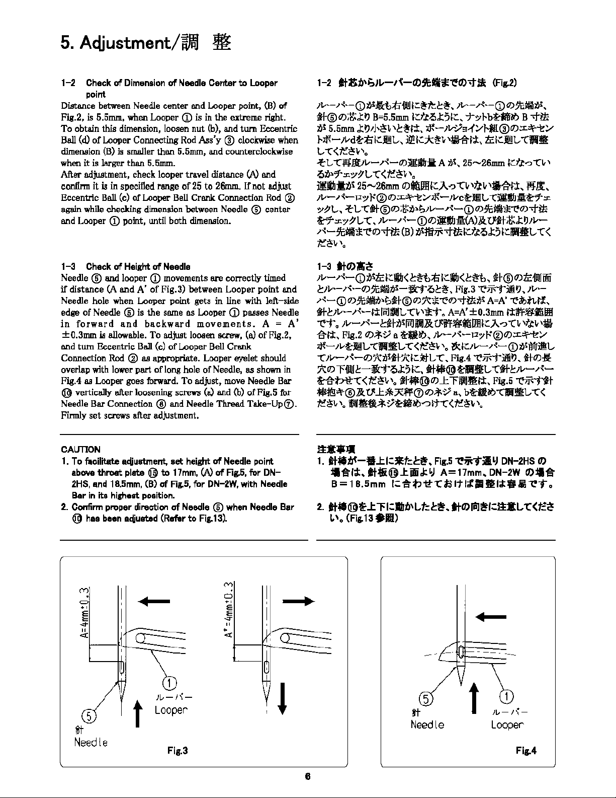
1-3 Check
of
Height
of
Needle
Needle ® and looper
(D
movements are correctly timed
if
distance (A and A' of Fig.3) between Looper point and
Needle hole when Looper point gets in line with left-side
edge
of
Needle ® is
the
same as Looper
(D
passes Needle
in
forward
and
backward
movements.
A =
A'
±0.3mm
iB
allowable. To adjust loosen screw, (a)
ofFig.2,
and
tum
¢ric
Ball (c)
of
Looper Bell Crank
Connection Rod ®
as
appropriate. Looper eyelet should
overlap with lower
part
of
long hole
of
Needle,
as
shown in
Fig.4
as
Looper goes forward. To adjust, move Needle Bar
@ vertically after loosening screws (a) and (b) of Fig.5 for
Needle Bar Connection @ and Needle Thread
Take-Up(v.
Firmly
set
screws after adjustment.
CAUTION
1.
To facilitate aqjustment,
set
height
of
Needle point
above
throat
plate @ to 17mm, W
of
Flg.5,
for
DN-
2HS, and 18.5mm, (B)
of
Rg.5,
for
DN-2W,
with Needle
Bar
in
its highest position.
2.
Confirm
proper direction
of
Needle @ when Needle Bar
@ has been aqjusted (Refer
to
Fig.13).
=
.'
~
~
,v-
r~-(D
il~:Al:tli"ill!I
I::
~ft.!:~,
,v-
,-{-(D
OJ;'c;MNti~.
,t/-@<DZJ:~
Ba5.5mm
lcft'.,J:;ilc, T7rbt-lil!O'> B
-tlk
ii~
5.5mm
.t
t),J,~l,
'.!:~l:t,
.f--
JV';.'9--(:.,,J-.ffi@OJ:L.;:\'-"'e':.,,
,,f,-1vdt,;/;ICJil!l,,
J2'1C*~-'~I±,
/clCJil!l,
"C11fiJI!!
vc<t-'~•',
-{'l,
-C:jij!lJi,-,-{-O)~llJ:il
A i)S, 25-26mm l.:f,t-:,-CV'
Otil7".::i::.7P°l,
-C(ft"~V
'•
il!l!t•'25-26mm
C/lill!l!IIIC),-c,
-C,
,t,,
,1111N1,
l'!'!t,
JV-
,1{-
Po/}.'"@O).:L.;:\'-"'e':.,,,N-/VC~ffi[l,-Cill!J::l;~7":r.
,,;,i,, 'let,-Cilt@<D;t;,~,v-,<-(D<DltiJ!!!1t1'<D-t/k
tt.::i::.o/P-L
-c.
,i,-,-{-(DOJil:l!I-AW&.tnt-~.ttJ,v-
,<-JtiJ!!!1t1'<D-t/k
(B)
;lffiij<.J-!l,lcft'.,J:;iIClilll!'l,
-C
<
t:~l-
\,
1-3
tlO>;i!;~
1v-,<-CD•'lclc!l!<l:1!b;/;lc!l!<l:1!b,
il@<D/ciJQJi!ii
.!:1t.--,1{-QJ;'c;MNti~-ttC.!:!. Fig.3 -e,jf-;--tiilJ,
,v-
,1{-(D
OJ;'c;~ill~lJ-@
OJ
.1'::*-'e'OJ-t'*il~
A==A'
'e3';>tL,t!,
1*.!:1t.--,-{-l:tlmi'ffl,
-Cl-
'*-i'.
A==A'
±0.3mm
1:t~.$:ili'ilffl
"'e'T
O
JV-
,1{-cif-i)S
lmffll&.
at'F~«llfflIi:}..-:,
·n
,flV
,;11-
~l:t.
Fig.2
OJ..t-~
a
&tf!i;,
Jt.,-,1{-i:zo/J-.'"@OJ.:L.~:.,,
,N-,1V.f:'.m!VCll!!lf:l,-C<f-:~i,,. ~l.:11,,-,1{-(Dti~lfiiil;l,
-c,i,-,1{-0J'.Ail~tt'.Al::j:j-L
-c.
Fis.4
'"t'"jf-;-TiiltJ.
t+OJ:!:
.'/\:OJ
r-111!1.!::-!i:TQ.t;1.:,
tt-fff@t-ll§L
-ctt-c!::,v-,-{-
Hl-t>-lt-c<t-'~•'•
,t/-lll<@<DJcl'~iJl!!tl:,
Fig.51'ii<-ttl
[email protected]__c!l,;R1'l'CT)<Di<;!'
a,
bti!IO'>"Cll'lll!l,
,<
t-'~-
'· i(iJl!!ji,t,;!'t,!*O'>--:>lt-C<f-'~-
'·
ttt:•lll
1.
tt•lft-'l!.tl=*t=I:~,
Flg.5
~;;i"j";!<J DN-2HS
0)
'l!Jl:f;I;,
[email protected]!ii.l:•J
A=17mm,
DN-2W
O>'l!Jl;
B =1B.Smm
I=
jl:V -tt-C
tl
It
f;f
111
!I!
I.I:
111
ii,
~T
•
2.
tt•@l!'.t
,l=IIJn,t,tcl:i!t. tlO)P'Ji!tl=ttt:t,
-c<t=~
l,\., (Fig.13:t=lffl.)
"
«
~
1--lf'+----------=
5
tt
Need
le t
Jl,-1'\-
Looper
Fig.3
~,,b
I
'l
•
Needle
Jl,-/\-
Looper
Fig..4
From the Library of Superior Sewing Machine & Supply LLC
5.
Aqjustment/w,'/J :If
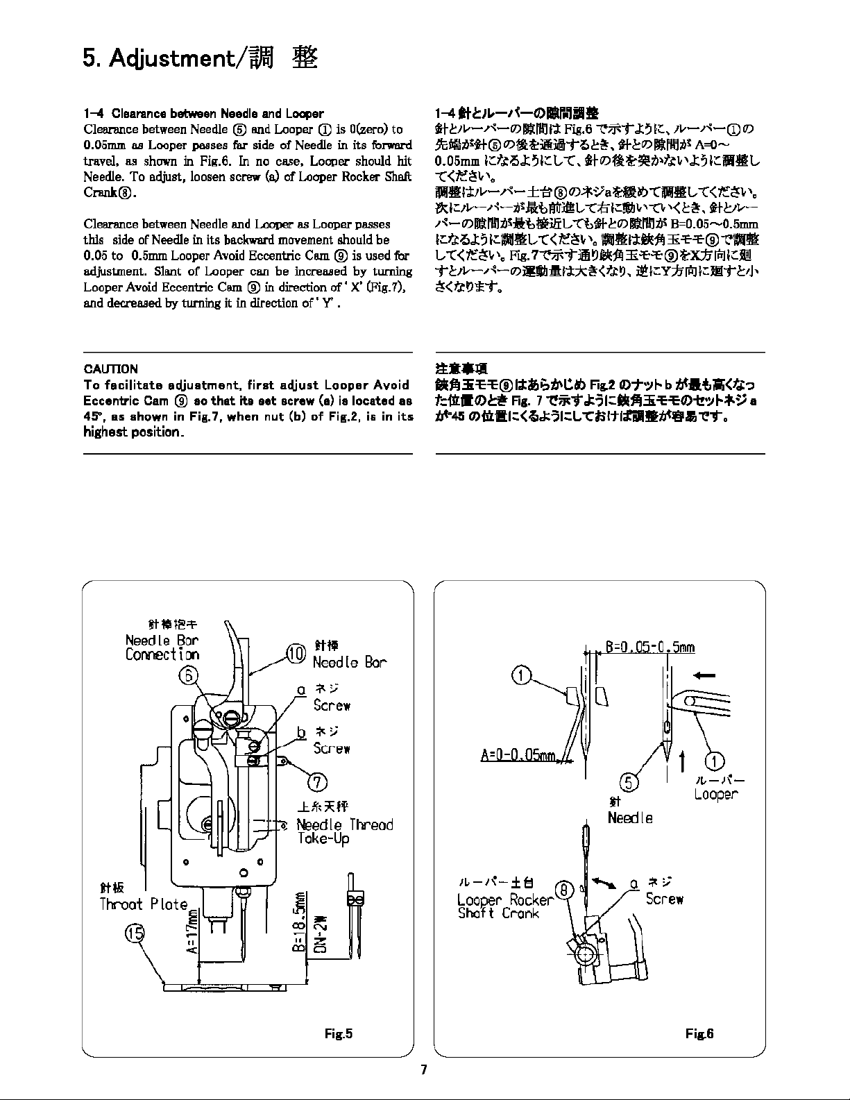
1-4
Clearance between Needle
and
Looper
Cleanmce between Needle ®
lllld
Looper
(D
is
O(zero)
to
0.05mm
as
Looper passes far side
of
Needle in its forward
travel, as shown in Fig.6.
In
no case, Looper should
hit
Needle. To adjust, loosen screw (a) of Looper Rocker Shaft
Crank@.
Clearance between Needle and Looper
as
Looper passes
this side of Needle in its backward movement should be
0.05 to 0.5mm Looper
Avoid
Eccentric Cam ® is used for
adjustment.
SlBnt
of Looper can be increased by turrring
Looper
Avoid
Eccentric Cam @
in
direction
of'
X'
(Fig.7),
and decreased
by
turning it in direction
of'
Y'
.
CAUTION
To
facilitate
adjustment,
first
adjust
Looper
Avoid
Eccentric
Cam
® ao
that
ita
aet
screw (a)
ia
located
aa
45\
as
shown
in Fig.7,
when
nut
(b)
of
Fig.2, is in
its
highest position.
tt"'!@S'
Needle Bar
ID
tiff
Connectioo
Needle
Bar
6 a
*;;
Screw
~;.;
Screw
7
.l
~,"'ff
t-laedle
Thread
Toke-Up
0 0
0
tt!li
~
Throat
Plate~ .
..
co "'
--•
" "
"'
< D
Fig.5
7
1--4
tt1:,•-,<-0>llllr,,iilllt
it.!::1v-,.-i:-QJ;J:l'ffli'i:
Fig.6
""{'i'~i"
J:;
f;::.,
11,,-,.-<:-(D
(l)
Js~•'tl@<Dl,l~;g;iilli"'->b!.
tll:<D!li(IIM'
A=0-
0.05mm
l;:::ft.J!>J:;
1;::
L,
-C,
j-f-(l)flt-'3il!tJ~tti.-
,J:;
l;::Jllffi:L,
-C<:fe~i.,,o
JllffiJj:JJ.,-,.-.:-±i:r@OJ-*~a
~~
-CJllHIL-
'C(
~~\,
'o
i,,1c,,-,<-,<Jiltiltril!n.,
--C:/,lc!IIJ,
,--c,
'<b!.
tll:Jv-
,,.::-
(l)ffl:kl'ffltJS:11:1:,ftE.!IL,
""C'Mff-.!::(l)
l!lll'ffltJS
B=0.05--0.5mm
lcfl'->J:
5
lcljfllJIH.,
--C
<
/,'~;
'•
ljfllJl!i,J:t/<j!
3i
'le'le@
't'llfll!
L,
--C
<
il:/!o
'•
Fig.
7't'jji-j"A~
tl<i!
3i
s,s,
@f:Jct;
'"1
ICil!
i"
l:1v-,<-<D~!IIJ:l:i,J:;Jc,!<t,~,
~
ICY:/,
'"1
ICl!li"
l:1J,
l!<t.i:~>lei".
1ta•J11
M1!3i'E'E@l;tilr,;;t,,tlb
Fo~2
0)1'-:,f- bti'IU,;;;<t~-,
t:il'LSO>I:~
Fog.
7
'l!;;iT
.l:';icM1!3i'E'EO>-t?-:,f-*;;a
t,t-45
Q)f;ljl!Jc<{>.l:';lcl.,
--Ct.lltlfill!lti'l!P.1,
'l!T.
-0.
mm
5
tt
Neoole
......._
a~;;
Screw
/t,-)~-
Looper
Fig.6
From the Library of Superior Sewing Machine & Supply LLC
5.
Aqjustment/wlff
!i!f
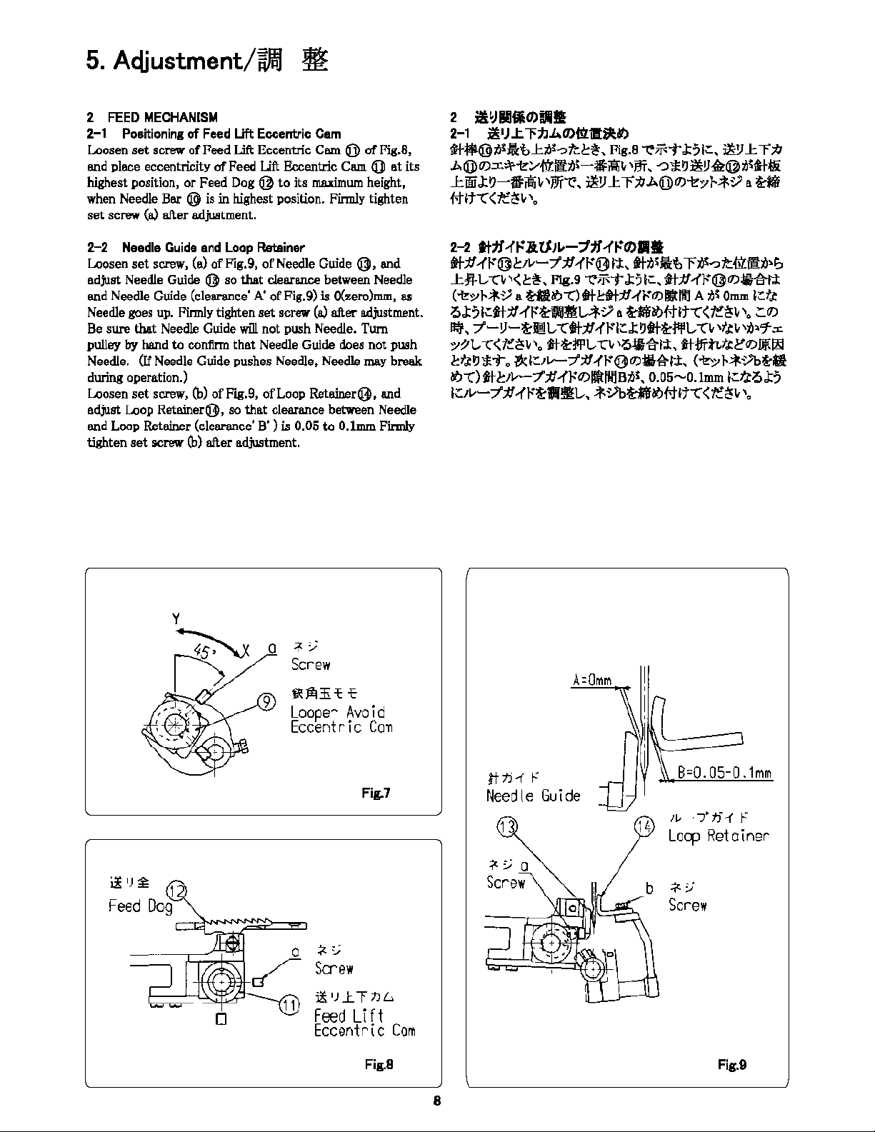
2
FEED
MECHANISM
2-1 Positioning
of
Feed Uft Eccentric Cam
Loosen
set
screw ofFeed Llft Eccentric
Cam@
ofFig.8,
and place eccentricity
of
Feed Llft Eccentric Cam @
at
its
highest position,
or
Feed Dog @
to
its
maxim.um.
height,
when
Needle Bar @
is
in highest position. Finnly tighten
set
screw (a) after adjuatment.
2-2 Needle
Guide
and
Loop Retainer
Loosen
set
screw, (a) ofFig.9,
of
Needle
Guide@,
and
adjust Needle Guide @ so
that
clearance between Needle
and Needle Guide (clearance' A' ofFig.9) is O(zero)mm, as
Needle
goes
up.
Finnly tighten set screw
(a)
after adjustment.
Be
sure that Needle Guide will not push Needle.
Tum
pulley
by
hand
to
confirm
that
Needle Guide does not push
Needle. (If Needle Guide pushes Needle, Needle
may
break
during operation.)
Loosen set screw,
(b)
ofFi.g.9, of
Loop
Ret6lller(Bl, and
adjust Loop
Retainer'3,
so
that
clearance between Needle
and
Loop
Ret6lller (clearance'
B')
is 0.05
to
0.1mm
Fkmly
tighten
set
screw
(b)
after adjustment.
jz
IJ
~
I
Feed
Dog
a
9
;:j(:
:_;
Screw
"'"'
'E " "
Loope~
Avoid
Eccentric
Ca11
Fig.7
+
,;
Screw
i.l;_IJJ:."ftJL:,.
Feed
Lift
Eccentrlc
Cam
Fig.8
8
2
il!•JlllfiOliilli!ll
2-1
il!•J..tl'/J.L.Oli!i11!!il!Nl
ti-$@>l'Jiil,..t>l<-o/tc!.
Fig.a
~ii<TJ:51c. i!Ylcl';IJ
A@<DXa\'i<:.--ill'.Jlill-Ji,;,,;;
'ITT.
,:,
,.~
i!Y
<il:@illtf-,l!t
JciliiJ:~-#i!O;,jjj~. i!Ylcl';/JA@<Di<o,J-i',,o;,
Hf
#ltt<t,'~;,.
2-2
ttfl
-ft'.lltli•-::1:lf
-ft'Olll•
ttff-fl'@c1v-7';!/,(t'@l:t.
ttil<JiU,l'>l'-oltO:,Jl,i,~
1c;i.1.,-,:;,<t!.
Flg.9
~ii<TJ:?lc.
,tt;!l,(t'@<D~tl:
(i<o,)-t,,o; o
till>'>"<:)
tllctl;!/,(l'<D~llll A
1)!
O=
IC
ft
0J:?1ctt;!l-ft''!cllllll!A"',
Hf>'>#ltt<t,'~;
,.
""'
Bi';,
7-!J-t-l!!L-
ttt.:t'-1'1--"lr.J:~tt~f!JIL,
"'CV
,t.tv
vlJl'T.cr.
,-;,1.,
-c<t,'~;
,.
tt'!cl<l'L,
-c,
'oiJl-1tti:.
ttJ/int,l'"'W.ill
cft~>sT.
li(IC1v-7';!/,(t'l3<Djjl-1ttl:,
(i<oy
i-i'-"'1>'!:li
1/J"'()
t-t-~,v-7;1!-1'1"'
O)lffltll,ljB;6;,
0.05-0.lmm
lr.1.tOJ:?
IUv-7';!/
,(t'f:il!f'ilf!:l.,,
i'-"'1>Hf
>'>#lt-C<
t,'~;
'•
A=Omm
ttti-f
f
Needle
Guide
~
::;
a
Screw
14
-~
~,Bc0.05-0.1mm
/1,
·7'tf1
f
Locp
Retainer
Fig.9

From the Library of Superior Sewing Machine & Supply LLC
5.
Aqjustment/i,llB m
2-3
Feed D01
Clea.re.nee
between
end
of
Feed
Dog
@
e.nd
grooves
of
Throat Plate @ must be uniform both in crosswise and
longitudinal
directions,
e.s
shown
in
Fig,10,
when
Feed
Dog
@ is
set
to
a specified stitch length within its adjustable
'""""·
Feed
Dog @ teeth
on
trailing edge should protrude above
Throat
Plate@
by
2,0mm (dimension'
C'
ofFig,10),
when
Feed
Dog is
in
its hlghest position. Detail ofrequired
adjustments
iB
II.I!
follows:
a) Actiuatment
in
Croaawiae Direction
Loosen nut, (d) ofFig,11,
of
Peed
Dog@,
e.nd
adjust
position
of
Feed Rocker @ so that A=A' is obtflin.ed.
Tighten nut (d)
e.nd
conlinn
that
Feed
Rocker @ moves
smoothly.
b)
Aqjustment in
Longitudinal
Direction
Adjust Feed Drive Eccentric Cam @ with its adjust screw,
(a) offlg,11, so
that
feed amount
of
Peed
Dog@
is
10mm.
To adjust, loosen screw, (b) ofFig.11,
of
Peed Drive
Eccentric Cam, @
e.nd
tum
adjust screw
(a)
counterclockwise
to
increase feed amount, and clockwise
to
decrease it.
Clearance
(B)
between Feed Dog @ and grooves
ofThroat
Plate @ when
Feed
Dog is in extreme
backwtin:l.
position
should be equal
to
clearance
(B')
between them when Feed
Dog is in extremely
adVBIJ.ced
position,
For
thiB
clearance
adjustmant, loosen screw (c) of
Feed
Rocker@,
and
tum
screw (e) as appropriate,
c)Heitht Actiustment
Adjust height
of
screvr, (a)
of
Fig,10, so
that
Feed
Dog @
teeth
on trailing edge are to 2.0mm high above Throat Plate
@
('
C' ofFig.10) when
Feed
Dog is
at
its highest position.
Firmly
set
Feed Dog
in
position by tightening scrow (b).
When
Feed
Dog
make11
scratches on
the
crepe tape,
set
Feed
Dog a bit higher.
<
•
<
9
2-3
.t•Jlfl:O)!llll
.t9111:@11,
Jo-~
Jii:;!<ic-1<,,r;!<tttt.t~;1;11rc>,
till<
®"'fflillitffll*"''":>tt.:c
Fig.lo
1.'ii<TJ::ilc,
:lr.:t,
(A=A'
), llfrfj!
(B=B"
)tl,filll:.ll!!lll!lcft'!>J:'ilcl..ttltt,,l:f
t,~lle-!!:h,.
x,
ll!Y
111:@tJ:;.;,1:,,0
ttill:11t1:.tY111:"'ii.111,•ttll<@
1:iliiJ:~
C=2.0mm
t!j,:,,ttltttl:ftl~lle-\th,,
;:t,,(,<l)JllGll!
11J<<l)tt,a~t--t.
a)
ti;=!;O)DJ!l
~!Ji?trJ)ti:.;ti"(l)ll'f:IH;t, Fig.11 rJ) d
(1)7-::,l-~lt/lJ-C~!Jjc
±-1>@~:lr.=!;ic!IIJa,t..
t
A=A"
1ct,'!>J:?1cilllll!L.
t(1':;!<
,,.
-tl..
tTo/r
d
HIJ#ltt,
.t9:ii;±-l>@•'"'-"-Xlc
!IIJ(,j<~l'il!ISL.
t(t,:;!<,,.
b)
fJ!l!O)iJl!ll
;!911,:@<l)Jl!~
!I.•'
10mm
lcfl'!>J::ilc.t9,c,\'--.c:.,;b
A@
<l)il'!'ilf!)!<l-'a"t'il'!l!!:l..
t(!,:;!<,'•
Jl!~:!!:<l)!llllf!:11Fig.11
1:
ii<Tll!9,c,\'--.c:.,;b
A@<l),)cl-'!,H\l111;
tt;>!',JllGll!,)cl-',~
;Is
ICJl!IT
ti!~
!1:11:/c\!;-(t,~:t,
IClllTti!~!l:11,J,;!<(tt~
1'T.
!<1Cll!9111:@a'>i:l>f&l!!;
l..ttb~<l)ftlJi$tll!9111:t
<l)llli!lli!Bt,
i!9111:a<fil,
il1Jl!!;L.ttb!·<l)J!9
±-I>
tflff
.-fl't
<l)llli(lli!ff
al'!)\\'lcfl'!>J:'i
iCJl!9
,c±-/>@
<l),)c
lJcH\l111;
t
,)c;>.~Jlo!l..
t1lll!!:L.
t(!,:;!<,
'·
c)
1:"FO)!llll!
Jl!9111:@"';!li;!<i1,
Fig.10
"t'il<TJ:'ilc, Jl!Y~•;.;,_1:;,
0tt,\l:li!'.1.',
Jl!911,:<l)!;lllJ•'ftll<l:iliiJ:~
C=Z.Omm
lcfl'!>
J:'ilC, ,)cl}a(/)";'<~llffllf!:l..t(i,:;'<,'•
{cl,
til£911,:~,)cl}
blCcllli#ltt(k'.;'<,'•
Pv-:f'T-:f
~lil0
ti!911i:<I)
iJ
I0
,,l!"ffi•'-0(
U!1S-11Jl!
9<il:~
1:IJ'la\'ilelCL.
tlli#ltt(k'.;!<,
'•
0 +~
Screw
s·
b ~;:;
Screw
il
'Jtti:
Feed
Dog
Fig.10

From the Library of Superior Sewing Machine & Supply LLC
5. Adjustment/wl/)
~
2-4
Change
of
Stitch Spacing
Standard setting of
stitch
spacing
of
your machlne
is
10mm
(when paper bags were specified) for DN-2HS, and 8mm for
DN-2W. When changing standard
stitch
spacing
at
your
end,
observe following procedures:
Loosen screw, (b)
of
Fig.11
of
Feed Drive Eccentric Cam
@,
and
tum
adjust screw (a) counterclockwise
to
enlarge
stitch spBcing, and clockwise
to
reduce it. Tighten screw
( b) tentatively, and
.M.lil
several pieces ofmaterial
to
test
to
confirm
that
you get required
stitch
spacing. Fine.lly, fasten
screw (b) flrmly.
~~
C
Sere•)
"
-1-
~·
e
S::rew
~
IJ
O
-~
t-:°
2·4
IIL'!l!li!O>illllll!
(F;g.11)
DN-2HS
l!l!!!J!!/llsY0/11,
IJl!!!/ll
C7)jj-@-,
Ill•'~
Ii
10mm
l;:il!JIH.,, PP'.7P.A)tlQ);!i--$-ti
8mm
I::.,
"i.1t
DN-2W
l!ltl:lll•'
~
118mm
ICilll!llA!HII/L:n
,£-t,
lit•,~!i'ac!icll!-t>.;l:!tl:,
l!l{C7)11Jll"i'-ellffllt,
,<1"~•
,,
il!9
~"'i,:,;b
A@
(7),j<yl,t-,11..,,, llllli<sJa'acl!!l,
-ci\l'I
lll,>sT,
llllli<sJa'aclclCll!ITI:, lit•'~1111:*:!<tt~,
i!lc;/;lcl!!-t/:Ill>'~ (itJ:,J,~<tt~>sT,
-*~M:{&$1~1..,
"(7";(!-fiV''kl,
-C(:fe~V'o
TA/'~QJfti.,,
~
'ac
)!.
-C,
(ll';'<!C7)1il0'
~
(ilcft-o-CC'01l•1'')1l•)
Ql,
-c
<
1"~,
'•
llU!l>l'
t!JJIE":lel,;',:~,j<,-,1,.,l,-o
··~lll#lt-C<
:fe~l_.\o
i,!
IJ
ic±
Ej
16
reed
Rocker
0
*::
Screw
i3:IJI4'-t'YtJ6
F99d
Driv9
Eccentric
Com
+
·:,,
)--
d
Nut
Feed
Conrecting
Rod
Fig.11
10
From the Library of Superior Sewing Machine & Supply LLC
5.
Adjustment/wl/J
!/1:
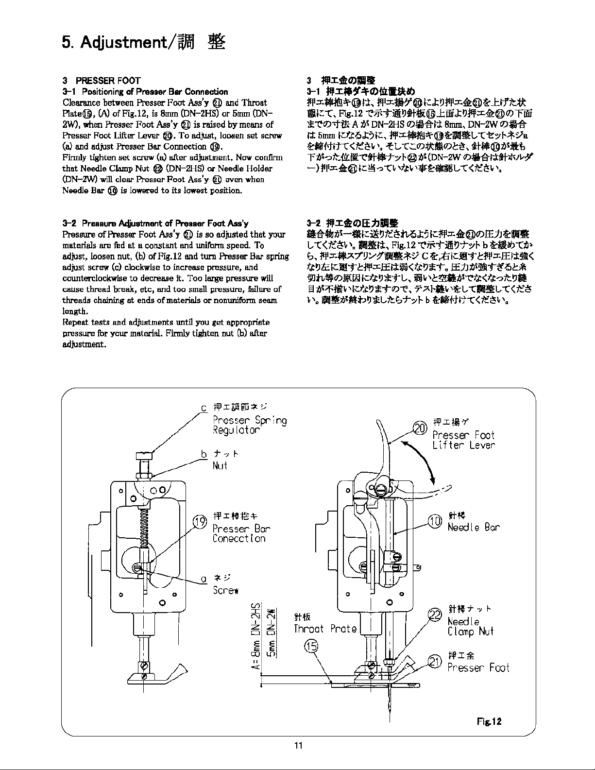
3
PRESSER
FOOT
3-1 Positioning
of
Presser Bar Connection
Clearance between Presser Foot
&s'y
@ and Throat
Plate@,
(A)
ofFig.12,
is 8mm (DN-2HS)
or
5mm (DN-
2W), when
Presser
Foot
&s'y
@ is raised
by
means
of
Presser
Foot
Lifter Lever
@,
To
adjwrt, loosen
set
screw
(a) and adjust Presser Bar Connection
@.
Firmly
tighten
set
screw
(a) u.fter
adjustment.
Now con:finn
that
Needle Clamp Nut @ (DN-2HS)
or
Needle Holder
(DN-2W) will clear Presser
Foot
Ass'y
@ even when
Needle Bar @ is lowered
to
its lowest position.
3-2
Pressure
Acfiustment
of
Presser Foat
Ass'y
Pres8UI'8
of
Presser Foot
&s'y
@ is so adjusted
that
your
materials are fed
at
a constant and unilbnn speed, To
adjust, loosen nut,
(b)
ofFig.12 and turn Presser Bar spring
adjust screw (c) clockwise
to
increase pressure,
o.nd
counterclockwise
to
decrease it. Too large pressure will
ce.use
thread
break,
etc,
and
too
small pressure, failure
of
threads
chaming
at
ends
of
materials
or
nonunil'onn seem
length.
Repeat
tests
o.nd
adjustments until you
get
appropriate
pressure for your material. Firmly tighten nut
(b)
u.fter
adjustment.
• •
0
C
t!¥'.I~fil'.i
~::,;
Presser Spring
Regulator
b
t-
·:,
!---
_,,.-
Nut
a
jfI!fl1]+
Presser
Bar
Conecction
,.
..
,
Screw
"'
I
~
" "
' 'z z
D D
E E
E E
CX)
en
"
~
3
l'i'Illl,0)!11!1
3-1
l'i'IM!lf,,.O)f;iill!il.!tl
jll,o-,,_@l:t,
jll,o!i!!f@ICJ;~jll,o>'l,@/i:Jciflt:1/t
f/iiC"(,
F",g.12
~jf--j";j!~flj!(@JciJiiJ;~j!!,o>'l,@O)riJii
~"e'l1J.f-it.
A
tis
DN-2HS
11)~~1:l
8mm, DN-2W
11)~
ti
5mm
lcflo.l;';IC,
j!!,o_,,_@li:lllll!'l,
-C-1',:,,;l'-Sla
li:lii!Mltt<1':"''',
~L
t.C0):1/t~O)/:~,
fllll>@ll'>i:»
r
l)l-o
ltill:11!-etl-lll>-t",:,
c@lll(DN-2W
0)4!,g-J;tftlls1J.-?"
-)
:jql;r.~@1;:~"':1-n·
,t,ti.-
'*~-l,
-c<tt:~i.-
'o
3-2
jl!Illl,O)EE:llill!I
11,g-1>J,i•-•1c~~1':"'MJ;';Jcjll,o>'l,@O)!EJJ/i:lllll!
\.,
t<1':a'<,,,
l,IJ'il!ti,
Fig.12
~il<i";ii~-t",:,c b
li:lil!"'-Cll>
!',, jll,o$;s:;l'V:.,?11JIJl!;l'-Sl Cli:,;/'i!Cl!!i"
l:jll,o[EJ:t'l!II<
ft~lc
ICJ!!i"
l:jll,o[Et;toli<>\:~£T, !EJJ
Jll'l!lli"l!"
o
I:*
<']tl,$1'0)1Ji(l!jlctt~£i"L, 5Jli,,1:'l!illll~t,<tt-o/t~il
~
Jll"f'j!ii;,1ct,~£TO)~,
'J';s,a,,li:L
-Cl,IJ'il!L
t<1':"<
,
,,
iiili!ll'l<U,~£Llt!',-t",:,c bli:liiMlt-c<te"',
,.
0
• 0
_,,@)
1,:i:11'i
Presser
Foot
~ifter
Lever
..
----;
_-.?
•
It~
i---xl;;oO
Needle
Bar
tt~-t--~
!---
ltl!i
Needle
Throat
Prate
Clamp
Nut
~
flj!.I~
Presser
Fool
Fig.12
11
From the Library of Superior Sewing Machine & Supply LLC
5. Adjustment/wl/)
~
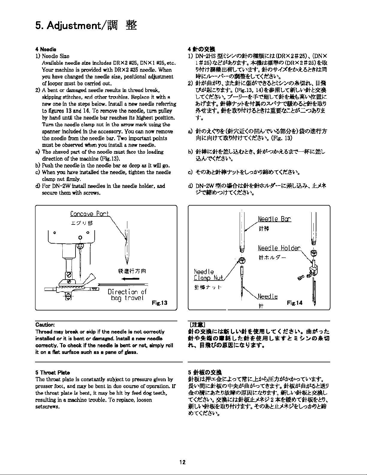
4
Needle
1)
Needle
Size
Available needle size includes
DRX2
#25,
DNX
11125,
etc.
Your
me.chine
is
provided with
DRX2
#25
needle.
When
you have changed the needle size, positional adjustment
oflooper must be carried out.
2) A
bent
or
damaged
needle reaults in thread break,
skipping stitches,
l!lld
other troubles. Replace it with a
new one in
the
steps below. Install a new needle referring
to
figures
13
and
14.
To
remove
the
needle,
tum
pulley
by hand until
the
needle bar reaches its hlghest position.
Tum
the
needle clamp nut in
the
arrow mark using
the
spanner included
in
the
accessory. You can
now
remove
the
needle from
the
needle bar.
Two
important points
must be observed when you install a new needle.
a)
The shaved
part
of
the
needle must face
the
leading
cfuection ofthe machine (Fig.13).
b)
Push
the
needle
in
the
needle
b8l'
88
deep
88
it will
go,
c) When you have installed
the
needle, tighten
the
needle
clamp
nut
Jinnly.
d)
For DN-2W install needles
in
the
needle holder, and
secure them with screws.
0
Caution:
L 7
')
g~
0
0
p r
u
il!
rj
"'"'
-
Directlon
of
bog
travel
Fig.13
Thread may break
or
skip
if
the
needle is
not
correctly
inst.alled
or
it
is
bent
or
damaged. Install a new needle
correctly. To check
if
the
needle is
bent
or
not, simply
roll
it
on a flat
surface
such
as
a
pane
of glass.
5 Throat Plate
The throat plate is constantly subject
to
pressure given by
presser foot, and may
be
bent in due course
of
operation. If
the
throat plate
iB
bent, it may be hit
by
feed dog teeth,
resulting in a machine trouble. To replace, loosen
setscrews.
12
4
ttO>ll:11
1)
DN-2HS ll!sl/1/U)litU)QICl:l:
(DR
X2ii25),
(DN
X
1#
25)
ftl'll'a,~1leT.
-1:l:~'I'"'
(DR
X2#
25)
~Iii<
~t-tltil,llll!t!H!fl-
·n
'1<T. lil"'<t,<;<~,i,;t'!,b~l:tl"I
!tif
1;:,v-,'{-o:>i'ftl&-L-
-C
<
t.:~v
'a
2)
lilll'ilhll'~- >sttlltlcfllll'"<'~'!><sl/:,"'*lllln,
~JR
Vll<ilil::~1leT.
(Fig.13,
14)
~il'li!L-
tffit.,;
•ttc3l:lf!
L,
t<1"~,
'•
7'-V-~"'"('ffi!L,
ttt~Jil:t
;11;,
•irrl!tlC
a,11'1<T.
fl$To/
,~t-t
illl"'"-''-r"t1l!O')'!>l:fl~ll<
~
91-~>sT.
fl~
Iii<
~#It
'!><~l:tll!lft.1:::,,i<=
--.,;,~,s
T.
o)
*"'
;l
<'~~
(tt7':,!i'<"'l!']A,
""'
'-'5$1>}~)
ll!O)Jl!;ff
::I,
leliClelltt!l<~t-lltt<1"~,,.
(Fig.
13)
b)
tt$1ctt~,:tt.,il,t,c~,
ttll<--.,,i,;t
'!>
>s"<'-jif'lcl:tL-
ii,A,
"('<le'~
P.
c) -fcl7)a,ctt$-ro/,~L--oll•~M.,,t<le'~,,.
d)
DN-2W lli!U)jjl1l-i:J:ttttl*1v;f-fc.,L,il,]j., lc-"'f
~Mfbtl"?lt-C<~<'!V'0
r
tf-;t,;1,9"-
Needle
~
Clam
Nut
#'
jj-
~,
t-
·J
r
It
Fig.14
[ltt]
tlO>ll:l!Ucl;UJi
l,
L
'ti
~il/ll
VC
(
t:
.!<
L
'•
ilb
ti<-,
t:
tt~~~O>-Ml-tttt~illlll-*T<~~~a,*~
;,., ll
illtFO>liiil!il
lct.J:
'J
1<1".
5
tt~O>ll:l!I
ttttil:J:Jli',cil,iCJ:
-0
tilt
IC..l:ll•lo/E;/Jlllll•ll•-o
-c,
'1'T.
J;l,
•11!1
lcliltti"'
'P
,ell<
ilb
ll<-o
t~1leT.
ttttill'
ilb
ll''!><il!V
il,U)!lllca,tt
~oJ<:'4'11)
Ji{I!,
1ct,~1<T.
ffit.,;
•ttttic
3l'!!ll-
t <
1"~,'• 'll'lf!ICl:tttl/a-"i<,'2a<~ll!O')ttttti~<~,
ffiL-,otttti~ll<~t-t1t1lei'.
""'"'1c-"i<,'~voll•~,M
bfJ-C<~<'!V'
0

From the Library of Superior Sewing Machine & Supply LLC
5.
Aqjustment/w,'/J :If
6 ADJUSTMENT FOR SINGLE THREAD
SEWING
6-1 Distance between Looper and Needle
Distance between Needle center and Looper point is 5
mm,
when
Looper
is
in the extreme right.
To
obtain this dimension, loosen nut (A).
Looper travel distance should
be
adjusted
Rt
24mm
by
loosening screw (B). (Fig.15)
6-2
Check Height
of
Needle Bar
Adjust the height
of
Needle Bar
to
have distance of
2mm
between Looper point and Needle
Hole
when
Looper point
gets in line with left-side edge ofNeedle in forward and
backward movements. (Fig.16)
5n,n
ltlli</11
~t
Ploi:e
,.,.-··
,..
Thread RetoinGr
t -
---------
Fig.15
6-3
Rxing Throat
f>late
Thread Retainer
Fix
Thread Retalller at Throat Plate, keeping it having
1.1mm
clearance
from
Needle point. When Needle
is
sinking
into the loop, Loope
Guide
helps to spread the
loop
for
succe,11sful
stitchlng. (Fig.17)
6-4
Check of Looper Travel Distance
When
a escape ditch
of
a looper goes along a bottom
of
a
needle board nail, Loosen screw B not
come
into contact a
looper, end please decide a
momentum
of a looper.
~
~·
(9.6mm)
I.
11
I.
Imm
ft!/i/11
Throat
Plat~
Thread
Re\atner
13
6
*llllL
'O)Di!I
6-1
tll::J,--11-0)IUI
JV-
.r{-:@.Jib1&-i.!!L,1t.,!:~, ;t,,-,1~-0J;'c;i:rlNtl~ft;H;J::.
I)
5mm
lcfJ:'.>l:?To/l- A
a1il!~iff!ll!L-
t<1"~,
'•
1V-,.{-l])i'fllJ::l:tJ~
24mm
l.:t.tQJ::?I.:,
..:f~
B
~/l)t
i!il!l/!L-
t<1"~•'•
(Fig.
15)
::UJ\lll!ll!i1!11~>i<L-,.
,,-
,<-UJJ\sil/,lJellill::l!!!lll:l:a'lli
jj,;.f-~1-::f.tQJ:;t.:L,t<tt:~v
'o
6-2
tt•O)-~
,s-,<-UJJ\sil/,la<ttUJtc-Olli!iilc~tti:~.
[mjll~l:tltt
1<UJ
Jc!lilJ:~;o-,<-Q)jsil/,la!
2mm
lcfJ:'.>J:?ICtll!IIUJi!l;
~'1:llff!l/!L,
,<1"~''·
(Fig.
16)
Fig.16
6-3
tll!iJT\O)!lllt-llt
tllliJl\i,l:, tl1r-J:~
1.1mm
lcfJ:'.>J:?
ICtlll,lc->c,,J-L-
t<1"
~i.,,o
tllliJl\i,l:,
tta<,s-::tlcl/ibiblv1'fi<~~-
~
•'llll:ft,.,
J:?ICJ>-::t'l://;;lj''.>tiJ~t:L-llei".
(Flg.17)
6-4
i•-1
<-O);JHIJI
,v-,1'\-0J.::::.~tlii~,
ittiJT\OJ"f~O~~,
,v-,1.::-ti~,
~ttGt,.,J;,ic,j;;,
B
-Hi~,,
,s-,<-UJl!!!IIJ:l:'l:!lc~
-C<tt:'~i.,,o
-
Fig.17
From the Library of Superior Sewing Machine & Supply LLC
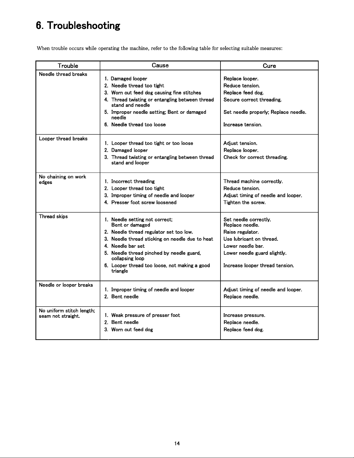
6.
Troubleshooting
When trouble occurs while operating
the
machine, refer
to
the
following table for selecting suitable measures:
Trouble Cause Cure
Needle thread breaks
1.
Damaged looper Replace looper.
2.
Needle thread
too
tight
Reduce tension.
3.
Worn
out
feed dog causing fine
stitches
Replace feed dog.
4.
Thread twisting
or
entangling between thread Secure
correct
threading.
stand and needle
5.
Improper needle setting;
Bent
or
damaged
Set
needle properly; Replace needle.
needle
6.
Needle thread
too
loose Increase tension.
Looper thread breaks
1.
Looper thread
too
tight
or
too
loose
Adjust
tension.
2.
Damaged looper Replace looper.
3.
Thread
twisting
or
entangling between thread Check
for
correct
threading.
stand and looper
No chaining on
work
edges
1.
Incorrect
threading Thread machine correctly.
2.
Looper thread
too
tight
Reduce tension.
3.
Improper timing
of
needle and looper
Adjust
timing
of
needle and looper.
4.
Presser
foot
screw loosened Tighten
the
screw.
Thread skips
1.
Needle setting
not
correct;
Set
needle correctly.
Bent
or
damaged Replace needle.
2.
Needle thread regulator
set
too
low. Raise regulator.
3.
Needle thread sticking on needle due
to
heat Use lubricant
on
thread.
4.
Needle bar
set
Lower needle bar.
5.
Needle thread pinched
by
needle guard, Lower needle guard slightly.
collapsing loop
6.
Looper thread
too
loose,
not
making a good Increase looper thread tension.
triangle
Needle
or
looper breaks
1.
Improper timing
of
needle and looper
Adjust
timing
of
needle and looper.
2.
Bent
needle Replace needle.
No uniform
stitch
length;
seam
not
straight.
1.
Weak pressure
of
presser
foot
Increase pressure.
2.
Bent
needle Replace needle.
3.
Worn
out
feed dog Replace feed dog.
14

From the Library of Superior Sewing Machine & Supply LLC
~7:1
Jl.,P-J~
mi
~ ~
~
J::*
il'--w:J
hi5
1.
Jv-/{-t::~iJ,;bi5o
1v-/{-a-~~T00
2.
J::,%
W!i!-=f
0)
T
:,.,,:,,3:,.,,
iJ,
!Ji
T ~
i5
o
7:,.,,:,,3:,.,,a-!J!J<T.:So
3.
~~~iJ,.$GL.,
--C~
§l
tis~iJ,<fJ:00
~~~a-~~Ti5o
4.
,%:ftti,Git~--c."O)rl!J--c.",%ti,t--:Jti,tcl?,
iJ,i:J~-?tcl'J
,%ti,t--:Jntcl'J, iJ,G~ftv\J::5,%ifilU::tt
Ti5o
;i:i"".:So
5.
itti'-IE'itt::I&l'J#ftGn
--Cv
\ftv
\o
Ji!lti,-?tcl?ffl~L-
if-O)J&
I?
#ftJJti,IE-itti,~l:JiJ,fi~T
.:So
--Cv
\0o
~u
\if-t::~~
Ti5o
6.
J::,%
Mil-=f
0)
7"
:,.,,:,,3:,.,,
ti'-ffiii1//,H
::!J!J
T
~-
i5
o 7:,.,,:,,3:,.,,Bt<T.:So
T*il'--w:lh0
1.
r
,%0)7:,.,,:,,3:,.,,ti'-%ii""~tcl?,
ffil'r#i!t::*ii""~.:So
*
ID!ff-=f
0)7
:,.,,:,,3:,.,,
a-Wlillfllf
T
.:So
2.
Jv-/{-t::~ti,;bi5o
1v-/{-a-~~T00
3.
* ftiJ,G1v-/{-~--c."O)rllJ--c.",%iJ,ti,i:J~-?tcl'J,
t--:J
* ti,t--:Jntcl'J, iJ,G~ftv\J::5,%ifilU::tt
ntcl?Ti5o
;i:i"".:So
@:~iJ,t±\ftv\
1.
,%0)ifill.,1Jti,~t;,ti,-?--Cv
\0o
IEL-<,%a-ifilTo
2.
r
*wm-=f-0)7:,.,,:,,3:,.,,ti'-!lt-r~.:so
r
*wm-=f0)7:,.,,:,,3:,.,,a-!J5.l<-r.:so
3.
it-bv-/{-0)?1-1~:,.,,~-ii'-f'r-?--Cv
\ftv
\0
itbv-/{-0)?7-1~:,.,,::1'a-WlillfllfTi5o
4.
1'Jl.::i:.~O)
11:;,t*
::Jti,*llv--c."v
\;so
¥Jl.::i:.~l1:;,!;;t.::PHilbl'.:li5o
§~V
1.
itti'-IE-itt::I&l?#ftGn
--c1.,
\ttv
\0
if-O)J&
fstftJJti,IE'/tiJ,fiim
Ti5o
if-ti,
Jill
ti,-?tc
I?
ffl
~L,
--Cv
\0o
~u
\if-t::~~
Ti5o
2.
J::,%
wm:tmti,fil;<--eo/
t-
L-
i""~'--c1.,
\00
J::,%
amJ:Wa-J::ff
00
3.
j!P.\O)f;:bl'.),%tisif-(;::<-?--:J<o
*
t::7l!la--fie:ffiTi5o
4.
it~ti,~<--eo/t-~tL--Cv
\0o
it~a-rff.:So
5.
J::,%ti,if-;tf-1F--c."¥Jl~x.--:JftGn--c1v-:1ti,5~<--c."
if-;tf-1Fa-rffi5o
~--c1.,
\ttv
\0
6.
r ,%ti,~-r~---c
J::1.,
\-=-fti~a---:J<Gttv
\0
r
,%0)7:,.,,:,,3:,.,,a-%i<T00
(ti,x_l?
§l
~V)
it
iO'
1ff
hi5
1.
if-~1v-/{-0)?1,1~:,.,,~-ti,~v
\0
it-~1v-/{-0)?1-1~:,.,,
~-a-wli!lfllfT
.:So
1v-/{-iJ,1ffh0
2.
if-ti,
Jill
ti,-?
--Cv
\0o
ita-~~Ti5o
~
§ ~j;o,~;Jil., \
1.
1'Jl.::i:.~J±ti,!J5.Jl.,\o
1'Jl.::i:.~J±a-%i<T.:So
~§ii'-JilliJ,-?--Cv\0
2.
if-ti,
Jill
ti,-?
--c1.,
\;so
ita-3'.t~T.:So
3.
~%}:ti,.$G
L-
--Cv
\0o
~%}:a-~~
Ti5o
15
From the Library of Superior Sewing Machine & Supply LLC
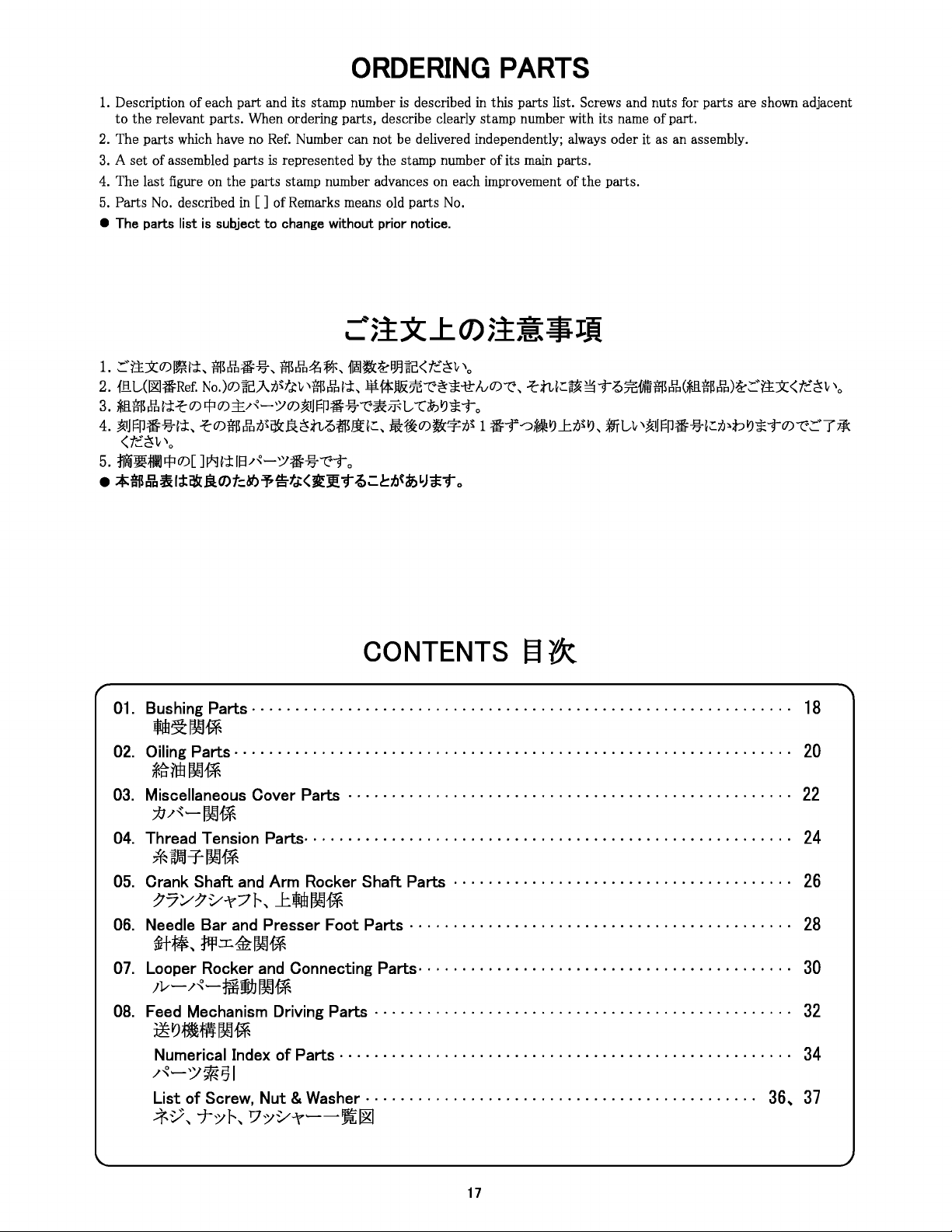
ORDERING
PARTS
1.
Description ofeach part and its stamp number
is
described
in
this parts list. Screws and nuts for parts are shown adjacent
to the relevant parts. When ordering parts, describe clearly stamp number with its name ofpart.
2.
The parts which have
no
Ref.
Number can not be delivered independently;
always
oder it as an assembly.
3.
A set of assembled parts
is
represented by the stamp number of its
main
parts.
4.
The last figure on the parts stamp number advances on each improvement of the parts.
5.
Parts
No.
described
in
[]
of Remarks means old parts
No.
• The parts list
is
subject to change without prior notice.
1.
S:::'r_tj(O)~l'i,
$J1o:ffi:%,
$J1o~~'
11~~1Jnc<t;:~l,,\o
2.
{!::!.L,(~:ffi:Ref.
No.)O)~"cA7'.l~fJ:v
,JmJlr:i
l'i,
l\if*Jl&n--c.>~'*it
NO)--c_\
-tnl;:~
~
T0~1im$J1r:i(*Jl.tf~J1r:i)~
S:::'ttx<t;:~1,,
'o
3.
*lltl'~£1'i-tO)q:iO):±/"~o/O)~iJFP:ffi:%--c.>*ff-L,
tibVJ'*'"to
4.
~IJFP:ffi:%1'i,
-tO)tf~J1oi".J!afcJlt~n01'BJi'.I;:,
:i:ff0)~*7'.l~ 1
:ffi:f'--::i~VJJ::7'.l~VJ,
frU,~iJFP:ffi:%1;:7'.J,:bVJ'*TO)--c.>:.·Tff(
<f;:~l,,
\o
5.
ffi~ffilJq:iO)[
Ji*Jl'ilS/"~o/:ffl:%--c.>To
•
-*'lm~~(;l:ij!Ol©t::clf.>~is-fJ(~Jl!"t
~.:.c!::ti<if>
LJ*"t
o
r
CONTENTS§~
01.
Bushing
Parts · · · · · · · · · · · · · · · · · · · · · · · · · · · · · · · · · · · · · · · · · · · · · · · · · · · · · · · · · · · · · ·
18
,m~~f*
02.
Oiling
Parts · · · · · · · · · · · · · · · · · · · · · · · · · · · · · · · · · · · · · · · · · · · · · · · · · · · · · · · · · · · · · · · ·
20
~ntl~flf-
03. Miscellaneous Cover Parts · · · · · · · · · · · · · · · · · · · · · · · · · · · · · · · · · · · · · · · · · · · · · · · · · · ·
22
7J/{~~f*
04. Thread Tension Parts· · · · · · · · · · · · · · · · · · · · · · · · · · · · · · · · · · · · · · · · · · · · · · · · · · · · · · · ·
24
*
Wi\1-f-
~1*
05. Crank Shaft
and
Arm Rocker Shaft Parts · · · · · · · · · · · · · · · · · · · · · · · · · · · · · · · · · · · · · · ·
26
~7:1/~1/-\"71--,
J:llim~flf-
06. Needle Bar
and
Presser Foot Parts · · · · · · · · · · · · · · · · · · · · · · · · · · · · · · · · · · · · · · · · · · · ·
28
irW,
¥f!::r::.1i2~1*
07. Looper Rocker
and
Connecting Parts· · · · · · · · · · · · · · · · · · · · · · · · · · · · · · · · · · · · · · · · · · ·
30
,i,~
/~~~jb
~1*
08. Feed Mechanism Driving Parts · · · · · · · · · · · · · · · · · · · · · · · · · · · · · · · · · · · · · · · · · · · · · · · ·
32
5~PJIM'¥f
~1*
Numerical Index of Parts · · · · · · · · · · · · · · · · · · · · · · · · · · · · · · · · · · · · · · · · · · · · · · · · · · · ·
34
/~~o/mi31
List of Screw, Nut & Washer · · · · · · · · · · · · · · · · · · · · · · · · · · · · · · · · · · · · · · · · · · · · · 36,
37
.;tV\
-t-:>+,
17o/1/-\"~-1;!£Q
17
Other manuals for DN-2 Series
1
This manual suits for next models
3
Table of contents
Other NLI Sewing Machine manuals


