NLI DHR-6 User manual

NEWLONG INDUSTRIAL CO., LTD.
BAG
SEWING
MACHINE
I
No.1

For Operator Safety
Thank you for purc h a s ing t he N LI
Model DHR-6 Bag Sewing Machine Head.
• This
manual
contains the instructions
and
precautions
for
using
the
Model
DHR-6 Bag Sewing
Machine
Head. Be
sure to read and understand this
manual
before use and
use
the
machine
correctly.
• Keep this manual near
the
sewing machine for easy
reference.
Be
sure to attach this
manual
to the
machine
when
lending
or
transferring
it
to
another person
or
company.
• Please orderthis
manual
from
the nearest NU
office
ifit is
lost.
• The contents
of
this manual are subject
to
change
without
prior notice
for
improvement
and safety purpose.
&Hazard
of
Being
Caught
in the
Machine
• Be careful, when
YoU
insert a bag to
be
closed into
the
sewing
machine, or your fingers
ma:y
be caught
in
the
machine between
the
presser foot and feed
dog.
•A·
Hazardous·
mark
is attached to the
machine.
When
sewing, be sure not
to
touch on
the
machine.
~
Hazard
of
Being Caught in
the
Machine
• A
Needle
Bar and
Needle
Thread Take-Up are
moving
at high speed.
A•
Hazardous"
mark
is attached
to
the
machine. When the
machine
is operation, keep fingers
and yourself
away
from
the
Needle
Bar and
Needle
Thread Take-Up.
:=..::i.-rz:Y!>'°.I•(t*)
DHR-6~
~
1/:Y~;td
_R1,,J:l1"'~tt~11~J1,
:::-~1,"~T,,
•
;:Q)Jtk•tt~•f:t
DHR-6
~ffl~v~Q)Jlk~fl1,
'7i~
~fscffl
J:Q)ttt:•lJltilte.8~.tL-n,
'*To
~fscfflKiH::;:Q)JlkflUM•~~,-ftdWf~<t.::~1,,0
P9~
~+~t,
-CJE.t,<
::'M
<te~v
'o
•
;:Q)
11kffi~
IJJHIJ'1~v~Q),t
J'f
l:::,
1,
,--::i-c1,~1Jffl
1,
,tt.te
lt-o.t;,
{*/fl,
-c<r.:~1,,0
DHR-6
~,u~Jfl~v~Mfl,l:ijl,,
*1tt.J:llill11J!l1tt.J:
;:,Q)
11kffiit~-~,hl;:~L,
"(
<t.::~1,
,,,
e;:Q)Jtk•U~-~~~~tLtt.•1tt.J:=.::i.-o~,I~
cm½1111t•m·i!llfm1:::.::-ttx<te~1,
,,,
•
:.11J
llilffili~
i!Fl'1M~
!Pl
J:
* ft.
1-x~½Q)ft.afJ,
7fit.t
t,
1.:RJ!To:.ttit~t.>*T,,
&-~~-
•
~v~l.:a~t1JA-tot$f±tt:tL-t~11,l:tt~tfll.x~
l::tt)t,S~$l6*Mifctl,t,S~tJ*-t,,
• ~v~•~•'1~l6tt......
-!l~Jli!i-:>-Cll
'*i°"
a
m.o~~v~l;:a•~v~t.,!1,
,.t%:.tt•t-
-c
<~~1,
'-·
.~
~]6~-
• tt-f*~..l:*~fft.J:itH!k~IIJ1,
,-c1,
'*T.,
~vYl;:•';J:~JAtttl...,.-~~Jl~-:>
"Clt
'°*To
~v~t,11JJ1,
,-c1,
,;s2::~1'1tH$~..l:*~ff
l=ti~i*~
i!r--:Sltf~l,
'~<~~1,
,,,
• The instruction manual and parts
list
is subject
to
change
without prior notice.
•
~O)JDl
••
lJ.I.
/I {-•:JIJ
At-lctatBtai
..t
O)f.:NJ~i!t(i:L.1::JIJ!"t
-1,~ciJ(it)
':J;l;"t
0
From the Library of Superior Sewing Machine & Supply LLC
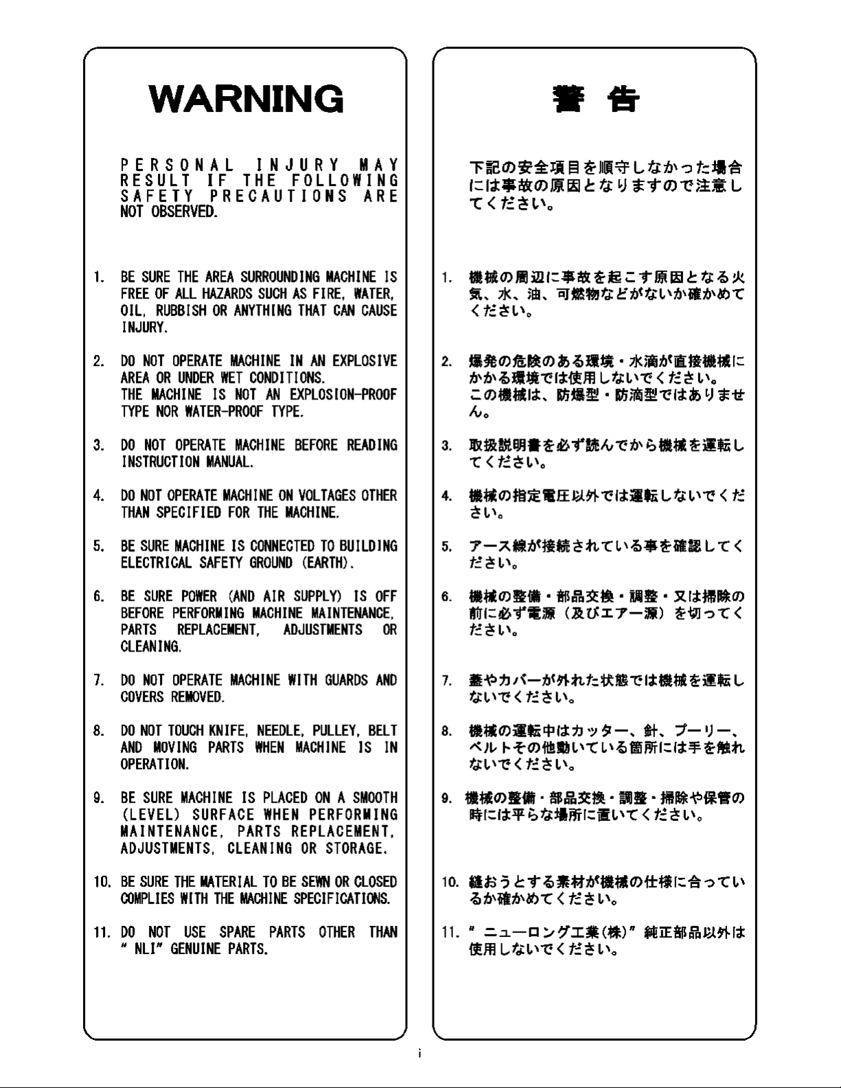
WARNING
PERSONAL
INJURY
MAY
RESULT
IF
THE
FOLLOWING
SAFETY
PRECAUTIONS
ARE
NOT
OBSERVED.
1.
BE
SURE
THE
AREA
SURROUNDING
MACHINE
IS
FREE
OF
ALL
HAZARDS
SUCH
AS
FIRE,
WATER,
OIL,
RUBBISH
OR
ANYTHING
THAT
CAN
CAUSE
INJURY.
2.
DO
NOT
OPERATE
MACHINE
IN
AN
EXPLOSIVE
AREA
OR
UNDER
WET
CONDITIONS.
THE
MACHINE
IS
NOT
AN
EXPLOSION-PROOF
TYPE
NOR
WATER-PROOF
TYPE.
3.
DO
NOT
OPERATE
MACHINE
BEFORE
READING
INSTRUCTION
MANUAL.
4.
DO
NOT
OPERATE
MACHINE
ON
VOLTAGES
OTHER
THAN
SPECIFIED
FOR
THE
MACHINE.
5.
BE
SURE
MACHINE
IS
CONNECTED
TO
BUILDING
ELECTRICAL
SAFETY
GROUND
(EARTH).
6.
BE
SURE
POWER
(AND
A
IR
SUPPLY)
IS
OFF
BEFORE
PERFORMING
MACHINE
MAINTENANCE,
PARTS
REPLACEMENT,
ADJUSTMENTS
OR
CLEANING.
7.
DO
NOT
OPERATE
MACHINE
WITH
GUARDS
AND
COVERS
REMOVED.
8.
DO
NOT
TOUCH
KNIFE,
NEEDLE,
PULLEY,
BELT
AND
MOVING
PARTS
WHEN
MACH
I
NE
IS
IN
OPERATION.
9.
BE
SURE
MACHINE
IS
PLACED
ON
A
SMOOTH
(LEVEL)
SURFACE
WHEN
PERFORMING
MAINTENANCE,
PARTS
REPLACEMENT,
ADJUSTMENTS,
CLEANING
OR
STORAGE.
10.
BE
SURE
THE
MATERIAL
TO
BE
SEWN
OR
CLOSED
COMPLIES
WITH
THE
MACHINE
SPECIFICATIONS.
11.
DO
NOT
USE
SPARE
PARTS
OTHER
THAN
"
NL!"
GENUINE
PARTS.
••
~~©~~~§~~~L~~?~~~
l:::l~t:-Ml:©ffli~
c.
t.;.
")
a::"t©~~~
L
L <
t::
~
I,
\0
1.
•
~
0)
)!] ill
I=
$
i!it
~
~
.:.
"t"
mt
~
c.
t.;
7a>
!k
~..
JJ<..
im..
i:iJ:I!~
t.;
ct.it~
1.
,t.i,.fitt.i,cY)
t
(f;:~l,\o
2.
-~O)ffi;l!iO)
if>
7a>•:tl
• ll<m!it.iti~Ji.~I=
f.1,f.1,7a>.±Jl--c:l;t-ftffl
L,tJl,\""(:
<t::~
(,\0
.:.0)-~l;t
..
Rn-~.
Rnm!i~--C:l;tN.,
")
'tit
lvo
3.
Jljif&mBJ.lif~~"(McA,--c:f.l,
1:,--~jifii
L
t ( f;:~
l,\o
4. -~O)}~JE'.fflff
J~H'l-
--c:l;tjifii
Lt.;
I.'
--c:
<
t::
~l,\o
5.
7-7..~t.it~*.,'c~ht1.,7a>$~.fit~
Lt<
f;:~l,\o
6.
•~O)~iiffi
• !B~3'.cm.
ru11~
• ~11:m~O)
AAl=~"fffl;Ji
C.&ttI7-;Ji)
~~-:it<
f;:~l,\o
7.
ii~1JJ{-t.i<~nt=~~--c:l;t·~~jifii
L
fJl,\""(:( f;:~l,\o
8.
..O)jifji
cp
l;j:
7.J
'~
5(
-
,.
$t
._
-;/-
1)
-
._
~Ji.,
"-t
O)·fttt1.11.,
t
1.
,7a,
~rffl=
11-¥
~Mn
fJl,\""(:( f;:~l,\o
9.
•~O)•iiffi·!B~3'.cm-~•-:m~~~~O)
~1=11:qr
i;
t.;:t1rffl=i'fi1.
't
<
t::
~
1.
,0
10.
ifl;Js-3
c.
"t"
7a>~*1t.it-~O)f±~l=-€.--:i t
(,\
7a,
f.1,-fitf.1,cY)
t <
t::
~
I,
\0
11.
"=-.:i.-Cl/~I~(*l)"
til!iE!B~~~l;t
ilffl
Lt.;
I.'
1: <
t::
~
I.
'o
From the Library of Superior Sewing Machine & Supply LLC

Identifying and Ordering Parts
Cautions When Using the Machine
Maintenance
Where the construction permits, each part
is
stamped with
its part number. On
all
orders, please include part number,
part name
and
model name
of
machine.
Safety Rules
To prevent personal injury:
•
All
power sources to the machine must be turned
off
before threading, oiling, adjusting or replacing parts.
•
All
cover and guards must be
in
position before operating
machine.
•
Do
not tamper with safety cover, guards, etc.,
while
machine
is
in
operation.
Safety Precautions
1)
Always
turn power off before threading, oiling, and
adjusting the machine or replacing parts.
2)
Wear safety glasses.
3)
Make
sure, before starting the machine, that
all
covers
and shields are
in
place and closed.
4)
Do
not touch on the machine when it
is
run.
5)
Turn power
off
and make sure the cutter does not operate
before you put your fingers under the cutter blades and
the needles to adjust.
6)
Do
not touch on the machine when it
is
run.
• Please keep
in
mind
to handle the machine carefully and to
maintain the machine
in
good condition.
• Thread fuzz or dust must be cleaned
with
air or brush on
throat plate,
in
the groove of feed dog or around looper
after the day's work.
• Wipe the area easy to rust with
oil
cloth.
• Check the machine for loose screws and tighten them, if
any, once a month.
• Good
maintenance
will
prolong
the
machine life.
ii
•
:=.=1-
-o:.,,~-I~
(~)
~OO~~ffl·~~ml;:.f';:!:DHR-6
(J)
itililE
ti%fb
:a:-~-Om
L,
--c
:Jo~
~To
•
:::·r±.x(J)~i-;:1:,
/"-o/!J?-J--(1)/"-o/*%,1:~~--c:-:::·mjf-
<tt~i.
\0
•*fflL~~OO~~&O*ffl~(J)~-~~-~~-~
(J){i:!!l!f-0mftc1::--C:-/g¥~
f;:.
<v,~_.g.l'i,
:Jo
J'l
v
'LITv
'tctc~
~L,tc:=.=1--01/~-I~(~)~OO~~Pfr·~mm1;:.~~m
<tt~v
'o
j\!;j~(J)~.
~fl~,
~~:ffi:%, ~1/1/.lm®~,
~
1/1/:ffi:%:a:-:::·mjf-<tc~v
'~T
J:5:Jol»lv
'v
'fcL,~"t"o
1>
~~~~
•*mn(J),l:~(J)*ifilL,, *(1)3'.t~.
*1'i71:!l.
w.Bl!f.
®&3'.t~.
f*"'f,¢.e~f'F~(J)irrr1;:.~,--rt7JJ:a:-m-::i--c<tt~
v'o
2)
W!Bl!ffp~(J),l:~l'i'ti:V:JJ
*(J)*ffl
:a:-:Jo"t"T~
L,~"t"
o
4)
.iJ
/'{-ftc1::;vt1¥J~-::i
--Cv
,Q;:_,1::a:-~~
L,
--c;v,G~~L,
--c
<
tc~v\o
5)*(J)-fl;:.-¥:a:-AnQ,1:~1'i,
~,--rt7JJ:a:-m-::i--c<tt~i.
'o
f~~W!ffl!f
(J)
,1:~1'i,
~,
--rt7JJ:a:-m
~~1/:.,,;vtllJ;v,ftv
,;:_,1:
:a:-~~L,
--c;v,Gf'F~:a:-rr-::i--c<tc~v'o
• ~1/1/llli'tf~l'i~!Wft1J,~ft$
Jl1=1;v>G/±:l*L;vt-::i--Cv
'~To
r±.~~<
I&Wl5
,1:,1:t
1;:.
~
1;:.l!f-Om
1;:.,tA1Ht--c
<
tt~v
'o
• -
f::l
(J)fp~;vt~TL,~L,tcG,
*fi(J)L,
~!J~(J)r#(J)
~-
1v-/"-(J)~:b~1;:.~~-::itdi::.~~l'i~hv'l;:.I&~
~v'--C<tc~v\o
• -¥Ah(!).&L,~U'i~~(J)~~f;:.J&9L,~T(J)--c:':::·r±.~
<tc~v\o
From the Library of Superior Sewing Machine & Supply LLC
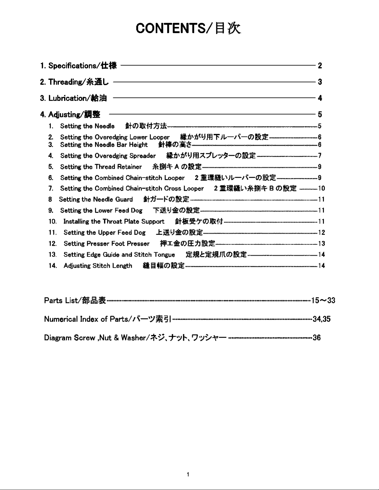
CONTENTS/
~
{X
1.
Specifications/fr~
--------------------
2
2.
Threading/*ill,
3
3.
Lubrication/~nb 4
4.
A<tjusting/iffljg
-------------------
5
1.
Setting
the
Needle
~fO)Joli.tn)!-----------------5
2.
Setting
the
Overedging Lower Looper fitJ,tJ<LJffl""FJL,-1{-0)~;E'. 6
3.
Setting
the
Needle Bar Height
~t,$0)
~
~
6
4.
Setting
the
Overedging Spreader
fiti,tJ<LJffiA:1v•;,1t-O)~JE'.-------7
5.
Setting
the
Thread Retainer
~H.!JI]=\=-
A
O)~JE'.-------------9
6.
Setting
the
Combined Chain-stitch Looper 2
m:J1a1,,Jt.,-1~-0)~JE'.-----9
7.
Setting
the
Combined Chain-stitch Cross Looper 2 mJ1a1,
'~H.IJI]=\=-
B
O)~;E'.
................
10
8 Setting
the
Needle Guard
~t:fl-~'O)~;E'.--------------11
9.
Setting
the
Lower Feed
Dog
""F~LJ~O)~JE'.-------------11
10.
Installing
the
Throat Plate Support
~HJ.i~70)1fXi-t-----------11
11.
Setting
the
Upper Feed
Dog
..t~
LJ~O)~;E'.
12
12.
Setting
Presser
Foot
Presser
:j:l:jl.I
~O)
ff.jJ
~;E
13
13.
Setting Edge Guide and Stitch Tongue
JE'.:ml=JE'.:mffiO)~;E'.
14
14.
Adjusting Stitch Length a
El
~;O)~;E'.
14
Parts
List/$~~····························································································································15,.,.,,,.,33
Numerical
Index
of
Parts/
I
~-'-Y~
S1
·····················································································34,35
Diagram
Screw ,Nut &
Washer/*~
..
T'.:11--
..
r'J':J~-'t'-
···················································36
From the Library of Superior Sewing Machine & Supply LLC
Table of contents
Other NLI Sewing Machine manuals


