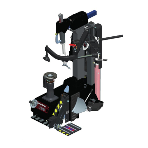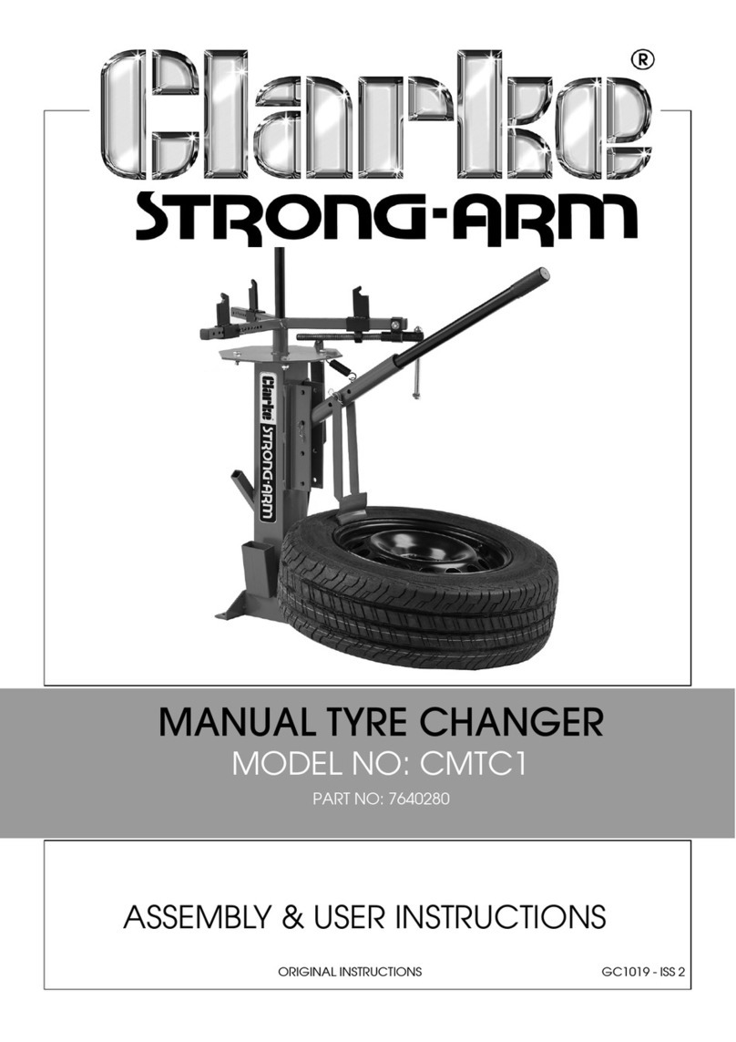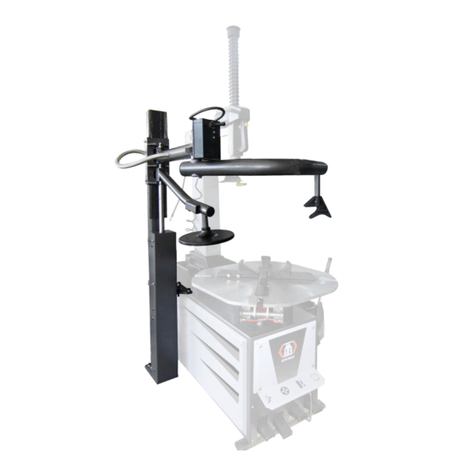
Machine Parts
Stand Post
Stand Bottom Plate
Stand Top Plate
Frame Assembly
Back Post w/Swivel Tee Pre-Installed
Stop Collar (2)
Clevis Collar
Bead Breaker Arm
Bead Breaker "Tee"
Upper Slide Arm
Center Post
Dog Block (2)
Cam Block
Mount/Demount Bar
M/D Bar Handle
Assembly Parts
5/16" x 5/16" set screw (8)
1/2" x 1" Hex bolt (3)
1/2" Flat Washer (3)
5/16" x 3/4" Flat Socket Head Screw (8)
3" Carriage Bolt and Locking Knob
5/16" Flat Washer
5/16" x 3/4" Shoulder Bolt (1)
5/16" x 5/8" Shoulder Bolt (1)
1/4" Nylock Nut (1)
Center Post Knob (1)
5/16" x 1 /2" Flat Socket Head Screw (12)
Replacement Demount Tip (Part#: DT3B)
3/16" Allen Wrench (in stand box)
5/32" Allen Wrench (with M/D Handle)
5/16" x 1 /4" set screw
0
'
i i ! i(x4)
Classic Model Tire Changer Assembly Instructions**
Changer Placement: It is recommended assembling the tire changer before mounting to the floor so the user will better understand the space needed
for the changer and changer tools.
STEP 1 Attach Stand Base (B) and Stand Top (C) to Stand Post (A) Using (8) Screws (S). Make sure all threads of all 4 bolts are started before tightening.
STEP 2 Attach 3 frame arms (D) using 2 "Y-plates", fastening with 6 screws (Z) on top and bottom.
STEP 3 Attach Frame Assembly (D) to the Stand Assembly, using (3) 1/2" hex bolts (Q) and washers (R).
STEP 4 Secure one Stop Collar (F) onto the Back Post (E), approximately 1/8" below Swivel Tee by tightening 2 set screws (P).
STEP 5 Slide Clevis Collar (G) onto Back Post (E) and leave loose. This part needs to spin freely.
STEP 6 Secure the second Stop Collar (F) onto Back Post (E) 1 /8" below Clevis Collar (G) by tightening 2 set screws (P)
STEP 7 Slide Back Post (E) into the top of the Frame (D) so that it extends approximately 6" below rear frame arm collar. Tighten (4) set screws (P).
STEP 8 Attach Bead Breaker Arm (H) to the Clevis Collar (G) using the 3/4" shoulder bolt (V).
STEP 9 Attach Bead Breaker "Tee" (I) to the Bead Breaker Arm (H) using the 3/4" shoulder bolt (W) and one Nylock nut (X).
STEP 10 Insert Upper Arm (J) in the opening of the Swivel Tee as shown with the larges holes at the front and oriented up and down. Tighten the
Locking Knob (T) to secure the slide arm in position. Do not over-tighten. The upper arm should swing side-to-side freely at this time.
STEP 11 Insert the Center Post (K) into the hole on the end of the Upper Arm (J). Hold in position using the Center Post Knob (Y) on the side. Adjust the
Center post height according to the wheel and tire combination you are changing.
STEP 12 See separate instructions included with Mount/Demount Bar for assembly and usage . See website for complete tire changing instructions and videos.
**Parts, labels, names, drawings, pricing and availability are subject to change without notice. See website for most current information.
REV. 12/2017CA

