ATH-Heinl A31 User manual

® Copyright by ATH-Heinl GmbH & Co. KG, 2014, All rights reserved /Misprint and technical changes reserved / Issue: 08/2013
1
USER´S MANUAL
A
AT
TH
H
A
A3
31
1
A
AT
TH
H
A
A3
34
4

® Copyright by ATH-Heinl GmbH & Co. KG, 2014, All rights reserved /Misprint and technical changes reserved / Issue: 08/2013
2
CONTENT
INTRODUCTION ....................................................................................................................................................................3
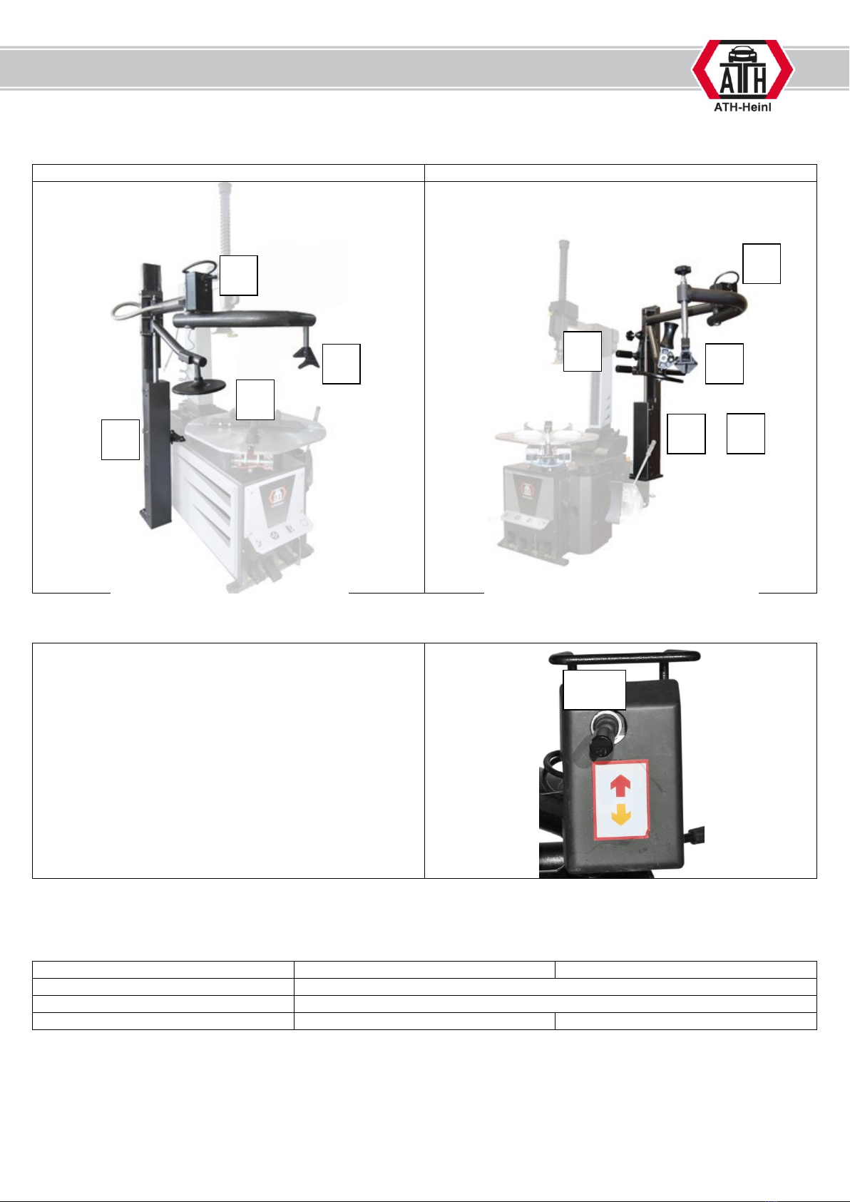
Description of assist arm ....................................................................................................................................................4
Technical data ....................................................................................................................................................................4
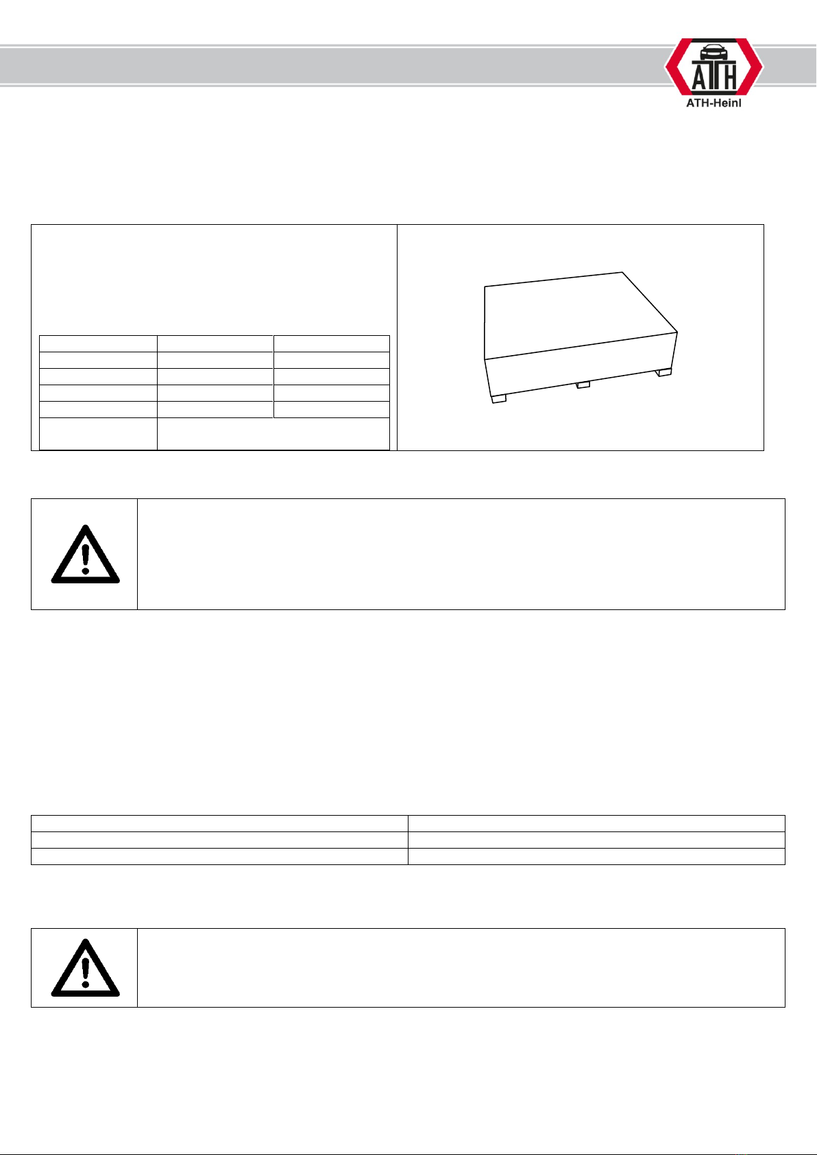
Transport and storage ........................................................................................................................................................5
Unpacking of machine ........................................................................................................................................................5
Standort ..............................................................................................................................................................................5
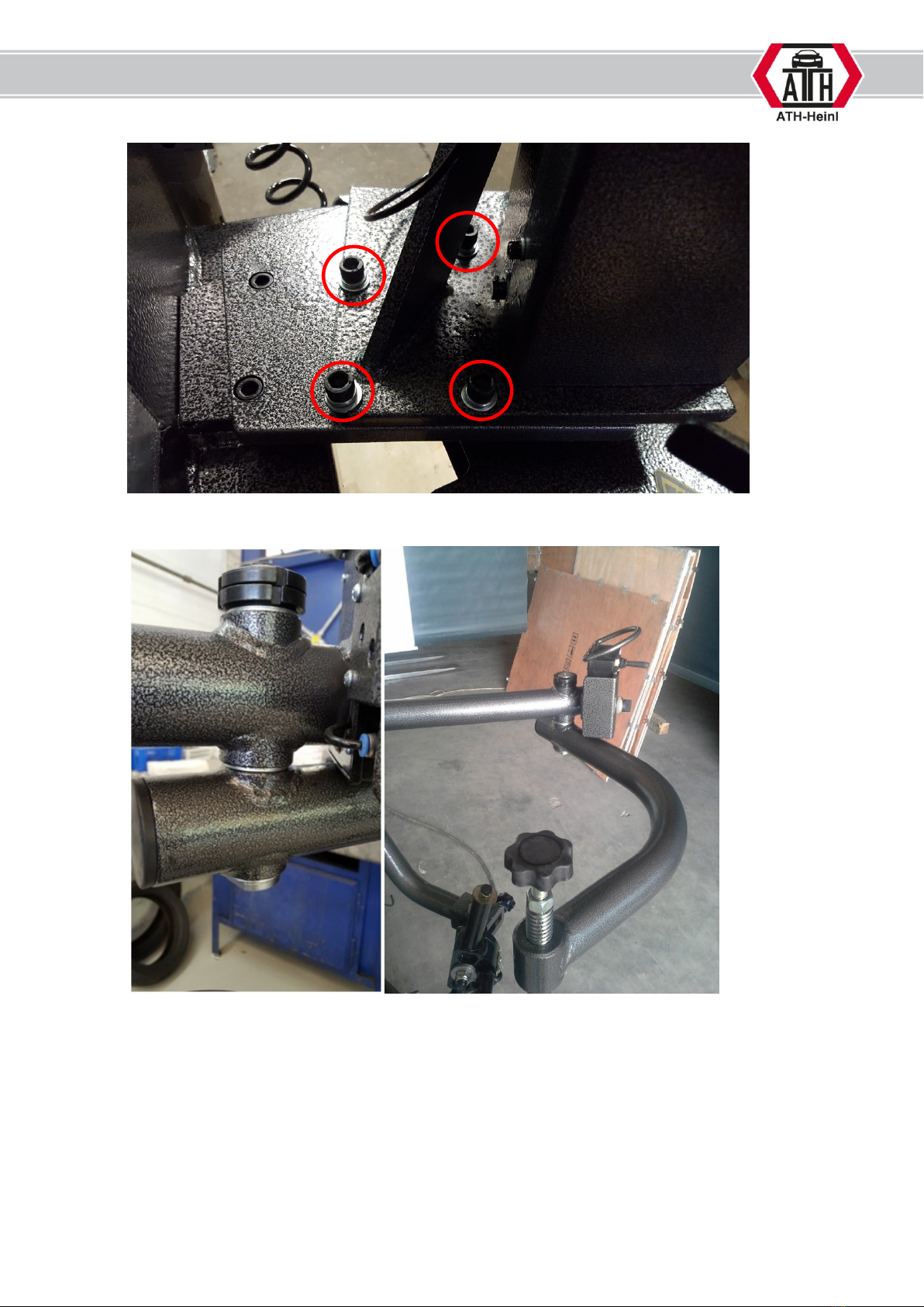
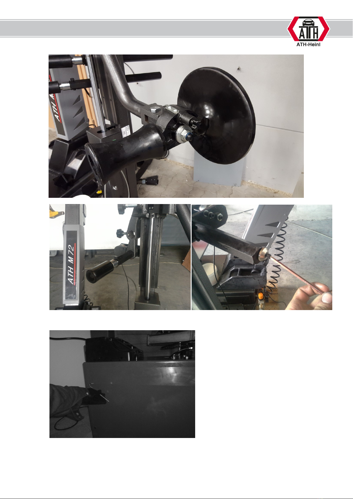
Fixing ..................................................................................................................................................................................5
OPERATION.........................................................................................................................................................................11
Safty instructions ..............................................................................................................................................................11
Use ...................................................................................................................................................................................13
MAINTENANCE ...................................................................................................................................................................16
Troubleshooting ................................................................................................................................................................16
Maintenance instruction....................................................................................................................................................16
KONFIRMITÄTSERKLÄRUNG............................................................................................................................................17
SPARE PARTS ....................................................................................................................................................................18
Spare part list A31 ............................................................................................................................................................20
Exploded drawing A34......................................................................................................................................................22
Spare part list A34 ............................................................................................................................................................23
ATTACHEMENT...................................................................................................................................................................26
Pneumatic sceme .............................................................................................................................................................26
GARANTYKARD..................................................................................................................................................................27
NOTES..................................................................................................................................................................................29

® Copyright by ATH-Heinl GmbH & Co. KG, 2014, All rights reserved /Misprint and technical changes reserved / Issue: 08/2013
3
INTRODUCTION
THIS MANUAL IS AN INHERENT PART OF THE MACHINE.
IT MUST BE READ AND UNDERSTOOD FROM THE OPERATOR.
THERE IS NO RESPONSIBILITY FOR DAMAGES, WHICH ARE RESULTING FROM NON-
OBSERVANCE OF THIS MANUAL OR THE GUILTY SAFETY REGULATIONS.
ATTENTION: Follow the instructions to avoid injuries or damages.
TIP: Gives further informations to the functions and tips for using the machine efficiently.
Protective clothes must be worn for all works on the described machine.
Name plate:
Note all informations regarding the tire changer into the following gaps.
It is forbidden to remove the name plate from the tire changer.

® Copyright by ATH-Heinl GmbH & Co. KG, 2014, All rights reserved /Misprint and technical changes reserved / Issue: 08/2013
4
Description of assist arm
A31
A34
1. Double acting pneumatic Cylinder
2. Beadholder
3. Control unit
Operation
3.1 Handle to control the up and down movement of the
bead holder, tire support disc and bead roller (only by A34).
4. Tire support disc
5. Bead roller
Technical data
Type
A31
A34
Working pressur
8-10 bar
Noise level
<80 dB(A)
Weight
80 kg
100 kg
1
3
2
4
1
3
2
4
5
3.1

® Copyright by ATH-Heinl GmbH & Co. KG, 2014, All rights reserved /Misprint and technical changes reserved / Issue: 08/2013
5
INSTALLATION
The machine should be installed only by authorized personal according to the manual.
Transport and storage
Always use suitable means for transporting and
positioning the machine and keep attention to the gravity
center of the machine.
The machine should only be transported with the original
packing.
Type
A31
A34
Lenght
1.550 mm
1.220 mm
Width
820 mm
1050 mm
Height
310 mm
340 mm
Weight
90
110 kg
Storage
temperature
0°C ~+50 °C
Unpacking of machine
Remove the upper cover of the carton and make sure that there were no damages during the transport.
Remove the safety bolts to get the machine from the pallet.
For taking the machine from the pallet use a suitable means (eventually with sling).
The packing material of the machine should be stored carefully.
Keep the packing material away from children as it could be dangerous for them.
Standort
The machine should be kept away from flammable and explosive materials as well as from solar radiation and intensive
light. The machine should also be installed in a well-ventilated place.
The tire changer must be placed on a concrete floor or similar solid flooring.
When selecting the place of installation, besides the soil condition also the guidelines and instructions of the accident
prevention regulations and workplace regulations must be observed.
It is not allowed to install the machine outside, but only inside, as the machine has no corresponding safety provisions (IP-
protection, zinc coated and so on)
Temperature
0-50 °C
Air humidity
10-90% (ohne Kondensation)
Sea level
≤2000m
Fixing
Here, the general and local regulations must be observed. Therefore this step must be performed only
by an expert.
Pay attention to the correct current supply. (see technical data).
1. Preparation:
a. Disconnect the tire changer from any electrical or pneumatical connection
b. Check the correct fixing of tire changer

® Copyright by ATH-Heinl GmbH & Co. KG, 2014, All rights reserved /Misprint and technical changes reserved / Issue: 08/2013
6
c. Remove all parts from the installation area (f.e. grease bucket)
d. Put the support bar under the connection point
2. Add the main post:
a. Fix the main plate on the maschine.
b. Fix the post oft he assist arm on the main plate.

® Copyright by ATH-Heinl GmbH & Co. KG, 2014, All rights reserved /Misprint and technical changes reserved / Issue: 08/2013
7
3. Add arms
a. Mount the bend arm on the arm where control unit is add
b. Add the bead roller and tire support disk on the swivel part

® Copyright by ATH-Heinl GmbH & Co. KG, 2014, All rights reserved /Misprint and technical changes reserved / Issue: 08/2013
8
c. Add both bead roller arms and secure them
4. Pneumatic connection
a. Remove the side wall
b. Cut the pneumatic line and add the T-connector. Now you can put the airline of the assist arm through the
hole in the machine and connect to the T-piece.

® Copyright by ATH-Heinl GmbH & Co. KG, 2014, All rights reserved /Misprint and technical changes reserved / Issue: 08/2013
9
c. Now you can install the side wall again
5. Final step´s
a. Check the correct position of the sliding pieces
If needed, the distance can adjust as following:

® Copyright by ATH-Heinl GmbH & Co. KG, 2014, All rights reserved /Misprint and technical changes reserved / Issue: 08/2013
10
Loose the fixing nut on the studs (A & B). The clearance can be adjusting by screw in or out the studs. To
finish the adjustment, the nuts should be fixed again.
By long term of using the clearance have to adjust again, to secure the precise movement of arms.
b. Before starting the operation all bolts, nuts and connections have tob e checked.
A
B

® Copyright by ATH-Heinl GmbH & Co. KG, 2014, All rights reserved /Misprint and technical changes reserved / Issue: 08/2013
11
OPERATION
Safty instructions
THE TIRE CHANGER IS ONLY ALLOWED TO BE OPERATED BY SKILLED AND TRAINED TECHNICIANS OVER 18
YEARS.
BEFORE MOUNTING OR DEMOUNTING CHECK ALL COMPONENTS. THOSE MUST NOT HAVE ANY DAMAGES.
THE MACHINE IS ONLY TO BE USED ACCORDING TO ITS INTENDED AND SPECIFIED USE.
FOR A CORRECT MOUNTING OF THE RIMS IT IS PROBABLY NECESSARY TO USE A CORRESPONDING
ACCESSORY (e.g. PLASTIC PROTECCTION FOR CLAMPING JAWS, MOUNTING HEAD AND MOUNTING LEVER
OR MOTORCYCLE ACCESSORY).
DO ALWAYS TAKE THE INTENDED MATERIAL, e.g. THE CORRECT TIRE DIMENSION, SUITABLE VALVES OR THE
CORRECT MOUNTING GREASE.
BEFORE MOUNTING OR DEMOUNTING CHECK ALL COMPONENTS. THOSE MUST NOT HAVE ANY DAMAGES.
PAY ATTENTION TO POSSIBLE SPECIAL MOUNTING OR DEMOUNTING INSTRUCTIONS OF THE TIRE
MANUFACTURER.
DURING OPERATION PAY ATTENTION TO DANGEROUS SITUATIONS. IF THERE ARE ANY DANGERS SWITCH
OFF THE MACHINE IMMEDIATELY, DISCONNECT THE CURRENT SUPPLY AND THE AIR SUPPLY.
FOLLOWING CONTACT YOUR DISTRIBUTOR.
DURING MOUNTING OR DEMOUNTING OR INFLATING OF TIRES OBSERVE STRICTLY THE GUIDELINES OF WDK
(TRADE ASSOCIATION OF THE GERMAN RUBBER INDUSTRY).
MOUNTING OR DEMOUNTING OF TIRES WHICH ARE OLDER THAN 30 YEARS CAN CAUSE ACCIDENTS OR
DAMAGES.
Pay attention to possible shearing points on the tire changer.
Be careful while filling tires - damaged or dirty tires can cause serious injuries.
Moving parts of the machine can catch loose clothing, long hairs or jewelry.
ALL WARNING SYMBOLS MUST BE ALWAYS READABLE; THEY MUST BE REPLACED IMMEDIATELY IN CASE OF
ANY DAMAGE ON IT.

® Copyright by ATH-Heinl GmbH & Co. KG, 2014, All rights reserved /Misprint and technical changes reserved / Issue: 08/2013
12
Assist arm
Risks for human and environment
Bursting tires, balancing weights or rim parts which blow away can cause serious
injuries.
By abrasion of brake linings harmful dust will be released.
Precautions and rules of conduct
Do only use impact screw drivers which are not blowing onto the rim.
To avoid dust, only clean rims and tires wet; if possible use washer for tires.
Remove dust on the brake drums with exhausting bell in connection with a suitable
industrial vacuum cleaner. Use equipment of Category U for nonasbestos dust and
equipment of Category K1 for asbestos-containing dust.
Do only use faultless rims. By flat mould rims, which are sticked together by spot
welding, the seam resistance has to be checked.
Faulty tires have to be made unusable.
While inflating the tire position a safety device for collecting parts which blow away.
Keep persons away from the danger zone.
On tire changers with vertical positioned tires the working with heavy weight tires
(e.g. earth mover tire molds) must be made by 2 persons.
At tires with a diameter > 1,4 m or a weight > 200 kg safety devices against falling
over must be used.
The inflating of tires must be observed and the maximum mounting pressures are
not allowed to exceed.
Behaviour in case of error
Detected errors have to be reported to the responsible person.
First Aid
Emergency call:
Keep in mind in case of an accident not only to save the injured person and to
render first aid but also to secure the scene of accident.
Report every accident immediately to the responsible person.
Place of first aid kit and first aid book:___________________
Record all information in the first aid book.
Maintenance, Disposal
Reparations are only allowed to be made by the after sales service of the
manufacturer.

® Copyright by ATH-Heinl GmbH & Co. KG, 2014, All rights reserved /Misprint and technical changes reserved / Issue: 08/2013
13
Use
The product is a helping device for mount and demount very stiff tires.
All regulations of manufacturers of rim and tire have to be consider.
1. Demount
a. Breake the bead oft he tire.
b. Adjust the clamping claws to the size of the rime (f.e. by 20“ rim, adjust to 21“)
c. Take the additional cone adaptor and place them tot he midhole oft he rim. Now you can push the rim down
to clamp the rim more easily
d. Place the bead roller and the bead holder by the edge of the rim. For placing the crowbar, you have to push
down the bead of the rim. After placing the crowbar, the arms can be remove from the wheel.

® Copyright by ATH-Heinl GmbH & Co. KG, 2014, All rights reserved /Misprint and technical changes reserved / Issue: 08/2013
14
e. Now the bead holder has to be placed opposite of the duck head, so the leverage of the crowbar is more
easily. Furthermore, it avoids damage on the wheel.
If the leverage is still too heavily, the tire can be pressed down on 3, 6 & 12 o´clock position.
f. As soon as you have levered the wheel, you can remove the bead holder and start to rotating in clockwise
direction.
g. Lift up the tire and demount the second bead.
If the tire is stuck in the rim bead, you can lose it by using the tire support disk.
Regarding the turning of the wheel the disc will moving.
By some wheels it´s also possible to use only the bead roller o demount the second bead.
Here you can mount as following:
oPlace the bead roll under the bead of the tire. Pay attention to have a small gap between the rim and the
bead roller. After this you can push up the bead above the edge of the rim.

® Copyright by ATH-Heinl GmbH & Co. KG, 2014, All rights reserved /Misprint and technical changes reserved / Issue: 08/2013
15
2. Mount
a. Put grease on rim and wheel.
b. Mount the downside bead as usual.
The bead holder can assist you in this issue.
c. By mounting the upside bead you have to push the wheel with both bead roller and the bead holder under the
duck head, here you have to push the wheel on the height of the first gap inside the rim. Start with the
rotation of the wheel.

® Copyright by ATH-Heinl GmbH & Co. KG, 2014, All rights reserved /Misprint and technical changes reserved / Issue: 08/2013
16
MAINTENANCE
TO GUARANTEE A SAFE OPERTION OF THE MACHINE THE OPERATOR IS OBLIGED TO MAINTAIN THE
MACHINE REGULARLY.
ONLY AUTHORIZED SERVICE PARTNERS ARE ALLOWED TO MAKE REPARATION WORKS. THE CUSTOMER IS
ONLY ALLOWED TO MAKE THIS AFTER CONSULTING THE MANUFACTURER.
For maintenance and reparation works the machine must be disconnected from ALL power supply
(main switch off, mains plug disconnected). There has to be made precautions for a reconnection by
accident.
For bleeding the complete compressed air out of the machine press the pedal for the bead breaker
several times.
Works on the electrical part of the machine respectively on the supply lines are only allowed to be
done by technicians respectively electrically skilled persons.
Troubleshooting
Error
Reason
Solution
No up or down movement
No compressed air
Check pneumatic supply
Leaking air hose
Seal or replace the air hose
Maintenance instruction
Time:
Part:
To-Do:
Weekly
Arm of bead holder
Clean and grease
Monthly
Joints
Grease
Sliding pieces
Grease
Notice: The shown scendule is for a normal use. We recommend to make the maintenance everytime before operating.

® Copyright by ATH-Heinl GmbH & Co. KG, 2014, All rights reserved /Misprint and technical changes reserved / Issue: 08/2013
17
KONFIRMITÄTSERKLÄRUNG
Seriennummer / Serial number:
Konformitätserklärung
Declaration of conformity
Déclaration de conformité
Declaración de conformidad
Für / for / pour / para
Typ / Type / Type / Tipo
Hilfsmontagearm
Assist arm
Bras additionnel de montage
Brazo prensa-levanta talón neumático
ATH A31
ATH A34
Wurden folgende einschlägige Bestimmungen beachtet
The following EG-directives are considered
Les Directives suivantes de l’Union européenne ont été
respectées
Los siguientes directivas pertinentes de la Unión Europa
fuen cumplido
98/37/CEE - 91/368/CEE - 93/68/CEE - 89/336/CEE -
86/217/CEE
27/404/CEE - 73/23/CEE - EN 91/263/CEE - EN
92/31/CEE
EN 93/97/CEE - EN 98/13/CEE D.P.R. nr. 459 DEL
24/07/96
Folgende harmonisierten Normen und Vorschriften wurden
eingehalten
The following harmonized standards are applied
Les normes harmonisées suivantes ont été appliquées
Los siguientes normas y reglamentos armonizados fuen
cumplido
EN 292 - EN 60204-1 - EN 50081-1 - EN 50082-1
Hersteller
Manufacturer
Fabricant
Fabricante
ATH-Heinl GmbH &Co. KG
Kauerhofer Straße 2
D-92237 Sulzbach-Rosenberg
Germany
Hiermit wird unter eigener Verantwortung bestätigt, dass die oben bezeichneten Maschinen den genannten EG-
Richtlinien entsprechen.
Herewith we declare on our own responsibility that the above named machines are according to the named EC-
directives.
ATH-Heinl GmbH &Co. KG
Kauerhofer Straße 2
D-92237 Sulzbach-Rosenberg
Germany
Im Juni 2009
ATH-Heinl GmbH & Co. KG/ Hans Heinl (Geschäftsführer)

® Copyright by ATH-Heinl GmbH & Co. KG, 2014, All rights reserved /Misprint and technical changes reserved / Issue: 08/2013
18
SPARE PARTS

® Copyright by ATH-Heinl GmbH & Co. KG, 2014, All rights reserved /Misprint and technical changes reserved / Issue: 08/2013
19
Exploded drawing A31

® Copyright by ATH-Heinl GmbH & Co. KG, 2014, All rights reserved /Misprint and technical changes reserved / Issue: 08/2013
20
Spare part list A31
#
Art. #
Name
Figure number / SPEC
1
0520129120
control box
KZH-04
1-1
020601074
Assist arm valve cover
ZL-20W-01-02-05
1-2
030201340
Cross recessed round head screw
GB/T 818-2000 M4X30
1-3
020205007
Assist Arm Control Valve
D4H2307-06B
1-4
020203066
Banjo bolt
Ø6-G1/8"
1-5
020203067
tower silencer
G1/4″
1-6
030501002
washer
GB/T 95-2002 C Ø4
1-7
030502002
washer
GB/T 93-1987 C Ø4
1-8
030301103
1hex nut A and B
GB/T 6170-2000 M4
2
0530303003
Assist Arm, Plastic Disk;
A31-02
3
020101020
Assist Arm End Plug
ZL-20W-01-01-01
4
030604018
Snap Ring A type
GB 894.1-86 Ø25
5
020601077
Plastic Disk;
ZL-20W-01-02-02
6
030201088
SHCS
GB/T 70.1-2000 M10X50
7
0530302105
connect shaft
M5-03
8
0530302209
Snap Ring
ZL-20-01-23
9
030502006
washer
GB/T 93-1987 C Ø10
10
030201082
SHCS
GB/T 70.1-2000 M10X20
11
0520301020
Assist Tower Cylinder
ZL-20-01-10-00
12
030501004
washer
GB/T 95-2002 C Ø6
13
030201042
SHCS
GB/T 70.1-2000 M6X12
14
0530303083
Assist Tower Cylinder Cover
SZL-22-01-10
15
0530102237
Turbo Blast Hook
A31-02-18
16
030301106
1hex nut A and B
GB/T 6170-2000 M8
17
0530303084
Presser arm welding
SZL-22-01-07
18
022101018
Metal Braided Hose Cover
19
030303101
round nut
GB/T 812-1988 M30x1.5
20
0530302245
washer Ø40 x Ø31 x 3
ZL-22-01-10
21
030818002
bearing
JH1-B3025
22
030303101
round nut
GB/T 812-1988 M30x1.5
23
0530302245
washer Ø40 x Ø31 x 3
ZL-22-01-10
24
0530303115
Arm axes
DZ2-05
25
020101021
Assist Tower Bent Arm Plug
ZL-20W-01-01-02
26
0530303086
Assist Tower Bent Arm
SZL-22-01-08
27
020601062
pressure head
ZL-20W-01-02-03
28
030201046
SHCS
GB/T 70.1-2000 M6X30
29
020601059
pressure block
ZL-20W-01-02-04
30
030301105
1hex nut A and B
GB/T 6170-2000 M6
31
0530303082
Slide Unit
SZL-22-01-06
32
020601087
Assist Tower Plastic Slide;
ZL-20W-01-02-01
33
0530302179
Slide Guide
ZL-20-01-03
34
0530303001
Assist Tower Welding
A31-01
35
020601088
Assist Tower Top Plug
ZL-20W-01-02-06
36
030502006
washer
GB/T 93-1987 C Ø10
37
030201093
SHCS
GB/T 70.1-2000 M10X75
38
030202026
Inner hexangular set screw
GB/T 77-2000 M8 x16
39
030201048
SHCS
GB/T 70.1-2000 M6 X40
40
030501004
washer
GB/T 95-2002 C Ø6
41
030301106
1hex nut A and B
GB/T 6170-2000 M8
42
0530302180
Assist Tower Air Hose Cover
ZL-20-01-04
43
0530303074
Tower Bracket Welding
SZL-22-01-04
44
030201065
SHCS
GB/T 70.1-2000 M8 X30
45
030501005
washer
GB/T 95-2002 C Ø8
46
030604002
Snap Ring A type
GB 894.1-86 Ø8
This manual suits for next models
1
Table of contents
Other ATH-Heinl Tyre Changer manuals

ATH-Heinl
ATH-Heinl 7226 User manual

ATH-Heinl
ATH-Heinl M126 User manual

ATH-Heinl
ATH-Heinl ATH M72Z User manual

ATH-Heinl
ATH-Heinl M72Z Plus User manual

ATH-Heinl
ATH-Heinl M156 User manual

ATH-Heinl
ATH-Heinl M72 User manual

ATH-Heinl
ATH-Heinl M72 User manual

ATH-Heinl
ATH-Heinl M32 User manual

ATH-Heinl
ATH-Heinl ATH M32 User manual
Popular Tyre Changer manuals by other brands

SICE
SICE S 42 instruction manual

Ranger Products
Ranger Products R980X Installation and operation manual

XPOtool
XPOtool 61909 Operation manual

Bosch
Bosch TCE 5310 Original instructions

CEMB
CEMB SM825AIR Use and maintenance manual

Aston Global
Aston Global ATC-5800A Installation, Operation and Maintenance User’s Manual